High-performance and fabrication friendly polarization demultiplexer
2022-03-12HuanGuan关欢YangLiu刘阳andZhiyongLi李智勇
Huan Guan(关欢) Yang Liu(刘阳) and Zhiyong Li(李智勇)
1State Key Laboratory on Integrated Optoelectronics,Institute of Semiconductors,Chinese Academy of Sciences,Beijing 100083,China
2College of Materials Science and Opto-Electronic Technology,University of Chinese Academy of Sciences,Beijing 100083,China
Keywords: polarization demultiplexers,wavelength-division-multiplexing,microring resonators
1. Introduction
The optical interconnects in a silicon-on-insulator (SOI)platform are under extensive research for low-power consumption and large data capacity for data centers and supercomputers. By utilizing various multiplexing technologies, the link capacity over a waveguide can be further improved to satisfy the increasing demand in optical communication capacity.
Researchers have done lots of efforts to exploit fresh multiplexing techniques, e.g., wavelength division multiplexing(WDM),[1-3]mode division multiplexing (MDM),[4,5]polarization division multiplexing (PDM),[6]and spatial division multiplexing (SDM).[7,8]The WDM system usually requires multiple laser sources with diverse wavelengths strictly managed to achieve expected performance. The MDM system is an efficient way to improve the link capacity, and it is still a tricky problem to enhance its performance. The footprint of SDM system is usually large, and is bad for high density integration. Among them, the PDM system uses two orthogonal polarization states and doubles the link capacity in a simple way. To realize PDM, the two orthogonal polarizations should be separated,just like the polarization beam splitters (PBS) and polarization demultiplexer. In the past years,lots of configurations have been reported based on strip or slot waveguides,such as directional couplers,[9,10]multimode interference couplers,[11]Mach-Zehnder interferometers,[12]photonic crystal structures,[13]grating coupler,[14]and microring resonators.[15-17]Among these configurations, microring resonators can further increase the WDM transmission capacity by efficiently separating two orthogonal polarizations and are widely used in the filtering and multiplexing of optical signals because of its unique spectral and polarization characteristics.
The reported polarization demultiplexers used microring resonators contained two polarizations.[18,19]The light of undesired polarization can be inevitably coupled into the microring, which degrades the performance. And, if the width of waveguide deviates from the ideal size,the crosstalk decrease quickly. In this paper, we present a new approach to design polarization demultiplexer,which uses a polarization-selective microring. The polarization-selective microring is realized by using the ultrathin waveguide, in which the TM mode is cut-off. The bus waveguide is based on the silicon nitridesilica-silicon horizontal slot waveguide,[20]where the TE and TM modes are spatially separated. Due to the unique modal features, the coupling coefficient of TM mode between bus waveguide and microring is nearly neglected,and TE and TM modes of the input light can be output from drop and through port separately. And this device can realize wavelength and polarization demultiplexing at the same time. The simulation results show that this new approach can restrain other polarized light coupled into the microring and improve the performance of the device.
2. Device structure and design results
Figure 1 shows a 3D schematic diagram of the proposed P-DEMUX based on a slot waveguide and a polarizationselective microring resonator, and the inset figure illustrates the cross sectional view of the coupling region between ring resonator and the bus waveguide. The slot bus waveguide is a sandwich structure composed by a silicon layer,silica layer and silicon nitride layer from bottom to top. In such a slot waveguide, the thickness of different material layers determines the distribution of electromagnetic field. If the silicon is too thick, the fundamental TE and TM modes propagate through the silicon layer and cannot be spatially separated.With the silicon layer thickness decreasing,the TM mode will be cutoff in the silicon layer and will be confined in the slot layer,and the thickness of the silicon layerhSiis chosen to be 100 nm.[20]The thickness of the slot layerhslotand the silicon nitride layerhSiNare set to be 50 nm and 300 nm,respectively,in consideration of propagation loss,field confinement,stress and fabrication. The slot waveguide is surrounded by a 3 μm upper-cladding silica layer and buried silica layer. By limiting the width of the slot waveguide(<650 nm),only fundamental TE and TM modes are allowed. The electric field distributions for the fundamental TE and TM modes in slot waveguide are shown in Fig. 2 withW=500 nm, and the two modes are spatially separated. The TE mode is guided by the thin silicon layer,and the TM mode is confined in the slot layer.The effective refractive indexes of slot waveguide and thin waveguide for different widths are simulated by Lumerical MODE solution and demonstrated in Fig.3(a). The polarization-selective microring resonator is formed by an ultrathin silicon waveguide, and the TM mode is cut-off with the ring waveguide width<700 nm. Considering the optical coupling,the width of the polarization-selective ring is set to be 500 nm. Thanks to the unique modal features,the input TE mode can couple to the microring and the input TM mode will output directly from the through port with nearly neglected coupling to the ring.

Fig.1. Schematic configuration of the P-DEMUX and the cross section of the coupling region between ring and waveguide.
The proposed P-DEMUX is simulated by three dimensional finite difference time domain (FDTD) method. The whole structure is composed of input and output slot waveguides and a polarization-selective microring resonator. The slot waveguide is formed from bottom to top by a silicon layer,silica layer and silicon nitride layer.The polarization-selective microring resonator is based on an ultrathin silicon waveguide. The dependence of power coupling coefficient (κ) between slot waveguide and ultrathin silicon microring resonator on gap is simulated.As shown in Fig.3(b),the power coupling coefficient decreases monotonically with the increased gap for TE modes. Owing to the cut-off TM mode in ultrathin waveguide,the coupling coefficient between TM modes is nearly neglected. Based on these distinct modal features and coupling properties of the TE and TM modes,the separation of the TE and TM modes to the drop and through ports can be realized by further careful design.

Fig.2. Electric field distribution of the slot waveguide for the fundamental(a)TE mode and(b)TM mode.

Fig.3. (a)Effective indexes of the slot waveguide and the thin silicon waveguide as a function of the waveguide widths. (b)Power coupling coefficients between the slot waveguide and microring for the fundamental TE and TM modes with varying gap.
As we know, the microring resonator is a polarizationselective device,and its resonant wavelength is determined by the effective index (neff) of the TE mode and the circumference(L=2πR)of the ring(mλ=neffL,mis an integer). For the thin silicon waveguide, the bend loss increases with decreased bend radius. In consideration of bend loss,we set the radiusRof the microring resonator to be 10 μm. The gap between the slot waveguide and the ring is 178 nm to ensure the critical coupling condition. Based on 3D-FDTD,the transmission spectra of the designed P-DEMUX is studied,where the extinction ratio(ER)and insertion loss(IL)for both polarizations at through and drop ports are calculated. The ER and IL are,respectively,defined in the following:
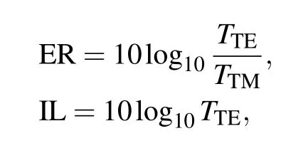
whereTTEandTTMare the transmittance of the TE and TM modes at the drop port for an input TE mode. In the above equations, if the through port is used as the output port, the similar expressions of ER and IL are figured out for an input TM mode.
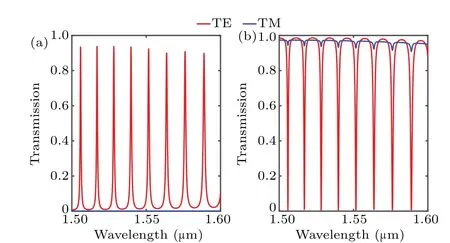
Fig. 4. Transmission spectra of TE (red lines) and TM (blue lines)modes at(a)drop port and(b)through port.
Figure 4(a) illustrates the transmission properties of TE and TM modes at the drop port of the microring resonator withW=WR=500 nm. As expected, the TE mode shows strong resonance at wavelengths of 1528.2 nm, 1539.79 nm,1551.64 and 1563.79 nm. The TM mode almost outputs from the through port,and at resonance wavelength very weak light goes through the drop port. Hence, the input TE and TM modes can be efficiently separated at the resonance wavelength with an ER as high as 33.21/24.97 dB and IL as low as 0.346/0.324 dB for the TE/TM mode at 1551.64 nm. The field evolution along the propagation distance of the designed P-DEMUX for TE mode and TM mode input is illustrated in Fig. 5. For TE mode, its field shows a significant resonant phenomenon in the microring resonator and is output from the drop port. While for the TM mode, the field directly goes through the through port.
The fabrication error tolerance of the proposed PDEMUX is also simulated by 3D-FDTD. By using thin-film deposition or thermal oxidation, the thickness of the slot and the strip thickness of the horizontal waveguide is well defined and under better control.[21]The main fabrication error comes from the photolithography and etching process. The error of the waveguide width is the dominant factor that influences the performance of the device. Here we define Δwgand Δwras waveguide width and microring width deviation,respectively.When the waveguide width has an increase of Δwgor Δwr,the gap between these waveguides will decrease a value of Δwgor Δwr. The range of Δwgand Δwris from-20 nm to+20 nm.The simulation results are shown in Fig.6.

Fig.5. Light propagation along the proposed P-DEMUX for the(a)TE mode and(b)TM mode.
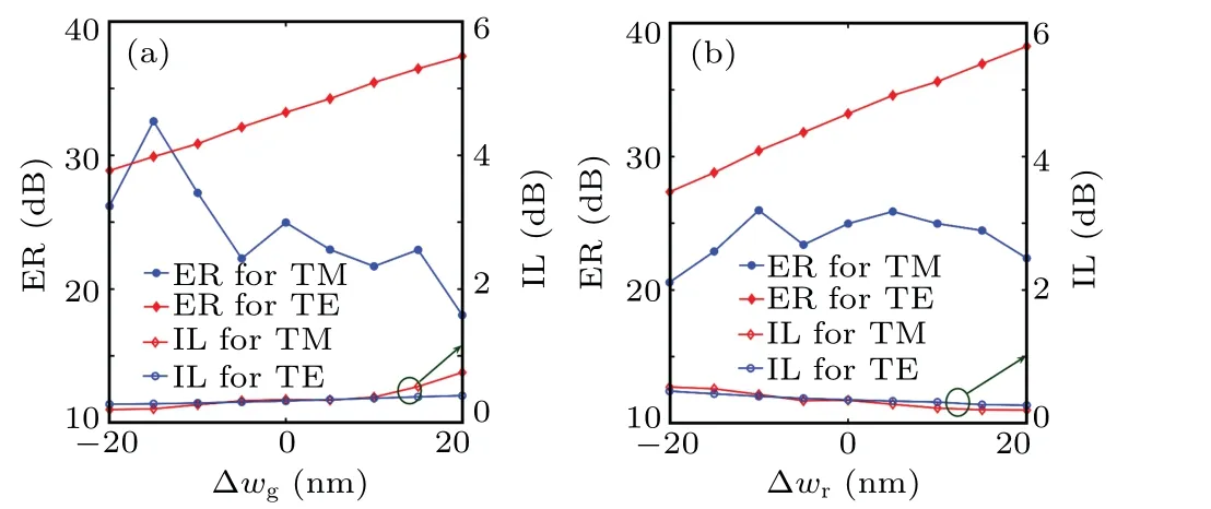
Fig.6. The ER and IL of the proposed P-DEMUX for the TE port and TM port with (a) the waveguide width and (b) the micro-ring width variation from-20 nm to+20 nm.

Table 1. Performance comparison between the reported and present P-DEMUXs based on microring resonators.
The ILs of both modes are insensitive to the fabrication error and the maximum value is 0.75 dB when the waveguide width deviates from the designed value by 20 nm. The ERs of the TE and TM modes show different behaviors. The ER of the TE mode changes approximately linearly with the increase of width. Since the coupling between the slot waveguide and ultrathin microring becomes strong gradually, the TE mode will almost output from the drop port at the resonance wavelength, which leads to the increase of the ER. For the ER of the TE mode is above 27 dB with the considered fabrication error, the ER of TM mode is the key to decide whether this device is fabrication friendly or not. For the width deviation from-20 nm to+15 nm,the ER of the TM mode will maintain above 20 dB,which shows that such a fabrication error is quite large for the complementary metal oxide semiconductor(CMOS)fabrication. The performance comparison for previously reported P-DEMUX based on micro-ring resonators is listed in Table 1. In this paper, the polarization-selective microring resonators is used, which can neglect the coupling of unexpected polarization light (TM mode) into the ring. The simulated ERs for TE and TM light are better than the reported results.In particular,compared with the traditional rings without polarization-selective function,the width fabrication tolerance of slot waveguide and microring shows great advantages.The comparison results verify the effectiveness of our device in increasing tolerance and ER.
3. Conclusion
In conclusion, using polarization-selective micro-ring resonators, we proposed P-DEMUX based on the silicon nitride-silica-silicon horizontal slot waveguide. The proposed device shows a high ER for both TE(33.21 dB)and TM modes(24.97 dB).At the resonance wavelength of 1551.64 nm,an IL of 0.346 dB and 0.324 dB for the TE and TM mode is obtained.It is worth noting that the microring resonators based on ultrathin waveguide is polarization-selective to work with resonances for TE polarization only. This proposed polarizationselective device shows a good tolerance to fabrication.
Acknowledgments
Project is supported by the National Natural Science Foundation of China (Grant No. 61804148) and the National Key Research and Development Program of China (Grant No.2018YFB2200202).
杂志排行

Chinese Physics B的其它文章
- Measurements of the 107Ag neutron capture cross sections with pulse height weighting technique at the CSNS Back-n facility
- Measuring Loschmidt echo via Floquet engineering in superconducting circuits
- Electronic structure and spin-orbit coupling in ternary transition metal chalcogenides Cu2TlX2(X =Se,Te)
- Characterization of the N-polar GaN film grown on C-plane sapphire and misoriented C-plane sapphire substrates by MOCVD
- Review on typical applications and computational optimizations based on semiclassical methods in strong-field physics
- Quantum partial least squares regression algorithm for multiple correlation problem