基于BDS和IMU的挖掘机铲斗位姿测量方法与试验
2022-03-10彭靖怡赖桑愉冯达文陈高隆王晨阳罗锡文
胡 炼,彭靖怡,赖桑愉,冯达文,陈高隆,王晨阳,罗锡文
基于BDS和IMU的挖掘机铲斗位姿测量方法与试验
胡 炼1,2,彭靖怡1,2,赖桑愉1,冯达文1,2,陈高隆1,2,王晨阳1,2,罗锡文1,2※
(1. 华南农业大学南方农业机械与装备关键技术教育部重点实验室,广州 510642;2.岭南现代农业科学与技术广东省实验室,广州 510642)
为提高农田建设中挖掘机施工作业精度和智能化程度,该研究提出了一种基于北斗卫星导航系统(BeiDou Navigation Satellite System, BDS)和惯性测量单元(Inertial Measurement Unit, IMU)的挖掘机铲斗位姿测量方法。首先,采用IMU测量挖掘机各执行机构的姿态角信息,解算获得挖掘机车体坐标系下铲斗末端的三维坐标,利用双天线BDS和IMU检测车体的位置和姿态建立了挖掘机铲斗末端三维坐标的实时解算模型,并设计了融合双天线BDS和IMU输出高频率高精度位姿的卡尔曼滤波算法。模拟挖掘机实际施工场景进行了静态和动态试验,采用全站仪验证铲斗末端三维坐标解算值。试验结果表明,该方法能准确实时测量挖掘机铲斗末端三维坐标,挖掘机铲斗末端三维坐标解算值与全站仪实测值的运动轨迹变化一致,同一时刻空间两坐标点距离均方根偏差小于30 mm,三个轴向坐标动态测量均方根偏差均在20 mm内,绝对偏差≤30 mm的数据占比不低于95.35%,挖掘机铲斗位姿的准确测量为挖掘机精准施工智能引导提供了基础。
农业机械;挖掘机;BDS;IMU;坐标转换;位姿测量
0 引 言
挖掘机是常用的工程机械,也是农业生产和农田建设广泛应用的机械,用于河渠水下淤泥清理、农田沟渠修建和农田改造平整等[1],为高标准农田建设发挥了重要作用。目前挖掘机的施工作业全凭操作人员的经验,在高精度造型、平整,以及视野受限的水下作业和地底挖掘等施工场景对于操作人员的要求很高,依靠操作人员经验难以保证工作质量和效率[2-4]。
近年来,人们对挖掘机的施工作业精度与作业效率的要求也越来越高,挖掘机智能化和自动化已成为重要发展方向,如精确感知挖掘机本身及其作业部件位姿信息实现轨迹控制和远程控制等[5-6]。为准确获取挖掘机作业部件位姿参数,目前基于传感器技术估计位姿是主要研究热点[7],如采用旋转编码器和电位计[8]、旋转电位计和倾角传感器[9]获取挖掘机的姿态信息。牛大伟[10]采用微机电系统传感器对挖掘机姿态信息进行测量,提高了姿态检测系统的工作稳定性与可靠性。日本小松挖掘机通过装载位移行程油缸获取油缸行程转换得到各机构臂的空间姿态角[5]、李海虹等[11]提出以液压缸行程的线位移测量取代关节转角测量,但位移行程油缸和转角传感器安装较困难,且接触式的转角传感器因机械磨损降低精度。在基于视觉技术中,为避免了传统位移传感器在恶劣工况与环境下的碰撞损坏与测量精度低的问题,倪佳敏等[12]通过神经网络建立油缸位移长度与标识点坐标间映射关系的工作装置虚拟位移传感器系统,但其只针对油缸位移传感器实现了非接触测量,功能较为单一;Xu等[13]提出一种利用基于视觉的神经网络系统估计液压机械手姿态,在测试平台进行了使用经过训练的神经网络估计器来估计机械手液压缸位移的仿真测试。Mulligan等[14]开发了一种基于边缘检测的倒角匹配方法来估计挖掘机操纵器的姿态,但是其图像处理方法的性能严重依赖于输入图像的质量;Liang等[7]采用深度卷积神经网络训练挖掘机图片集,基于堆叠沙漏网络算法估计机器二维姿态信息,再对三维位姿进行预测和重构,但其三维姿态是以二维姿态估计结果作为输入易产生累积误差,且该网络只能识别一台机器的位姿,不适用多机器共同作业场景;王海波等[15]基于视觉技术测量挖掘机工作姿态、朱建新等[16]提出了一种基于点云聚类特征值方图的目标识别方法,但在复杂的施工背景下提取图像特征以及提高算法的鲁棒性和准确性有待进一步研究。
位姿由位置和姿态两部分组成。在三维坐标系中,可以用质点的坐标表示位置,质点坐标与坐标原点组成的三维向量表示姿态,位置的变化即质点的平移过程,姿态的变化是向量的旋转过程。其中姿态的测量可通过多种方法实现,周云成等[17]提出一种基于时序一致性约束的自监督位姿变换估计模型以实现温室环境下机器人行进过程中的位置及姿态跟踪。李晨阳等[18]利用高频率里程计信息估计机器人位姿,但在农田等地面不平整的环境中,里程计信息存在一定误差。在基于传感器的方法中,使用了如惯性测量单元(Inertial Measurement Unit, IMU)、光学姿态测量系统、GPS姿态测量系统、无线局域网(WLAN)、射频识别(RFID)和基于超宽带(UWB)等方法[19-21]。在基于WLAN、RFID和UWB的三维姿态估计中,信号源被放置在固定位置,这在动态工作现场条件下并不适用[22]。IMU不受气候条件、空间条件限制,方便携带,成本因精度而定,适用于对测量精度、动态性能、实时性均有较高要求的领域,然而连续测量角度变化会受到磁干扰和漂移问题的影响。在基于GPS的姿态估计方法中,GPS估计的每个位置和航向相互独立,这解决了漂移问题,但其无姿态信息、数据率低且易受环境因素干扰[23-26]。随着中国北斗卫星导航系统(BeiDou Navigation Satellite System,BDS)建成,其已经在测量航向和姿态方面得到了广泛应用,为运动目标提供三维姿态信息,可以达到毫米级的静态定位精度和厘米级的动态测量精度[27-28]。
为此,本文提出基于BDS和IMU的挖掘机铲斗位姿测量方法,采用卡尔曼滤波算法获取车体准确位姿信息,建立铲斗三维坐标解算模型,解算挖掘机铲斗末端三维坐标。拟解决上述由于传感器特性及安装造成的精度、测量范围和抗振能力较差的问题,引导挖掘机精准完成平整、造型施工和水下施工等作业,减少人力成本和劳动强度,在达到精确作业的同时提高智能化程度。
1 基于BDS和IMU的铲斗位姿测量方法
1.1 坐标系转换
为了说明质点的位置、运动的快慢和方向等,必须选择相应的坐标系[28]。中国北斗卫星导航系统定位坐标采用的是大地坐标系,在工程上常用“高斯投影”方法将大地坐标系中的点(,,)转换成地理坐标系(x,y,z)(本文选择“东北天”为地理坐标系,简称G系,定义为:轴指向东,轴指向北,轴垂直于当地水平面,沿当地垂线向上),再平移至施工本地坐标系(简称t系)。为使铲斗末端姿态解算结果可直接用于施工,设施工本地坐标系的原点为,在G系的坐标为(x,y,z)[29],将地理坐标系的坐标(x,y,z)转换为施工本地坐标系下的坐标(x,y,z)可通过式(1)获得。
1.2 铲斗位姿测量原理
基于BDS和IMU的挖掘机铲斗位姿测量系统主要由BDS基站、BDS双天线、IMU姿态传感器、车载终端构成,如图1所示,在车顶上搭载BDS双天线以获取车体位姿信息(航向角与空间位置信息),并保证双天线间连线与驾驶室和各机械臂方向保持垂直;在车体上安装IMU姿态传感器读取车体横滚角与俯仰角;在挖掘机的动臂、斗杆、铲斗合适处安装IMU姿态传感器获取各机构姿态角变化;在驾驶室内安装车载终端连接BDS双天线和IMU,实时读取信息并解算出铲斗末端三维坐标,车载终端显示的铲斗末端三维坐标信息为操作人员提供准确的施工作业引导。
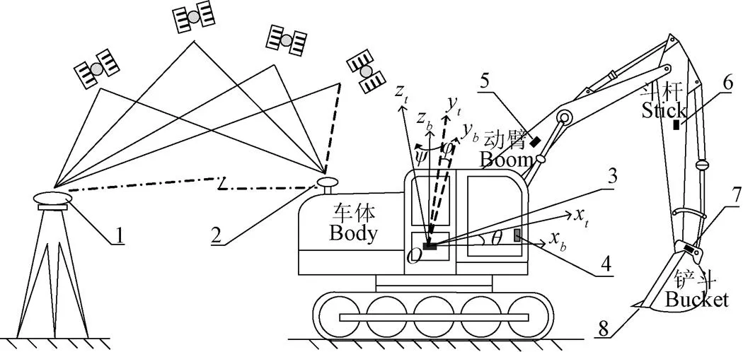
1.BDS基站 2.BDS双天线 3.车身IMU 4.车载终端 5.动臂IMU 6.斗杆IMU 7.铲斗IMU 8.铲斗末端
1.BDS (BeiDou Navigation Satellite System) base station 2.BDS dual antenna 3.IMU (Inertial Measurement Unit) on the body 4.Vehicular terminal 5.IMU on the boom 6.IMU on the stick 7.IMU on the bucket 8.End of excavator bucket
注:坐标系xyz为车体坐标系,以车体前进方向为x轴,y轴与x轴垂直指向车体方向的左侧,z轴垂直于xy平面向上;坐标系xyz为施工本地坐标系,x轴指向东,y轴指向北,z轴垂直于当地水平面,沿当地垂线向上;,,分别为车体偏航角、横滚角和俯仰角,(°)。
Note:xyzis the vehicle body coordinate system,xrepresents the forward direction of the car body,yperpendicular toxand point to the left side of the vehicle body,zaxis perpendicular toxyplane and upward;xyzis the local construction coordinate system,xpoints east,ypoints north,zis perpendicular to the local horizontal plane and upward along the local vertical line;,,are yaw, roll and pitch angles of the body respectively, (°).
图1 挖掘机铲斗位姿测量系统
Fig.1 The position and posture measurement system of excavator bucket
1.3 铲斗位姿测量算法
基于BDS和IMU的挖掘机铲斗位姿测量算法主要是建立挖掘机铲斗末端的坐标解算模型,包括以下几个步骤:1)利用双天线BDS和IMU卡尔曼滤波融合算法输出车体的位置和姿态,计算姿态旋转矩阵;2)根据几何关系或机器人运动学和所测量的各执行机构姿态角信息,解算基于车体坐标系的挖掘机铲斗末端的位置信息;3)测量计算挖掘机车身参数及BDS天线到质心位置的坐标增量,计算BDS天线至铲斗末端的坐标增量,解算基于施工本地坐标系下铲斗末端的三维坐标。基于挖掘机建立坐标系,坐标系及测量单元安装位置如图1所示,通过获取BDS双天线的位置和航向角信息以及车体、动臂、斗杆及铲斗的姿态信息,基于所获取信息和执行机构几何关系建立求解铲斗末端的三维坐标解算模型,并计算获得施工本地坐标系下铲斗末端的三维坐标。坐标解算模型如式(2)。

式中为施工本地坐标系下铲斗末端的三维坐标;为BDS天线的位置信息;1,2,3为各执行机构上IMU姿态传感器角度测量值。
位姿解算步骤如下:
1)BDS和IMU的卡尔曼滤波融合算法,计算车体姿态旋转矩阵
由于GNSS输出频率较低且易受干扰、IMU在动态测量过程中受频繁振动影响测量精度。因此,设计了卡尔曼滤波融合算法,融合BDS(频率10 Hz)输出定位信息和IMU(频率50 Hz)输出三轴加速度、角速度信息来估计最优车体定位信息和航向信息,保证位姿测量的实时性和准确性,以满足挖掘机实际应用的要求。
系统模型建立:


通过卡尔曼滤波融合具体输出过程如下:


(3)计算时刻的滤波增益;

式中为测量噪声协方差矩阵;

式中为测量向量。
(5)更新时刻误差估计的协方差

重复计算过程,直到算法结束,得到最优估计的车体定位信息和航向信息。
车体坐标系通过绕欧拉角横滚、俯仰、偏航3次旋转到与施工本地坐标系对齐。则()、()、() 3个旋转矩阵分别为


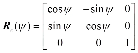
得车体坐标系转为施工本地坐标系的旋转矩阵:

2)计算基于车体坐标系下铲斗末端三维坐标0
挖掘机的动臂、斗杆及铲斗在同一平面内,其几何结构如图2所示,建立车体坐标系xoz和施工本地坐标系xoz,根据几何关系推算基于车体坐标系下铲斗末端三维坐标0。
求得车体坐标系下0的坐标为

注:坐标系xoz为施工本地坐标系;坐标系xoz为车体坐标系;()表示车体与动臂之间的关节,是施工本地(车体)坐标系的原点;1点表示动臂与斗杆之间的关节;2点表示斗杆与铲斗之间的关节;3点表示铲斗末端测量点;1表示动臂的长度,为()到点1的直线距离,m;2表示斗杆的长度,为点1到点2的直线距离,m;3表示铲斗的长度,为点2到点3的直线距离,m;1、2、3分别为动臂IMU、斗杆IMU和铲斗IMU测量值,(°);为车体在运动状态下车体坐标系基于施工本地坐标系的俯仰角,(°)。
Note: xozis the local construction coordinate system;xozis the car body coordinate system;() represents the joint between the body and the boom and is the origin of the local construction (body) coordinate system;1represents the joint between the boom and the stick;2represents the joint between the stick and the bucket;3represents the measuring points at the end of the bucket;1is the length of the boom, represents the linear distance from point() to Point1, m;2is the length of the stick, represents the linear distance from point1to Point2, m;3is the length of the bucket,represents the linear distance from point2to point3, m;1,2,3are the measured values of boom IMU, stick IMU and bucket IMU respectively, (°);is the pitch angle of the car body coordinate system based on the local construction coordinate system when the car body is in motion, (°).
图2 挖掘机几何结构图
Fig.2 Geometric structure diagram of excavator
3)计算基于施工本地坐标系下铲斗末端三维坐标
测量车体坐标系下BDS天线至车体坐标系原点的坐标增量0,可得基于车体坐标系下BDS天线至作业部件末端的坐标增量:
=0+0(15)
经过欧拉角旋转变换至施工本地坐标系下,可得:


2 挖掘机模型平台试验
2.1 试验材料
1)挖掘机模型试验平台
设计由铲斗、斗杆、动臂和回转平台组成的挖掘机模型平台,可模拟挖掘机各机械臂和回转关节运动,并在挖掘机模型平台上安装BDS双天线,如图3所示。试验选择施工本地坐标系的、、3个轴向来观察挖掘机铲斗末端真实值与解算值的误差,采用直线导轨滑块机构保证动态试验的3个坐标轴向运动直线度,导轨安装有位移传感器测量轴向运动位移[30],位移传感器采用WXY15M型,最大量程为400 mm,输入0~5 V电压,输出为模拟量,分辨率0.01,线性精度为0.02%FS,设置拉线传感器的采样频率为10 Hz。

1.斗杆长 2.动臂长 3.回转平台 4.拉线传感器 5.铲斗长 6.铲斗末端 7.BDS双天线
1.The length of excavator stick 2.The length of excavator boom 3.Rotary platform 4.Cable sensor 5.The length of excavator bucket 6.The end of excavator bucket 7.BDS dual antenna
注:车体坐标系轴指向正东,轴指向正北,轴垂直于平面向上;导轨滑块平台纵向分别与车体、、轴平行。
Note:Theaxis of the vehicle body coordinate system points to the east, theaxis points to the north, theaxis perpendicular toplane and upward. Make the longitudinal direction of the slide rail platform parallel to the,andaxes of the vehicle body, respectively.
图3 挖掘机模型试验平台
Fig.3 Model test platform of excavator
2)其他材料
BDS双天线系统(司南导航K726定位板卡,静态差分精度为水平面2.5 mm、高程5 mm,输出频率为10 Hz,航向角测量精度为0.2°/。其中,为双天线基线长,m)、DTU(型号:CM510-71F)、HWT605传感器(角度精度:、轴静态0.05°,动态0.1°,输出频率为0.2~200 Hz可调)、5 V直流稳压电源、NI myRIO模块、PCAN-USB 模块、USB 转串口线、笔记本计算机、多串口卡、Labview 软件和Matlab 软件。
2.2 试验方案
静态试验以车体坐标系轴指向东西南北4个方向且挖掘机机械臂在不同姿态的情况下,每个方向各进行3组试验。用BDS设备测量并记录铲斗末端三维坐标,转换到施工本地坐标系下,与铲斗位姿测量算法解算值计算3个轴向偏差。
动态试验采用直线导轨滑块平台实现3个轴向动态变化模拟真实挖掘机运动时铲斗末端三维坐标的变化,如图4所示。采用BDS设备以10 Hz的采样频率测量并记录导轨滑块平台的起始点的定位信息后,由导轨平台本身的几何特性及位移传感器的测量值推算此时铲斗末端三维坐标的真实值。试验选择施工本地坐标系下的、、3个轴向来观察铲斗末端真实值与算法解算值的偏差。

图4 挖掘机模型平台动态试验
2.3 试验结果与分析
2.3.1 静态试验
统计各组试验偏差:由铲斗位姿测量算法获取解算值,计算算法解算值与铲斗末端真实值两坐标点间的距离偏差和、、3个轴向偏差,结果如表1所示。

表1 铲斗末端三维坐标的静态试验结果
通过试验数据可知,在各种姿态下,测得、、3个轴向的最大绝对偏差分别为15.15、15.48和23.57 mm,均小于30 mm。解算值与真实值(验证值)两坐标点间的距离最小偏差为11.94 mm、最大偏差为29.03 mm、平均偏差为19.55 mm。
2.3.2 动态试验
统计6组试验偏差,根据挖掘机正常工作经验速度和试验模型尺寸综合考虑,试验挖掘机铲斗末端分别沿、、3个轴向以0.1和0.2 m/s水平运动进行2组试验,试验数据统计结果如表2所示。

表2 挖掘机模型平台铲斗末端三维坐标动态试验结果
由于每组试验认为只有当前坐标轴变化,所以试验结果中的偏差均为解算点与真实点之间的偏差。通过、、3个轴向的两组试验数据可知,解算值与真实值(验证值)之间的平均绝对偏差分别为8.81、14.87和16.37 mm,均方根偏差分别为10.74、18.15和18.85 mm,均小于20 mm;轴和轴的最大绝对偏差分别达到42.33和47.45 mm,这是因为挖掘机模型关节间运动时存在间隙,从而产生更大的偏差。
3 挖掘机现场试验
3.1 试验材料
试验采用山河swe40UF智能挖掘机、BDS双天线系统、HWT605姿态传感器、Android车载终端。试验中,采用徕卡MS60高速影像全站扫描仪(测量精度:1 mm,追踪运动轨迹输出频率为10 Hz)动态测量铲斗末端三维坐标。
3.2 试验方案
如图5所示,将基于BDS和IMU的挖掘机铲斗位姿测量系统安装在挖掘机上,在挖掘机车顶上安装双天线北斗卫星系统(BDS)以10 Hz的采样频率获取定位和航向角信息,并保证双天线间连线与驾驶室和各臂方向保持垂直;在车体上安装HWT605姿态传感器以50 Hz的采样频率读取车体横滚角与俯仰角;在挖掘机的动臂、斗杆、铲斗合适处安装HWT605姿态传感器获取各机械臂姿态角信息;在驾驶室内安装Android车载终端并连接BDS双天线和姿态传感器,以铲斗棱镜放置处为测量点,读取实时信息解算铲斗末端三维坐标。依据《建筑地基基础工程施工质量验收规范》(GB50202-2018)的场地平整土方开挖≤50 mm、填土≤30 mm和《高标准基本农田建设标准》(TD/T 1033-2012)田面高差应小于±30 mm的要求统计试验结果绝对偏差≤30 mm的数据占比。试验分为静态试验和动态试验。

图5 挖掘机动作试验现场图
静态试验时,挖掘机车体和机械臂在不同航向角和姿态为一组试验,采用全站仪连续采集每组试验动作下挖掘机铲斗处棱镜的三维坐标,计算与铲斗位姿测量算法实时解算值之间的偏差。
动态试验针对挖掘机施工作业中深挖、整平、刷坡等作业场景,操作挖掘机分别以试验组1:车身航向不动,各机构臂动作;试验组2:车身航向转动,各机构臂不动;试验组3:车身航向和各机构臂同时动作,3种试验动作来模拟实际施工场景。采用全站仪以10 Hz的采样频率自动追踪放置于铲斗的棱镜实时采集铲斗的三维坐标来验证与解算值之间的偏差。
3.3 试验结果与分析
3.3.1 静态试验
静态试验统计10组试验数据,求取每组试验数据平均值,数据统计结果如表3所示。

表3 挖掘机铲斗末端三维坐标静态试验结果
由表3可知,在不同姿态动作下,测量点、、3个轴向最大绝对偏差分别为17.69、14.99和11.68 mm,均小于20 mm;解算值与真实值(验证值)两坐标点间的距离最小偏差为7.40 mm、最大偏差为20.65 mm、平均偏差为13.57 mm。
3.3.2 动态试验
以动态试验方案模拟挖掘机进行3组作业场景试验,试验数据统计结果如表4所示。
从表4中3组试验数据可以看出,在不同的试验动作下,、、3个轴向坐标的解算值与真实值(验证值)之间的平均绝对偏差和均方根偏差均小于20 mm,且绝对偏差≤30 mm的数据占比均不低于95.35%。同一时刻,解算值与真实值(验证值)两坐标点间的距离均方根偏差分别为27.49、26.30和23.50 mm,均小于30 mm。
如图6所示,为挖掘机铲斗测量点在动态试验组1动作过程中,由铲斗测量点的三维坐标解算值和真实值(验证值)拟合成的三维空运动间轨迹图,挖掘机铲斗末端三维坐标解算值与全站仪实测值的运动轨迹变化一致。

表4 挖掘机铲斗末端三维坐标动态试验结果

图6 铲斗末端测量点空间轨迹图
试验结果表明基于BDS和IMU的挖掘机铲斗位姿测量方法能准确测量铲斗位姿,、、3个轴向均方根误差均小于20 mm,解算值与真实值两坐标点间的距离均方根误差均小于30 mm,在实现智能化、自动化作业的同时满足机械挖土施工要求和高标准农田建设标准要求。
4 结 论
1)提出了一种基于BDS和IMU的挖掘机铲斗位姿测量方法,利用双天线BDS和IMU传感器测量车体的位姿,采用IMU测量挖掘机各执行机构的姿态角信息,设计了挖掘机铲斗位姿测量系统。
2)设计了一种基于BDS和IMU的挖掘机铲斗位姿解算算法,并基于双天线BDS和IMU的卡尔曼滤波融合算法获取车体的位置和姿态,建立姿态旋转矩阵解算得到基于施工本地坐标系下铲斗末端的三维坐标。
3)以山河swe40UF智能挖掘机进行试验,将解算值与全站仪实测值比较,结果表明挖掘机铲斗末端三维坐标解算值与全站仪实测值的运动轨迹变化一致,同一时刻空间两坐标点距离均方根偏差小于30 mm,3个轴向坐标的动态测量均方根偏差均在20 mm内,绝对偏差≤30 mm的数据占比不低于95.35%,该方法可为挖掘机铲斗三维坐标实时解算和精准施工提供精确测量和智能引导,满足工程机械挖填土施工质量验收中国国家标准要求和高标准基本农田建设标准要求。
[1] 葛磊,董致新,李运华,等. 系列化液压挖掘机数字样机研究[J]. 机械工程学报,2019,55(14):186-196.
Ge Lei, Dong Zhixin, Li Yunhua, et al. Research on digital prototypes of serial hydraulic excavators[J]. Journal of Mechanical Engineering, 2019, 55(14): 186-196. (in Chinese with English abstract)
[2] Lee S U, Chang P H. Control of a heavy-duty robotic excavator using time delay control with integral sliding surface[J]. Control Engineering Practice, 2002, 10(7): 697-711.
[3] Papadopoulos E, Mu B, Frenette R. On modeling, identification, and control of a heavy-duty electrohydraulic harvester manipulator[J]. IEEE/ASME Transactions on Mechatronics, 2003, 8(2): 178-187.
[4] Yusof A A, Saadun M, Khairi M M, et al. Position control mathematical modelling and operational evaluation of tele-operated electro-hydraulic actuator (T-EHA)[J]. Applied Mechanics and Materials, 2015, 4014(773-774).
[5] 李傲傲. 挖掘机姿态检测系统研究[D]. 泉州:华侨大学,2019.
Li Ao'ao. The Research on Attitude Detection System of Excavator[D]. Quanzhou: Huaqiao University, 2019. (in Chinese with English abstract)
[6] 李运华,范茹军,杨丽曼,等. 智能化挖掘机的研究现状与发展趋势[J]. 机械工程学报,2020,56(13):165-178.
Li Yunhua, Fan Rujun, Yang Liman, et al. Research Status and Development Trend of Intelligent Excavators [J]. Journal of Mechanical Engineering, 2020, 56(13): 165-178. (in Chinese with English abstract)
[7] Liang C J, Lundeen K M, Mcgee W, et al. A vision-based marker-less pose estimation system for articulated construction robots[J]. Automation in Construction, 2019, 104: 80-94.
[8] Yamamoto H, Moteki M, Ootuki T, et al. Development of the autonomous hydraulic excavator prototype using 3-D information for motion planning and control[J]. Transactions of the Society of Instrument and Control Engineers, 2012, 48(8): 488-497.
[9] Gu J, Ma X D, Ni J F. Linear and nonlinear control of a robotic excavator[J]. Journal of Central South University, 2012, 19(7): 1823-1831.
[10] 牛大伟. 基于MEMS传感器的挖掘机姿态检测系统的研究[D]. 泉州:华侨大学, 2015.
Niu Dawei. The Research of the Excavator Attitude Detection System Based on MEMS Sensor[D]. Quanzhou: Huaqiao University, 2015. (in Chinese with English abstract)
[11] 李海虹,解晶琳,邹久礼,等. 液压传动机构位姿检测方法研究[J]. 实验技术与管理,2015,32(4):33-35.
Li Haihong, Xie Jinglin, Zou Jiuli, et al. Study on position and orientation measurement for a hydraulic transmission mechanism[J].Experimental Technology and Management, 2015, 32(4): 33-35. (in Chinese with English abstract)
[12] 倪佳敏,马伟,童欣,等. 基于视觉的挖掘机位姿测量虚拟传感器研究[J]. 电子测量技术,2022,45(9):44-49.
Ni Jiamin, Ma Wei, Tong Xin, et al. Vision-based virtual sensor research for excavator position measurement[J].Electronic Measurement Technology, 2022, 45(9): 44-49. (in Chinese with English abstract)
[13] Xu J Q, Yoon H S. Vision-based estimation of excavator manipulator pose for automated grading control[J]. Automation in Construction, 2019, 98: 122-131.
[14] Mulligan I J, Mackworth A K, Lawrence P D. A model-based vision system for manipulator position sensing[C]. Workshop on Interpretation of 3D Scenes, Austin, TX, USA, 1989.
[15] 王海波,邹海龙,张如照. 基于视觉测量的挖掘机工作装置姿态测量系统[J]. 农业机械学报,2015,46(4):302-308.
Wang Haibo, Zou Hailong, Zhang Ruzhao. Attitude measurement system for excavator’s manipulator based on vision measurement[J]. Transactions of the Chinese Society for Agricultural Machinery, 2015, 46(4): 302-308. (in Chinese with English abstract)
[16] 朱建新,沈东羽,吴钪. 基于激光点云的智能挖掘机目标识别[J]. 计算机工程,2017,43(1):297-302.
Zhu Jianxin, Shen Dongyu, Wu Kang. Target recognition for intelligent excavator based on laser point cloud[J]. Computer Engineering, 2017, 43(1): 297-302. (in Chinese with English abstract)
[17] 周云成,许童羽,邓寒冰,等. 基于自监督学习的温室移动机器人位姿跟踪[J]. 农业工程学报,2021,37(9):263-274.
Zhou Yuncheng, Xu Tongyu, Deng Hanbing, et al. Self-supervised pose estimation method for a mobile robot in greenhouse[J]. Transactions of the Chinese Society of Agricultural Engineering (Transactions of the CSAE), 2021, 37(9): 263-274. (in Chinese with English abstract)
[18] 李晨阳,彭程,张振乾,等. 融合里程计信息的农业机器人定位与地图构建方法[J]. 农业工程学报,2021,37(21):16-23.
Li Chenyang, Peng Cheng, Zhang Zhenqian, et al. Positioning and map construction for agricultural robots integrating odometer information[J]. Transactions of the Chinese Society of Agricultural Engineering (Transactions of the CSAE), 2021, 37(21): 16-23. (in Chinese with English abstract)
[19] 班朝,任国营,王斌锐, 等. 基于IMU的机器人姿态自适应EKF测量算法研究[J]. 仪器仪表学报,2020,41(2):33-39.
Ban Zhao, Ren Guoying, Wang Binrui, et al. Research on self-adaptive EKF algorithm for robot attitude measurement based on IMU[J]. Chinese Journal of Scientific Instrument, 2020, 41(2): 33-39. (in Chinese with English abstract)
[20] 赵自雨,冯仲科,田艺,等. UWB定位摄影测树仪设计与试验[J]. 农业工程学报,2020,36(17):167-173.
Zhao Ziyu, Feng Zhongke, Tian Yi, et al. Design and test of photographic dendrometer based on Ultra Wide Band (UWB) positioning[J]. Transactions of the Chinese Society of Agricultural Engineering (Transactions of the CSAE), 2020, 36(17): 167-173. (in Chinese with English abstract)
[21] 戴厚德,曾现萍,游鸿修,等. 基于光学运动跟踪系统的机器人末端位姿测量与误差补偿[J]. 机器人,2019,41(2):206-215.
Dai Houde, Zeng Xianping, You Hongxiu, et al. Pose measurement and error compensation of the robot end-effector based on an optical tracking system[J]. Robot, 2019, 41(2): 206-215. (in Chinese with English abstract)
[22] Mahmood B, Han S U, Seo J. Implementation experiments on convolutional neural network training using synthetic images for 3D pose estimation of an excavator on real images[J]. Automation in Construction, 2022, 133: 103996.
[23] 钟银,薛梦琦,袁洪良. 智能农机GNSS/INS组合导航系统设计[J]. 农业工程学报,2021,37(9):40-46.
Zhong Yin, Xue Mengqi, Yuan Hongliang. Design of the GNSS/INS integrated navigation system for intelligent agricultural machinery[J]. Transactions of the Chinese Society of Agricultural Engineering (Transactions of the CSAE), 2021, 37(9): 40-46.(in Chinese with English abstract)
[24] 赵福生,杨宏瑞,薛艳丽. GNSS与IMU集成原理及其改进分析[J]. 测绘通报,2016(6):60-63.
Zhao Fusheng, Yang Hongrui, Xue Yanli. GNSS and IMU integration principle and improvement analysis[J]. Bulletin of Surveying and Mapping, 2016(6): 60-63. (in Chinese with English abstract)
[25] Takai R, Yang L , Noguchi N. Development of crawler-type robot tractor based on GNSS and IMU[J]. IFAC Proceedings, 2013, 46(4): 95-98.
[26] 景云鹏,刘刚,金志坤. GNSS双天线结合AHRS测量农田地形[J]. 农业工程学报,2019,35(21):166-174.
Jing Yunpeng, Liu Gang, Jin Zhikun. Topographic survey of farmland based on GNSS dual antenna combined with AHRS[J]. Transactions of the Chinese Society of Agricultural Engineering (Transactions of the CSAE), 2019, 35(21): 166-174. (in Chinese with English abstract)
[27] 许江宁,朱涛,卞鸿巍. GPS姿态测量技术综述[J]. 海军工程大学学报,2003,15(3):17-23.
Xu Jiang, Zhu Tao, Bian Hongwei. Review on GPS attitude determination[J]. Journal of Naval University of Engineering, 2003, 15(3): 17-23. (in Chinese with English abstract)
[28] 陈云, 何艳. 基于GNSS姿态与电机编码器的农机转向角度测量系统研制[J]. 农业工程学报, 2021,37(10):10-17.
Chen Yun, He Yan. Development of agricultural machinery steering wheel angle measuring system based on GNSS attitude and motor encoder[J]. Transactions of the Chinese Society of Agricultural Engineering, 2021,37(10):10-17.(in Chinese with English abstract)
[29] He J, Luo X W, Zhang Z G, et al. Positioning correction method for rice transplanters based on the attitude of the implement[J]. Computers and Electronics in Agriculture, 2020, 176: 105598.
[30] Hu L, Yang W W, He J, et al. Roll angle estimation using low cost MEMS sensors for paddy field machine[J]. Computers and Electronics in Agriculture, 2019,158: 183-188.
Method and experiments of excavator bucket position and attitude measurement using BDS and IMU
Hu Lian1,2, Peng Jingyi1,2, Lai Sangyu1, Feng Dawen1,2, Chen Gaolong1,2, Wang Chenyang1,2, Luo Xiwen1,2※
(1.,,510642,; 2.,510642,)
High precision and intelligent degree of excavator construction can be perferred in farmland reconstruction in modern agriculture. It is a high demand to real-time acquire the bucket position and attitude for the intelligent and accurate operation of excavator. In this study, a series of approaches were proposed to measure the bucket position and attitude of excavator using BeiDou Navigation Satellite System (BDS) and Inertial Measurement Unit (IMU). A real-time solution model was established for the three-dimensional coordinates of the excavator bucket end: Firstly, the body parameters of excavator were measured to establish the body coordinate system. The IMU attitude sensors were installed at the appropriate positions of the boom, stick, and bucket of the excavator, in order to measure the attitude angle information of each actuator in the excavator. The data was finally collected to obtain the three-dimensional coordinates of the bucket end under the excavator body coordinate system; Then, the BDS dual antenna was installed on the roof to obtain the yawing angle of vehicle body and spatial position. The IMU attitude sensor was also installed on the vehicle body for the rolling angle and pitching angle of the vehicle body. Then, the Kalman filtering algorithm is used to fuse the dual antenna BDS and IMU output high-frequency and high-precision position and attitude information to construct attitude rotation matrix. Among them, the three-dimensional coordinates of the excavator bucket end under the vehicle body coordinate system were rotated to the local construction coordinate system. Static and dynamic tests were carried out to simulate the actual construction scene of the excavator. In the static test, the three-dimensional coordinates of the prism were continuously collected at the excavator bucket under each group of test actions by the total station under different heading angles and attitudes of the simulated operating excavator body and mechanical arm. The deviation was then calculated between the measured of total station and solution of bucket pose measurement. The results show that the new model performed better to accurately measure the three-dimensional coordinates at the end of the excavator bucket. The maximum absolute deviations were 17.69, 14.99, and 11.68 mm (all less than 20 mm) in the,, andaxial coordinates of bucket measuring points, respectively. The minimum deviation, maximum deviation and average deviation of the distance between the two coordinate points of the calculated and the real value (verification value) were 7.40, 20.65, and 13.57 mm, respectively. In the dynamic test, the excavator was operated in test group 1: where the body heading remained still, as each mechanism arm acted; Test group 2: the vehicle body rotated in the heading, and each mechanism arm remained still; Test group 3: The body heading and each mechanism arm acted at the same time, in order to simulate the actual construction operation scene, such as deep excavation, leveling, and slope brushing in the excavator construction. The total station was used to automatically follow the prism on the bucket. The three-dimensional coordinates of the bucket were collected in real time to verify the three-dimensional coordinate calculation of the bucket end. The results show that the average absolute deviation and root mean square deviation were less than 20 mm between the calculated values of the,,three axial coordinates and the real value under different test actions. The proportion of the data with the absolute deviation less than 30 mm were not less than 95.35%. The calculated three-dimensional coordinates at the end of the excavator bucket were better consistent with the movement track change of the measured total station. The root mean square deviations of the distance between the two coordinate points of the calculated and the real value were 27.49, 26.30, and 23.50 mm, respectively, which were less than 30 mm. The accurate measurement for the position and posture of the excavator bucket can provide a practical basis for the intelligent guidance of the precise construction of the excavator.
agricultural machinery; excavator; BDS; IMU; coordinate transformation; position and attitude measurement
10.11975/j.issn.1002-6819.2022.23.002
TU621; S222.5
A
1002-6819(2022)-23-0012-08
胡炼,彭靖怡,赖桑愉,等. 基于BDS和IMU的挖掘机铲斗位姿测量方法与试验[J]. 农业工程学报,2022,38(23):12-19.doi:10.11975/j.issn.1002-6819.2022.23.002 http://www.tcsae.org
Hu Lian, Peng Jingyi, Lai Sangyu, et al. Method and experiments of excavator bucket position and attitude measurement using BDS and IMU[J]. Transactions of the Chinese Society of Agricultural Engineering (Transactions of the CSAE), 2022, 38(23): 12-19. (in Chinese with English abstract) doi:10.11975/j.issn.1002-6819.2022.23.002 http://www.tcsae.org
2022-09-25
2022-11-22
岭南现代农业科学与技术广东省实验室科研项目(NT2021009);广东省科技计划项目(2021B1212040009);国家自然科学基金项目(32101623)
胡炼,博士,青年教授,研究方向为智能农机装备和无人农场。Email:lianhu@scau.edu.cn
罗锡文,教授,中国工程院院士,研究方向为智能农机装备研究。Email:xwluo@scau.edu.cn