Analysis of the line current differential protection considering inverter-interfaced generation station and countermeasures
2022-02-25MAKaiqiWANGYanboCHENZhe
MA Kaiqi, WANG Yanbo, CHEN Zhe
Department of Energy Technology, Aalborg University, Aalborg 9220, Denmark
[Abstract] Recently, the penetration of renewable energies in the transmission system has increased evidently, and this brings significant challenges for the existing protection systems.This paper focused on the line current differential protection in the power networks connecting to the inverter-interfaced generation station (ⅡGS).Combining the various fault control strategies popular in the inverter-interfaced generator (ⅡG), as well as the ⅡGS penetration level, the decoupled sequencecontrol (DSC) scheme was developed during asymmetrical grid faults.Compared with the conventional non-decoupled control scheme, DSC is effective to eliminate the influence of second harmonic oscillations in the active power output and the DC-link voltage, meanwhile, the DSC is capable of emulating the fault behavior of SG, improving the system voltage stability and protection adaptability.Simulation verification based on the DIgSILENT/PowerFactory was carried out.Simulation results show that the current differential protection is in risk of weak sensitivity (or even malfunction) during non-grounded interphase faults under certain ⅡG fault control modes, but the sensitivity of line current differential protection can be improved by using DSC scheme.
[Key words]inverter-interfaced generation station; line current differential protection; fault control; negative sequence control
1 Introduction
In recent years,huge progress in different fields of electric power industry for power electronic technology has been achieved. In term of the power generation,it is mainly the renewable energy (RE) generation[1]. In general,small-scale REs are integrated at the distribution utilities in distributed manners or organized as micro-grids. However,with the increase of PE penetration level,they are gradually integrated at distribution/transmission level in the way of power station (power plant)[2].
As a proven technique,line differential protection has been widely used to protect the transmission line[3]. To date,many reported works on the influence analysis of REs on the line differential protection focus on the DFIG-based networks[4,5]. Generally,crowbar protected DFIG provides a bypass for the fault current,leading to more different current features (i.e. frequency drift featured of attenuation) than the normal conditions when the fault occurs[6]. However,this mainly causes the transient delay for differential protection rather than malfunction[7]. ⅡG is one of the popular RE categories widely installed in the modern power system. Compared with the traditional synchronous generator (SG),ⅡG has totally different fault characteristics,e.g. smaller short-circuit capacity[8]and susceptible to control strategies[9],which brings adaptability issues for the traditional relaying methods[10,11]. In ref.[12],the influence of ⅡGS on the line current differential protection is investigated based on the angular features of the ⅡG fault current. However,the control diversity of ⅡG is not studied. As summarized in review work of[13],transmission operators (TSOs) from different countries have formulated various requirements for the ⅡGs with an evident penetration level. As a result,it is necessary for the good understanding of the protective issues related to the different ⅡG fault control strategies. Based on the multi-target selection of the ⅡG fault control modes,the malfunction mechanism of current differential protection is further analysed in this paper.
2 Control model and fault analysis
2.1 ⅡG fault control
The advanced control and technologies are being developed to integrate more REs into the modern power system. Because it can strongly affect the fault behavior and response of ⅡGs,the control strategy employed by ⅡGs should be considered in detail.
During grid faults,the ⅡG is deemed of operating in the grid-feeding mode with the outer functional power loop being bypass. At the moment,only the inner current control loop is activated and the reference commands of the current controller are generally generated from the so-called grid codes specified by TSOs.
As we know,the ⅡGS is able to provide available reactive current to support the recovery of system voltage when grid faults occur. For this purpose,many grid codes have given related reactive current supply requirements. Taking the requirements of Gemany grid codes as an example,the reactive current output from ⅡG has a high priority during abnormal system conditions. Then,the rest capacity can be occupied by active current produce. Figure 1(a) first illustrates the previous version of reactive current supply requirement during the grid faults,in which there is no technical rule for the negative sequence system. With the development of ⅡG grid connecting technologies,an improved reactive current supply rule covering the negative sequence reactive current regulation is presented,as given in Figure 1(b).
To meet the expected control of negative sequence system during asymmetrical grid faults,the decoupled sequence control (DSC) scheme is developed[14]. Compared with the conventional non-decoupled control scheme,DSC is effective to eliminate the influence of second harmonic oscillations in the active power output and the DC-link voltage. Meanwhile,the DSC is capable of emulating the fault behavior of SG,improving the system voltage stability and protection adaptability.
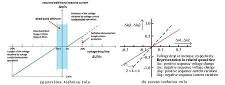
Fig.1 The reactive output current during voltage disturbances
Figure 2 depicts the DSC diagram of the grid side converter (GSC),which decouples the control loop in the rotation reference frame into two individual sequence sub-loops. In the control system,and are the instantaneous current and voltage measurements at the point of common coupling (PCC). Subscripts ‘d’ and ‘q’ represent the components in the rotating reference frame,while ‘+’ and ‘-’ denote the components in positive and negative sequence systems. Besides,superscript ‘"’ indicates the reference signal of the current commands. Generally,the negative sequence active current exchange from ⅡGs is not expected,the reference command is directly set as 0. The rotating angle S is adopted to compensate the angular difference of negative sequence system to the positive sequence voltage-based PLL outlet.
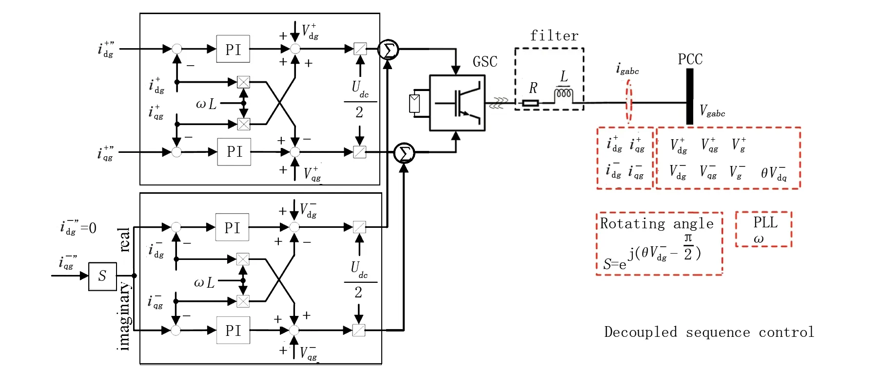
Fig.2 The decoupled sequence control (DSC) diagrams of the GSC
2.2 Fault feature study
As shown in Figure 3,a 400kV transmission network connecting ⅡGS is modeled in DIgSILENT/ PowerFactory to investigate the fault feature of ⅡG control and its influence on line current differential protection. System operates in 50 Hz,and the grounding mode is as shown in the figure. The aggregated ⅡGS with 240 MW rated power is connected to the main grid through the step-up transformer. SG represents the system slack node. Protective zone of the current differential protection is Line L2,3. Detailed parameters of the line and other system parameters are as given in the figure. Here,the DSC isadopted in the ⅡGS system.
Actually,the DSC can run in different fault control modes,i.e. balanced current control mode and DSC mode,according to the situation whether the negative sequence current control loop is enabled. In this section,the fault response of ⅡG-based plant is first evaluated.
Considering an interphase fault BC located at 40km away from terminal B2,Figure 4 displays the ⅡG current output under different control modes. From the Figure 4,it can be seen that ⅡG-based plant shows different current contributions in the condition of grid fault. In Figure 4(a),the ⅡG-based plant,operating in the balanced current control mode,can only outputs balanced fault currenteven if the unbalanced grid fault occurs. However,the ⅡG-based plant operating in the DSC mode can inject the negative sequence current during the unbalanced grid fault,as shown in Figure 4(b).In short,the fault feature of ⅡG is fully determined by its control strategies during grid faults.

Fig.3 The simulation model:The outgoing transmission system of ⅡG-based plant

Fig.4 The fault response of ⅡG-based plant for fault BC (Rf= 5Ω)
3 Influence of ⅡG control on the current differential protection
3.1 The demerit of the existing protection challenge analysis
Current differential protection is commonly applied for the protection of a specified zone or a piece of equipment. It is based on the Kirchhoff’s current law,and compares the input and output currents of the zone or the equipment. For an internal short-circuit fault in the zone or the equipment,the differential current (difference between input and output currents) will exceed a predefined threshold,activating the output of tripping signal.
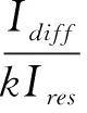
The percentage current differential protection is one of the popular relay type adopted in the transmission line. The protection criterion can be expressed as:
(1)
Where:IdiffandIresare the differential and restraining current variables,respectively.Iop[0]is the threshold current (pickup current).Iop[0]is the restraining coefficient,which is set as 0.8.
Ref.[12] has outlined the influence of ⅡGs on the differential protection (For detailed analysis,please refer to the reported work). According to the studies,it can be concluded as:
1)Not only the grid fault conditions but also the ⅡG fault control strategies;
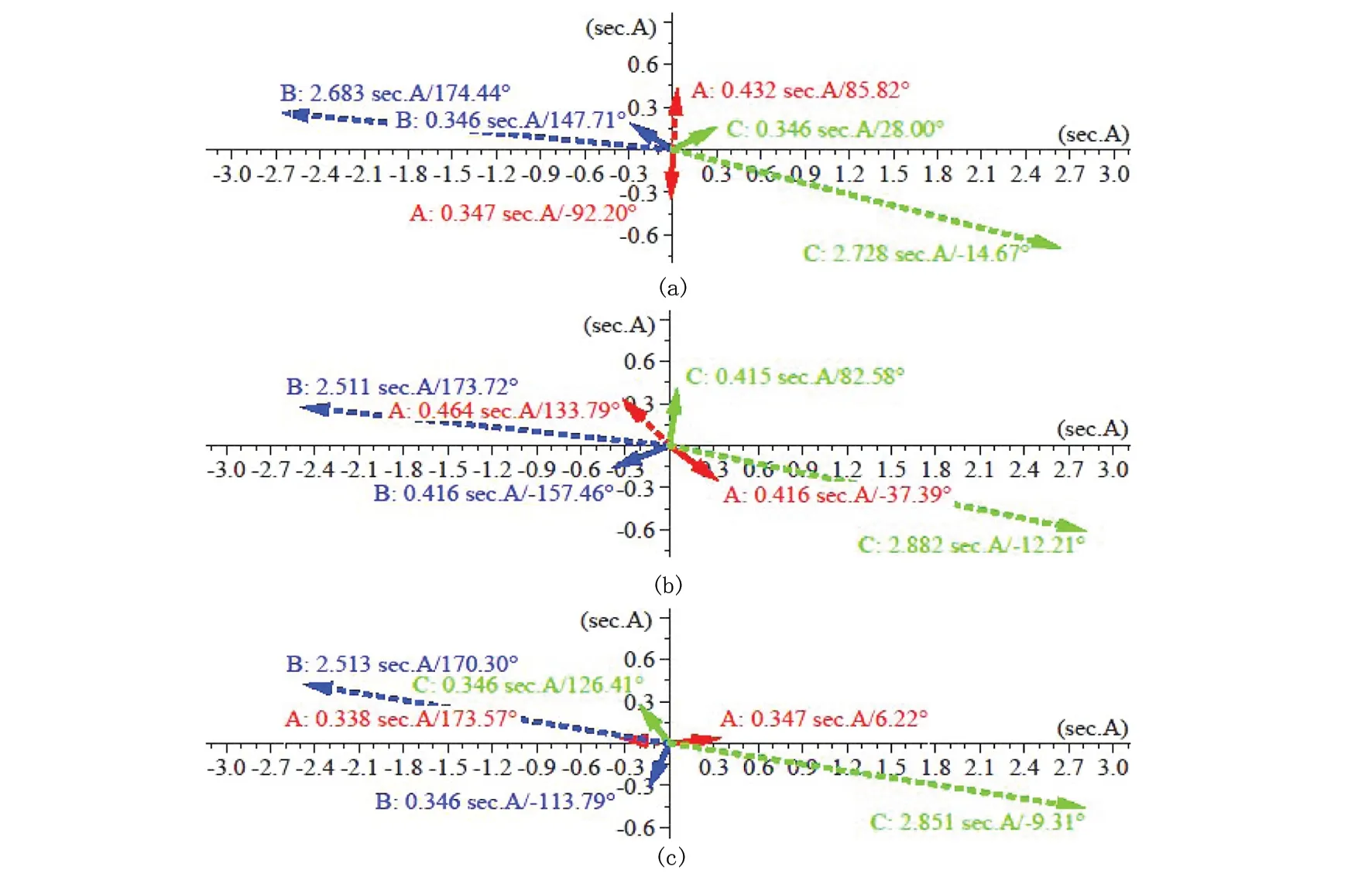
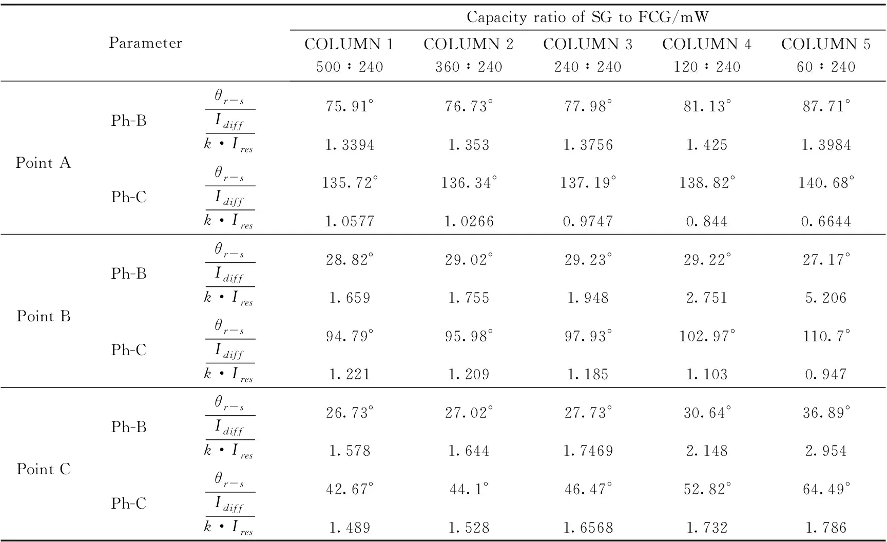
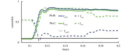
2)For interphase faults (non-grounded),one of the differential elements in the faulty phase would probably be in the risk of malfunction under certain fault conditions when the high penetration ⅡG operates in the balanced current control mode,Because the balanced phase angle feature at the ⅡG side can cause an over-angle-difference between the fault current at the ⅡG side and remote end(As the condition depicted in Figure 5,Idiff 3)For interphase faults (grounded),the evident zero-sequence current during ground faults can weaken the over-angle-difference to a safe degree,improving the sensitivity problem mentioned in 2),this is correct,however,a more detailed influence of the control strategies on the over-angle-difference problem is studied. As for the existing grid codes,according to the situation whether there is the reactive current supplyrequirement,it can be thought that the ⅡGs operates at either Point A or point B,as depicted in Figure 6. Fig.5 The vector diagram of the Fig.6 The vector diagram of the current commands of ⅡG over-angle-difference in dq reference frame (ⅡG operating points) 图5 相位差超过90°时的矢量图 图6 在dq参考坐标ⅡG状态下电流控制矢量图 (ⅡG运行点) Point A represents the condition of ⅡGs only output active power in the maximum capacity after grid faults. On the contrary,reactive current output is prior at Point B,and the rest capacity of ⅡGs is left for active current transfer. As a comparison,Point C is also selected in this paper,at which only output of the same amount of reactive current exists as Point B. In this section,the influence of different ⅡG operating points after grid faults on the angular features of ⅡG fault current and differential element are first tested under the balanced current control mode. By testing a fault BC at point F1 in the system of Figure 3,Figure 7 displays the complex plane representation of the steady-state fault current phasors at different ⅡG operating points. The capacity ratio of SG to ⅡG is set as 500:240 MW in this test case,which represents the situation of a small penetration ⅡGs. Fig.7 Complex plane representation of the steady-state fault current phasors at different ⅡG operating points (solid arrow: ⅡG side; dashed arrow: SG side) From Figure 7(a),it can be seen that the current phasors at ⅡG side is relatively symmetrical to the SG side when ⅡG operates at Point C. This approximately accords with the fact under the ideal condition with no active power transfer and ignoring the network loss. Compared with Figure 7(a),the current phasors of ⅡG rotates to a leading position when ⅡG operates at Point B,as shown in Figure 7(b). Furthermore,the leading angle rotation is around 90° when ⅡG operates at Point A (compared with the operating Point C). In addition,it can be seen that the angle difference in fault phase C increases from 42.67° to 94.79° then to 135.72° following the ⅡG moving from operating Point C to B then to A. It indicates the differential element faces an increasing malfunction risk. And,this malfunction risk is due to the increasing active power transfer from ⅡGs causes leading rotation of the current phasors at ⅡG side during grid faults. Being similar to Figure 7,it can be seen also that there exists the increasing malfunction risk in other columns with different capacity ratios in the table when ⅡG moves from operating Point C to B then to A. As the colored study cases in the table,the differential element has lost the sensitivity. Besides,it is clear that the malfunction risk increases with the increase of ⅡG penetration level (from column 1 to column 5,as shown in Table 1 for the same ⅡG operating points (e.g. Point A and B). Table 1 The angular difference of faulty phase currents and protection variable In this section,the effects of DSC scheme are mainly studied based on the ⅡG operating condition at Point B. Taking the study case in column 5 with evident penetration of ⅡG as an example,the dynamic differential and restraining currents are plotted in Figure 8. In this case,fault BC occurs at 0.1s and the negative sequence control loop is activated (i.e. the negative sequence reactive current injection) at 0.16s. Fig.8 The dynamic performance of the differential protection From Figure 8,it can be seen that the fault cannot be detected correctly by the differential element in phase C before 0.16s (referring to the criterion (1)). However,the sensitivity of the differential element is effectively improved after the activation of the negative sequence control loop at 0.16s. Except for the discoveries in ref.[12],from the study in Section 3,the influence of ⅡG control strategies on the current differential protection during non-grounded interphase faults also includes the following two aspects: 1)Different control modes of the ⅡGs (i.e. the different operating points) can heavily affect the performance of the current differential protection. 2)The negative sequence reactive current injection mentioned in the modern grid code can improve the sensitivity of differential element in a certain degree. Finally,as discussed in Section 3.2,differential protection shows best the sensitivity in the condition of ⅡGs operating at Point C,where no positive sequence active current is output from the ⅡGs. Thus,a suggestion for this over-angle-difference caused relaying issue is to give priority to the reactive current supply and decrease the active current output of the ⅡG in the positive sequence system at the same time. In this paper,based on the existing angular characteristics of the ⅡG fault current in ref.[12],the performance of the line current differential protection in a transmission network connecting ⅡGS is further evaluated. With the consideration of various technical rules for ⅡGs in different grid codes,this paper emphasizes on the influence analysis of the different ⅡG control strategies on the differential protection. From the targeted simulation verification,new discovery of the ⅡG control effects on the current differential protection is discussed and corresponding countermeasure is suggested finally.
3.2 Balanced current control
3.3 DSC condition
4 Discussion
5 Conclusion
