A study on nuclear analysis of the divertor region of the CFETR
2022-01-10RayyanSAIDAHMEDDamaoYAO姚达毛QiuranWU伍秋染SonglinLIU刘松林andTiejunXU许铁军
Rayyan SAIDAHMED, Damao YAO (姚达毛), Qiuran WU (伍秋染),Songlin LIU (刘松林) and Tiejun XU (许铁军)
1 Institute of Plasma Physics, Chinese Academy of Sciences, Hefei 230031, People’s Republic of China
2 University of Science and Technology of China, Hefei 230027, People’s Republic of China
Abstract This paper presents the nuclear analysis performance of the Chinese Fusion Engineering Test Reactor (CFETR) divertor region using the MCNP-5 Monte Carlo N-particles code in a 3D geometry model.We assessed the nuclear responses of the divertor region component systems and evaluated their shielding capability, which can support the development strategy of the physical and engineering design of the CFETR.Model specification based on the latest CAD model of the CFETR divertor has been integrated into the CFETR MCNP reference model with a major/minor radius R=7.2 m/a=2.2 m in the 22.5° model, and a fusion-power range of around 1–1.5 GW.The nuclear heating and radiation damage of the divertor system are enhanced compared to that of the ITER and the earlier CFETR design.The initial nuclear responses of the toroidal field coil and vacuum vessel systems showed that the shielding of the current divertor design is not sufficient and optimization work has been carried out.We also carried out calculations and analysis using a hypothetical operating scenario of over 14 years.An excellent improvement in the nuclear performance has been obtained by the improved additional shielding block in the divertor region when referring to the ITER design limit, which can support the design of the future update of the divertor region systems of the CFETR.
Keywords: CFETR, fusion reactor, divertor, nuclear analysis, divertor region
1.Introduction
Plenty of interest has been triggered in nuclear fusion compared with other alternative energy sources due to its carbonfree nature, absence of fissile materials with long-lived radioactivity,and abundance of deuterium and lithium resources on Earth.Over the years, much research has been conducted on magnetic fusion technology to develop and exploit this promising technology in the pursuit of clean energy.
Scientists have begun to construct fusion devices to acquire knowledge beyond this technology and achieve plasma from nuclear fusion more effortlessly.Among the generations of fusion reactors,the ITER project is making substantial progress toward the generation of fusion power.However, some further technologies and scientific issues relating to fusion need to be addressed, such as plasma stability, high-performance steadystate plasma for long life and high-performance equipment for fusion reactor generation [1].The Chinese Fusion Engineering Test Reactor (CFETR) is the next promising device to realize fusion energy, filling the gap between the experimental fusion reactor (ITER) and the demonstration reactor through high technology,high-limit fusion power,duty cycle time(or burning duration) (30%–50% longer) and self-sustained breeding conditions(DEMO)[2].The physics and engineering designs of the CFETR are still under development, starting from phase I,which includes a major/minor radius of 5.7 m/1.6 m and plasma current of 10 MA, towards phase II in pursuit of improving the design and performance by building a larger facility size ofR=6.6 m/a=1.8 m[3].The latest structure of the CFETR was initialized in 2018,with the most recent facility size further increased toR=7.2 m,and fusion power extended from 200 MW, 500 MW and 1 GW to 1.5 GW in just one facility,which will make it more adaptable but more challenging in terms of its engineering design [4].

Figure 1.One of 16 sectors of the CFETR (a) and the vertical cutting model (b).
The nuclear analysis attempts to track the design progress are regarded as a critical phase in the divertor region design to ensure optimal operation of the components, and could also provide more information about the divertor’s neutronic performance.The nuclear heating caused by neutrons and secondary photons to the plasma-facing units (PFUs) of the divertor and the cassette body (CB) are key locations that must be constantly cooled adequately.The damage induced by neutron irradiation could degrade the material characteristics of the system’s components.The overall divertor system is unable to offer enough protection to the vacuum vessel(VV) and toroidal field coil (TFC), especially with the latest design features of the CFETR due to the fact that several significant modifications have been adopted, which might cause changes in its neutronics performance [3, 4].
To prevent all of the negative effects on the divertor’s performance, the irradiation effects on the VV and TFC should be calculated [5].The results of the nuclear analysis for the divertor system and bottom area of the CFETR facility will be used to assist the modification and development of the facility’s physical and engineering design.A general Monte Carlo N-Particle transport code (MCNP-5) applied in a 3D neutronics model was adopted to describe the structure systems and was coupled with the FNDEL 2.1 nuclear library to evaluate the CFETR divertor region.
2.Structure model
2.1.Divertor region design
The divertor region is located at the bottom area of the CFETR and consists of a divertor assembly covered by the VV system through the TFC.The divertor is one of the most important systems in the CFETR, designed primarily to manage impurity particles and heat load from the plasma, as well as to protect the CFETR’s bottom region from damage caused by the plasma containing high-radiation particles.The CB is reusable to support the PFU, and is considered as the first confinement barrier of the plasma heat load for the VV and TFC systems, as shown in figure 1 [2, 6].The important functions of the VV design system are to successfully lower the plasma heating temperature and restrict radioactive damage to the materials forming the in-vessel components,as well as the blanket and divertor systems, to contribute to the plasma stability by preserving the electrical resistance of the toroidal control as much as possible and insulating the TFC system from radiation damage[7].The TFC nuclear response estimations compared with the primary design target can be used as an assessment of the capability of the divertor region design [4].
2.2.Modification and integration of 3D neutronics model components
The cosVMPT software [8, 9] was used to integrate the 3D neutronics divertor module into the MCNP reference model of the CFETR,which was configured in 16 sectors with 22.5°for each sector with a five-piece model of the cassette assembly.The divertor region is surrounded by the VV and TS, and is covered by the TFC in the bottom half of the CFETR, as shown in figure 2.The simulation code has used 1500 cells and 6000 pieces of surfaces to describe the entire assembly of the divertor region, with roughly 800 cells utilized to describe the divertor components.
The 3D neutronics divertor model was completed as per the 2019 CFETR divertor CAD conceptual design, including the geometry and construction [10, 11].To simplify and convert the CAD model,ANSYS is utilized as a Space Claim on the surface and structural components to extract as much information as possible.

Figure 2.A configuration of the 22.5° CFETR neutronics analysis model.(a) A vertical cut at z=−491 cm, (b) a horizontal cut at z=550 cm, y=116 cm, and (c) a vertical cut through the divertor cassette model and main components.
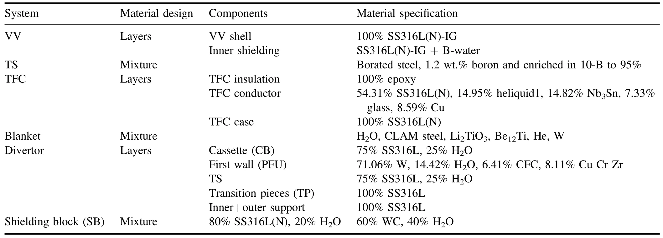
Table 1.Material composition in the CFETR system and components (unit: vol% specified if wt.%).
The densities and chemical compositions of the materials in the model were used based on the‘actual’mass determined from the CAD model.The PFUs are positioned in the inner vertical target (IVT), outer vertical target (OVT), dome and reflector plates.Tungsten was used as the first layer of monoblocks, combined with CuCrZr and CFC as inner and outer materials of the cooling pipe, respectively, based on their excellent thermal conductivity and mechanical strength at high operating temperatures when paired with water as a cooling medium.SS316L stainless steel with water cooling was used in the design of the CB and transition support (TS)as coolant manifolds to cool down and support the plasmafacing sections,which takes advantage of the unique chemical features and strong conductivity of the material to remove the neutron heat flux from the plasma.Both the inner and outer supports are made of SS316L.As shown in table 1,the whole neutronics model comprises a CB incorporated into the CFETR [2, 12].
For the divertor region components, the stainless steel SS316L(N)-IG was used for the materials of the VV shell and inner shielding layers,together with the borated water bonded with the TS.The outside was covered by the TFC as it is the last component of this design [13].The optimization of the materials used in the design has been tried to add more options for materials for the shielding block (SB), such as stainless steel and tungsten carbide (WC), and each in combination with water cooling was represented by various thicknesses, as seen in table 1 [2, 12–14].The design of the divertor region and evaluation of the nuclear responses have been started from the assessment of the divertor system components and then other systems around it.But, unfortunately, it was found not able to meet the safety requirements,which has thus led to modification of the design model.Addition of the SB at different thicknesses was tried to meet the design safety limits, as shown in figure 7.

Table 2.The operational scenario.
3.Calculation model and nuclear data library
One of the critical evaluations in the CFETR physical and engineering design is the neutronics performance.It is committed to resolving challenges, such as regular operation and shutdown of the CFETR reactor, scheduled and unscheduled maintenance and radioactive waste management [15].This analysis has been performed using the MCNP-5 [16, 17]coupled with FENDL 2.1.as the nuclear data library [18].It assumed the operational scenario as 1 to 1.5 GW range of fusion-power operation and a deuterium–tritium plasma source(n s−1)together with 14 years of regular operation with different fusion powers, as detailed in table 2.For this purpose, it has carried out the nuclear response of the divertor region system’s component, evaluated the divertor shielding capability and optimized the divertor region design.To reduce the computing time of the iterative calculations of the Monte Carlo simulation, the message parsing interface capability simulation was employed.Based on this, errors generated during calculation are satisfied using the station of the SHENMA cluster in the Institute of Plasma Physics of Chinese Academy of Sciences (ASIPP).The FMESH technique used 20 cm×20 cm mesh size to get the weight window added[19]to the MCNP format,and can evaluate the neutron flux in the material and design to be adjusted for accurate results.
4.Results
4.1.Nuclear response of the divertor system
The combined neutron and gamma fluxes can generate nuclear heating in the CFETR divertor system with total nuclear heating power under 1.5 GW fusion power for the 54 cassettes of 160.44 MW with a rate of 0.88 from the earlier CFETR design, and 10 MW for each 22.5° model.The nuclear heating density (NHD) for the divertor system components carried out is shown in table 3, as well as the comparison with the two earlier CFETR and ITER designs [20];were in a high subscription.Moreover, the nuclear heating power is 1×105,2.29×105and 4.55×10⁶W for the two reflectors and the TS, respectively.
The NHD (W cm−3) in one model sector has been charted for the whole divertor body,as shown in figure 3.The variations of the heat distribution that are directly concerned with the components’ locations from the plasma radiation source are shown clearly.The results were visualized using the ParaView post-processing code by converting the tally results to the VTK format [21].The highest values are in the upper parts of the PFUs and, for the CB, there are more than 0.1 MW cm−3under the dome umbrella.
For the radiation damage distribution, one piece of the cassette assemblies was closely studied to show the label number of segment parts for each divertor system component.As shown in figure 4,the map of a design system CB is in 17 parts and PFUs are in 23 parts.Each part is divided into two layers; the number is from the inner board area to the outboard portion of the divertor system model.The displacements per atom (dpa) and gas production charts followed the map segments’ design description.
Neutron flux from the plasma can generate irradiation damage to the materials by displacement per atom per one fusion-power year of operation (dpa/fpy).This is referred to as the threshold displacement energy of the component materials and the amount of neutron flux in the tally specification.The distribution of radiation damage in one model in figures 5(c) and (d) showed the maximum damage values to the PFU of 2.56 dpa and 3.35 dpa in tungsten material: both are located in the OVT.The cassette’s body was 6.32 dpa for the SS316L and 2.17 dpa for all the CBs, located behind the upper part of the OVT.Gas production distributions in the CB and PFU are shown in figures 5(a) and (b).Taking one piece of the cassette as an example, generally, the production of H is more than that of He,with the highest values distributed in the IVT, centered at the dome, OVT, and the CB under the upper part of the OVT and dome.
4.2.Divertor shielding capability
The neutron flux distribution withPf=1.5 GW is shown in figure 6(a).For the divertor system, the highest neutron flux reaches about 3×10¹⁴n cm−2s−1in the PFU, and the CB has about 3×10¹²n cm−2s−1; the neutron flux in the divertor region reaches more than 2×10¹¹n cm−2s−1for the TFC in the bottom area of the divertor.Moreover, there are a number of hot-spot areas, which means a high rate of neutron flux in the system’s components.The cassette’s exhaust hole passes more neutron flux, which might cause damage to the divertor region system’s materials (VV and TFC), indicating the divertor’s design is still not sufficient.
According to the flux distribution, as shown in figure 6(a),various significant adjustments and enhancements have been made to the CFETR divertor region design.The 3D neutronics model needs to be used to optimize the divertor shielding design by adding a plate to act as a shield at the bottom area of the CB, as shown in figure 7, combined with VV and cassette supports (inner and outer), and tested at different thicknesses of 20 cm and 35 cm, filled first with the SS316L and second,with the WC mixture material with water cooling, as shown in table 1.According to these options, the optimizations have been carried out to diagnose the design responses in all of the optimized options and to find out which one can meet the design limits.

Figure 3.Nuclear heating density (W cm−3) for the CFETR divertor system.

Figure 4.The segment numbers of the divertor system.

Table 3.The nuclear heating power of the divertor 22.5° model.

Figure 5.Radiation damage distribution in the divertor system.Gas production distributions (appm/fpy) in the PFU (a) and CB (b), and displacement damage distributions (dpa/fpy) in the PFU (c) and CB (d), in one piece of the divertor model.

Figure 6.Neutron flux distribution (n cm−2 s−1) in the divertor region in the initial design (a) and in the optimized design (b).
Based on neutron flux distribution in the divertor region,SBs are considered to insert in the space between the divertor and VV.Thickness and material specification effects on the SB’s shielding capability,structure and thickness of SBs were optimized.Generally, the results exhibited improvement in neutron flux distribution(n cm−2s−1)when compared with the initial design: the optimized design options starting from 20 cm can work effectively during the assumed operational scenario and are still under the design limits, as shown in figure 6(b) as an optimized design.To diagnose the efficiency of the SB options on allregion components, such as the VV system , the response of 1.5 GW as nuclear responses for one-year fusion power showed a considerable decrease in the VV materials after addition of the SB.The maximum NHD for the VV in the initial design was 1.85×10⁻¹W cm−3, located in an area behind the CB.By adding an SB of 20 cm thickness, the VV material has a maximum value of 2.16×10⁻²W cm−3for the SS316L block and 9.19×10⁻³W cm−3for the WC block.As shown in table 4,the maximum radiation damage and total NHD in the VV are also decreased after adding the SB.All the thicknesses of the WC materials added showed better response parameters than those of the SS316L.
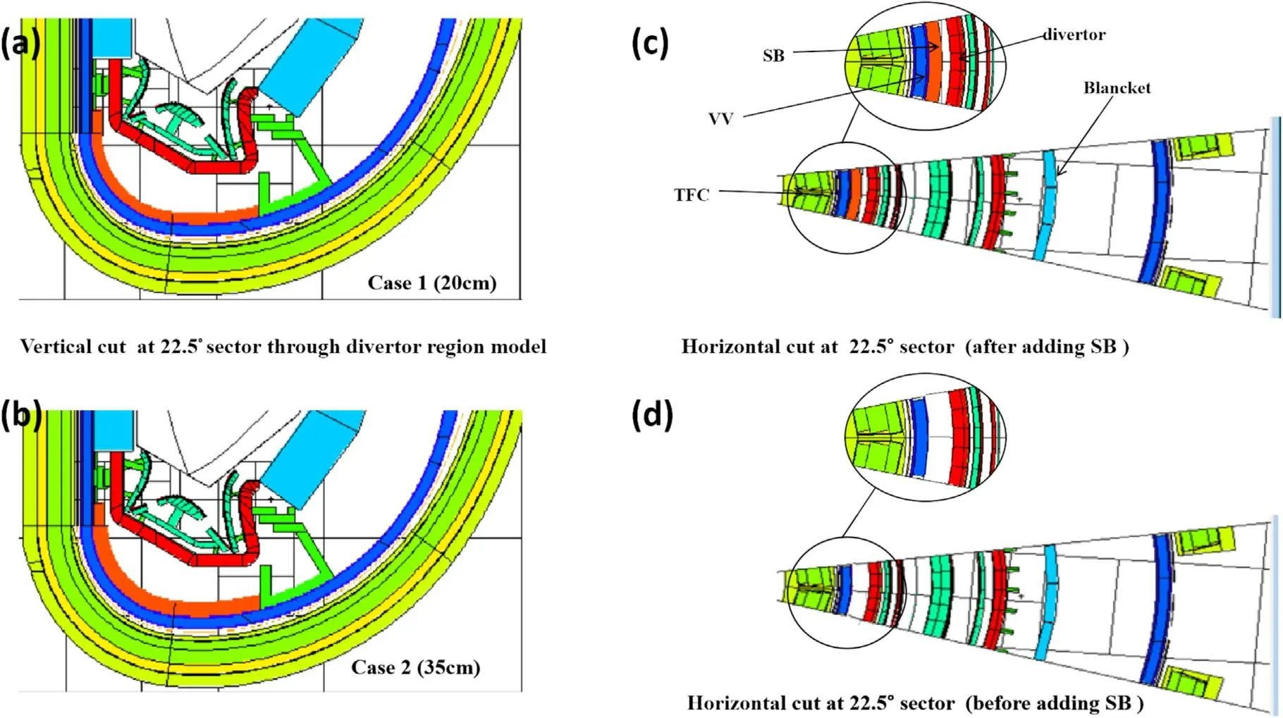
Figure 7.The 3D neutronics model for the options design of the optimized SB in the 22.5°sector.Case 1 for 20 cm thickness(a),case 2 for 35 cm thickness (b), horizontal cuts for the 22.5° sector at z=−500 cm after adding the SB (c) and horizontal cuts for the 22.5° sector at z=−500 cm before adding the SB (d).
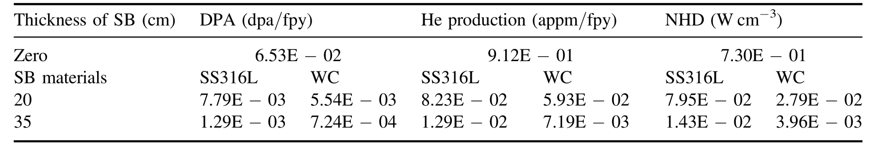
Table 4.Nuclear assessment for the VV.
The response of the NHD and neutron fluence for the TFC components case, insulator and conductor as the last layer in the design is considered as an essential system in the CFETR design to be approved.Setting the operation scenario at different fusion power per year following table 2, the maximum values in the initial design were 1.67×10¹⁹n cm−2and 1.68×10⁻³W cm−3of neutron fluence and NHD, respectively, for the TFC conductor.Moreover, the maximum value of fast neutron fluence in the TFC insulator was 3.06×10¹⁹n cm−2,and the NHD for the TFC case was 1.68×10⁻³W cm−3in an area under the CB.
The TFC components system showed a good response after we optimized the design, and starting from the 20 cm thickness demonstrated an excellent performance until 14 years of reactor life;the maximum neutron fluence values for the TFC conductor are 1.13×10¹⁸n cm−2for SS316L and 8.66×10¹⁷n cm−2for WC.Also,the NHD was decreased to 1.18×10⁻⁴W cm−3for SS316L and 8.56×10⁻⁵W cm−3for WC upon the maximum response.With regard to the 35 cm thickness, the TFC components have a great response to various materials from the simulation results carried out,as shown in table 5.
In summary, the optimized design showed the distribution of fast neutron fluence and the NHD in the TFC, which all have significant responses.Meanwhile, the maximum values and 14 year operation scenario in different fusion power per year satisfied the ITER design limits, which start from 20 cm to 35 cm.The performance of WC showed the best and lowest values compared with SS316L due to its unique properties that enabled it to moderate the amount of neutron energy flux in this area after being moderated by the divertor materials.After the vast options and comparisons,we can now approve this optimized design, and present it as a reliable option to engineering designers, to optimize the divertor region and deal with the hot spots in this area,due to its sufficient performance that will enable it to meet the safety limits, as clearly shown in table 5 [4, 22, 23].
5.Summary and conclusion
The CFETR is still under development and will be modified until it reaches a steady performance status and can carry out duties with greater efficiency.As a result, the neutronics performance of the CFETR facility and its components, particularly the bottom half of the reactor, will be affected, such as the performance of the divertor region.The nuclear heating values, the neutron flux distribution and radiation damage to the material components are the primary elements used to evaluate the responses of the system region, which are also required to meet the ITER safety limits.

Table 5.Nuclear responses of the TFC and referred ITER design limits.
This study also presents the nuclear evaluation of a modified divertor region;the nuclear heating in the divertor system under 1.5 GW fusion power reaches 160.44 MW and 10 MW for the 22.5°model.The PFU’s and CB’s radiation damage level has a nearly linear correlation with the threshold displacement energy of the component materials because they face the neutron flux emitted from the plasma.The neutron flux distribution in the CB reaches 3×10¹²n cm−2s−1and 2×10¹¹n cm−2s−1for the TFC behind the divertor area: such a high rate of neutron leakage indicates the divertor design capability is not sufficient.The design is optimized by adding the SB in the bottom area of the divertor system to protect the VV and the magnet system and its nuclear performance was evaluated.The optimized results show an excellent response in the NHD for the TFC case with 35 cm SB thickness, almost 0.3% less than the initial design.Moreover,the NHD in the TFC case and conductor that accumulated to neutron fluence in the conductor and insulator in the 14 year operation scenario in different fusion power per year did not exceed the referred ITER design limits.This research attempts to contribute to the physical and engineering design and thermohydraulic and mechanical analysis of the CFETR by providing relevant information for the improvement of its design performance.Future work is still needed to optimize the divertor region,particularly the portion not covered by the SB.It has somewhat higher risks than that behind the SB; the improvements provided herein will be helpful in leading a more comprehensive design of the CFETR divertor and blanket, as well as additional shielding systems.
Acknowledgments
This work was supported by the National Key Research and Development Program of China(Nos.2017YFE0300500 and 2017YFE0300503).
ORCID iDs
猜你喜欢
杂志排行

Plasma Science and Technology的其它文章
- Numerical simulation of nanosecond laser ablation and plasma characteristics considering a real gas equation of state
- The propagation dynamics and stability of an intense laser beam in a radial power-law plasma channel
- Effect of edge magnetic island on carbon screening in the J-TEXT tokamak
- Relativistic effect on synergy of electron cyclotron and lower hybrid waves on EAST
- Influence of the X-point location on edge plasma transport in the J-TEXT tokamak with a high-field-side single-null divertor
- A simulation study of protons heated by left/right-handed Alfvén waves generated by electromagnetic proton–proton instability