Embedding any desired number of coexisting attractors in memristive system∗
2021-12-22ChunbiaoLi李春彪RanWang王然XuMa马旭YichengJiang姜易成andZuohuaLiu刘作华
Chunbiao Li(李春彪) Ran Wang(王然) Xu Ma(马旭)Yicheng Jiang(姜易成) and Zuohua Liu(刘作华)
1Jiangsu Collaborative Innovation Center of Atmospheric Environment and Equipment Technology(CICAEET),Nanjing University of Information Science&Technology,Nanjing 210044,China
2School of Artificial Intelligence,Nanjing University of Information Science&Technology,Nanjing 210044,China
3State Key Laboratory of Coal Mine Disaster Dynamics and Control,Chongqing University,Chongqing 400044,China
Keywords: offset boosting,attractor doubling,attractor self-reproducing,memristive system
1. Introduction
Memristor is regarded as a new component for circuit design,which has a specific voltage–current restriction with fingerprint characteristics of 8-like pinched hysteresis loop.[1–5]Because of the nonlinear feature,memristor brings chaos possibility even in a very simple system.[6–13]As a memory component, the dynamical states in its networks can characterize various patterns in information system. Coexisting attractors controlled by a direct switch or simple hardware configuration could be helpful for state representation and conducive to the integration of storage and calculation. As a result, it is valuable to explore the dynamics of a simple memristive node and control its states for information processing.
Multistability in memristive systems has been exhaustedly explored,among which extreme multistability[14–20]and coexistence with infinitely many attractors[21–24]seem especially striking. In the area of information engineering, the number of coexisting attractors seems to be an important issue for effective information representation or signal acquisition. For memristive chaos-based application,there are two challenges lying in this direction,one of which is to find a simple structure for hosting a memristor to give offset boostable chaos while the other one aims to get its attractor controlled by a single knob or hardware configuration. If we ignore the real products of memristors and model a freely defined memristor with representative inherent fingerprints, such a threedimensional(3-D)memristive system is thereby not far away from our goal. In fact, people can investigate those existing systems and try to find the distinct memristor variable dependence. Following with a further nonlinear reforming, a fresh 3-D memristive system is derived for embedding coexisting attractors,as shown in Fig.1.
Offset control is the fundamental principle for attractor doubling[25–27]and attractor self-reproducing.[28–30]By introducing multiple piecewise-like functions into a seed system,the dominant dynamics generally finds its way for attractor self-reproducing. It was pointed that the substitution of a proper absolute value function gives robust attractor doubling in the routine of symmetrization while the periodic function repeats the desired dynamics in a direct easy way for attractor self-reproducing. Attractor-doubling represents a direct double multiplication while the attractor self-reproducing is helpful for direct cumulative counting. Two regimes of attractor embedding could be applied for effective information representation or even numerical calculating. For a memristive system,system-based attractor doubling and self-reproducing preserve the fundamental system dynamics without changing the architecture and memristor component. The new born attractors stand by in system space as desired depending on the attached function substitutions and provide broad possibilities for information processing in some way.
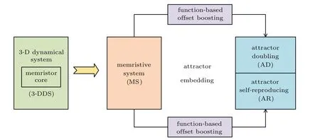
Fig.1. Nonlinearly reforming for embedding any number of coexisting attractors.
In this work,any number of coexisting attractors in a 3-D memristive system are obtained from a very direct offset-based processing. In Section 2, a simple 3-D memristive system is derived from an existing variable boostable system.[31]In Section 3, any number of coexisting attractors are embedded into the derived memristive system in the dimension of system variable with two different regimes: attractor doubling and attractor self-reproducing. The former provides a direct multiplication control while the latter resorts to the combination of signum and periodic function. In Section 4,circuit simulation is completed for physical verification. In fact, coexisting attractors stand in phase space can be recognized by an exact initial condition. Corresponding discussion is wrapped in the last section.
2. A unique offset-boostable 3-D memristive system
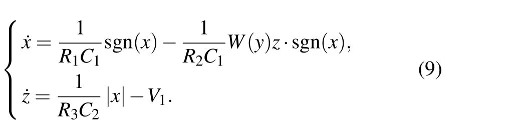
It is found that system(1)(VB6)[31]could be reformed to host a memristor,which gives chaos as system(2),
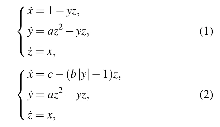
where the following memristor is introduced in the first dimension:
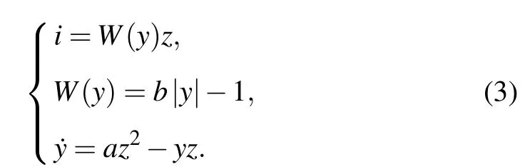
Whena=0.6, the memductance and pinched hysteresis loop are plotted in Fig.2.Here the variableyis regarded as the internal variable and the introduced memristor has piecewise linear memductance.
Whena= 0.6,b= 1, andc= 1, memristive system (2) shows chaotic oscillation with Lyapunov exponents(0.1793,0,−1.1809) and Kaplan–Yorke dimensionDKY=2.1518 under initial condition(−1,1,−1),as shown in Fig.3.Note that the internal variableyand system variablesxandzall exhibit chaotic oscillation.
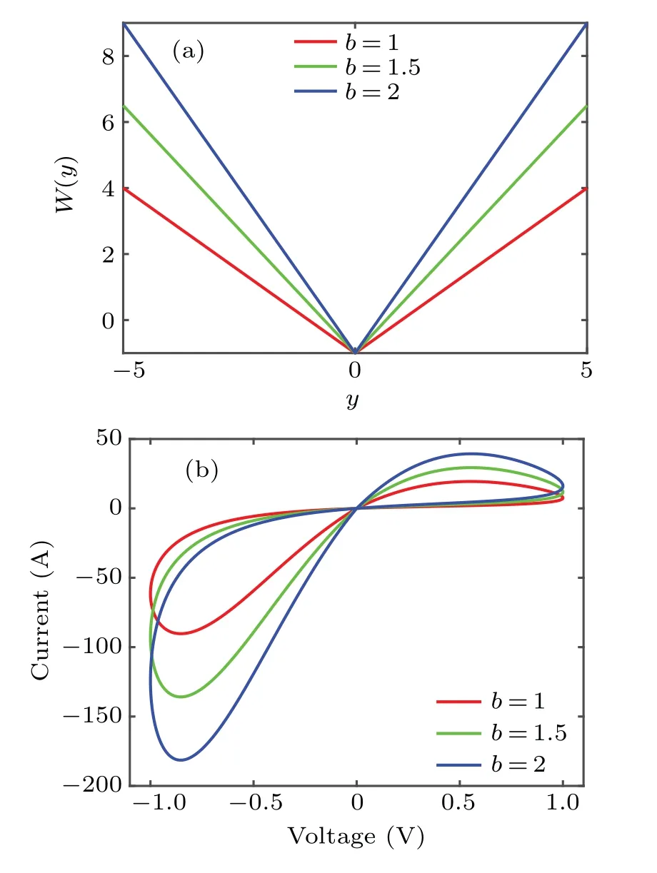
Fig.2. The memductance and pinched hysteresis loop with sinusoidal excitation under f =0.1: (a)memductance,(b)pinched hysteresis.
System(2)is offset boostable,which can be proved with a direct substitution likex −→x+m. Moreover, in the specifically introduced memristor the inherent property of voltagecurrent relation is determined by the two parametersaandb.It turns out that the parameterbrescales the amplitude of system variablexnegatively while the frequency proportionally in a limited region as shown in Fig. 4, which has never been reported in other memristive systems. The evolvement of amplitude and frequency can be seen directly from the waveform and frequency spectra, as shown in Fig.5. To understand the function of parameterb,here take a substitution

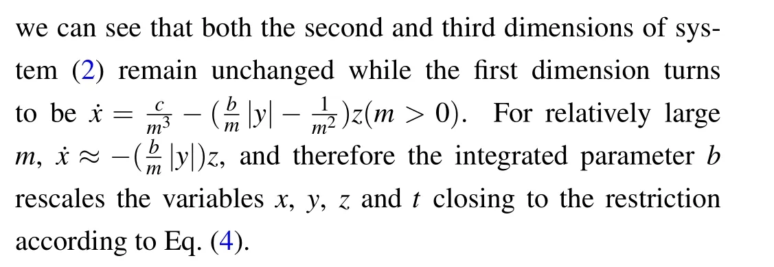
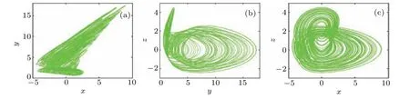
Fig.3. Chaotic attractor in system(2)with a=0.6,b=1,c=1,and initial condition(−1,1,−1): (a)x–y,(b)y–z,(c)x–z.
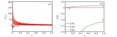
Fig.4. Dynamical evolvement of system(2)with a=0.6,c=1,IC=(−1,1,−1): (a)bifurcation behavior,(b)Lyapunov exponents.
Fig.5. Chaotic oscillation of system(2)with a=0.6,c=1,IC=(−1,1,−1): (a)chaotic signal x(t),(b)frequency spectrum.

Fig.6. Dynamics of system(2)with a=0.6,b=1,IC=(−1,1,−1): (a)bifurcation diagram,(b)Lyapunov exponents.
Moreover, system (2) exhibits robust chaos according to the parameterc, which also rescales the amplitude of system variablexin a quasilinear way with occasionally inserted periodic windows,as shown in Fig.6. Whencincreases in region[0,15],only a couple of periodic oscillations break in triggering the collapse of the Lyapunov exponents. All the above analysis shows that system(2)is unique in terms of parameter sensitivity. Two parameters, namely, system parametercand memristor parameterbboth show their independent function of amplitude control. Memristor parameterbalso brings time rescaling for Lyapunov exponent modification.
3. Two regimes of attractor embedding
The coexisting attractors can be controlled by functionbased offset boosting. However, one is resort to attractor doubling,and the other is resort to attractor self-reproducing.Therefore, these two approaches bring coexisting attractors with different scales. Attractor doubling can be used to simulate the key processing for high bit generation in binary number representation while attractor self-reproducing can be applied for representation of numerical accumulation. Attractor doubling introduces more parameters for attractor embedding and resorts to system modification more violently. These parameters form control gates by which the number of coexisting attractors is determined by the series[32]if coexisting attractors are doubled more than one times. Attractor self-reproducing seems easier for embedding more attractors even more to infinity. But this seems to out of control if not sufficient control gates are planted. In fact,in both routines of attractor embedding, sufficient offset gates are necessary for controlling the number of coexisting attractors. Only by this, any one of the embedded attractors can be visited by a selected initial condition gate accordingly.
3.1. Attractor doubling
The direct substitution of the absolute value function can make the coexisting attractors doubled. The single linear termxin the third dimension of system (2) makes the dimensionxeasily offset boostable, leaving a convenient conversion for attractor doubling. Substitutingxwith|x|−das

The doubled attractors are controlled with desired distance by the control gate ofd. Note that small gatedmakes the coexisting attractors be linked together forming pseudodouble-scroll. Then a pseudo-double-scroll attractor is captured when coexisting attractors get linked together because of the connected basins of attraction. The doubled coexisting attractors stand in phase space in the dimension ofx,as shown in Fig.7. As a result,the derived system(5)now turns to be a symmetrical system hatching coexisting symmetrical pairs of attractors or pseudo-multiple-scroll attractors.
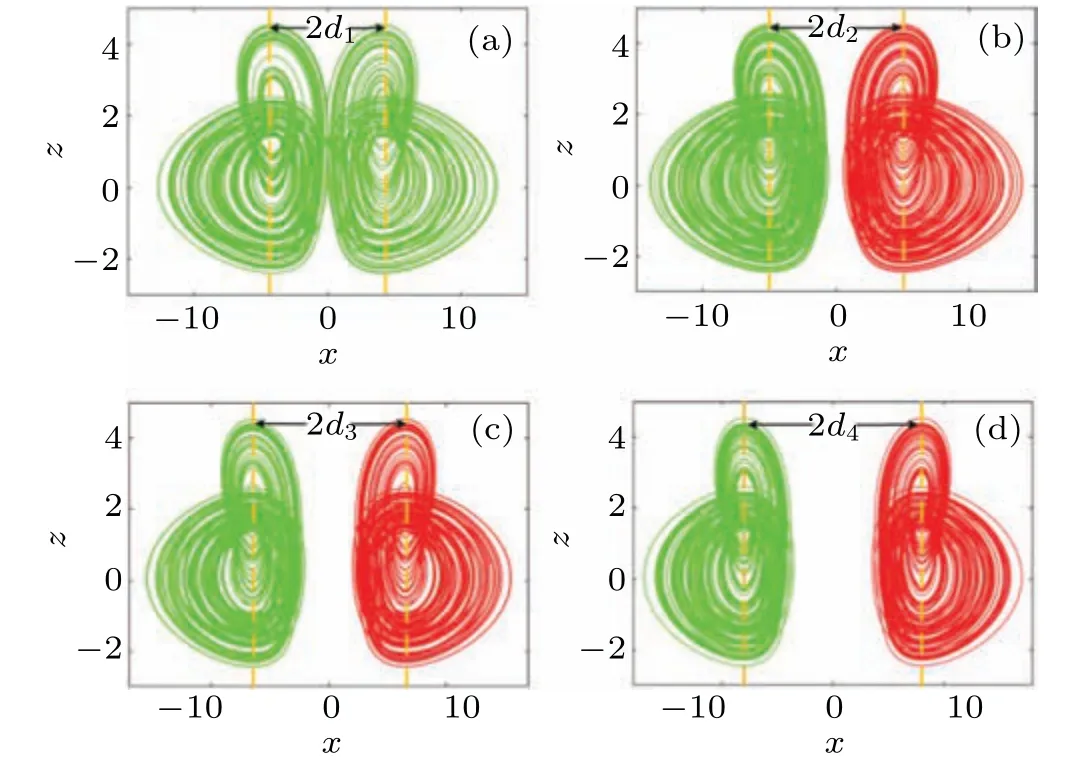
Fig. 7. Embedded attractors in system (5) with a=0.6, b=1, c=1 under various control gates. IC=(1,1,−1)is red and IC=(−1,1,−1)is green:(a) d1 =4.11 (pseudo-double-scroll attractor), (b) d2 =5, (c)d3=6.5,(d)d4=8(double coexisting attractors).
Furthermore,this operation can be repeated in the dimensionz, but this will destroy the feedback of the originally introduced memristor. For doubling the attractors according to the dimension ofz,the derivative of internal variable turns to be associated with the absolute function with offset gatee,and the following equation is obtained:
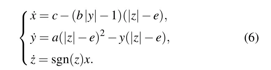
The substitution ofzwith|z|−echanges the original system more drastically. Doubled attractors locate in the dimension ofzas predicted, as shown in Fig. 8. Since the system variable is more controllable than the memristor,this transformation does not bring too much trouble since the derivative ofycomes from the feedback ofyand the flexible function of system variablezeven though we see that this transformation does not fully utilize the property of easy offset boosting.
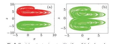
Fig. 8. Coexisting attractors in system (6) with a=0.6, b=1, c=1,IC=(−1,1,1) is red and IC=(−1,1,−1) is green: (a) a symmetric pair of coexisting attractors under control gate e=4,(b)pseudo-doublescroll attractor under control gate e=2.05.
Doubling coexisting attractors can also be executed in both dimensions ofx–z, where two control gatesdandeare necessary for settling any of the attractors to desired position as in the following equation:
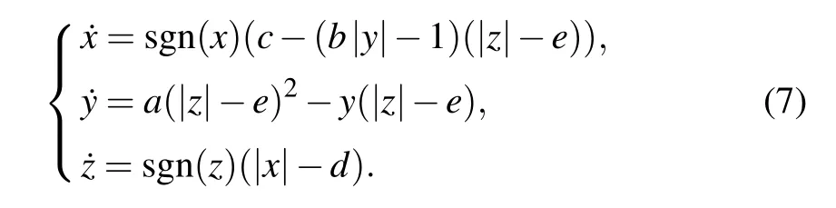
Smaller control gatedmakes coexisting attractors link together in the dimension ofxforming two pseudo-two-scroll attractors, while combined small control gateeputs the doubled pseudo-two-scroll attractors together forming a pseudofour-scroll attractor, as shown in Fig. 9. Corresponding signal waveforms are plotted in Fig. 10. Note that two control gates should be arranged with two newly introduced signum functions. The process of attractor doubling depends on the revise of the system structure. Two signum functions sgn(x),sgn(z)and two control gatesd,ein two absolute value functions embed at most four coexisting attractors. For more attractors, the substitution of the absolute value function needs to be repeated, bringing more control gates and switching functions.[32]However, attractor embedding can turn to another way, where the property of offset boosting can be used for more convenient attractor embedding. In the following,we discuss how to embed any desired number of attractors by introducing a periodic function.
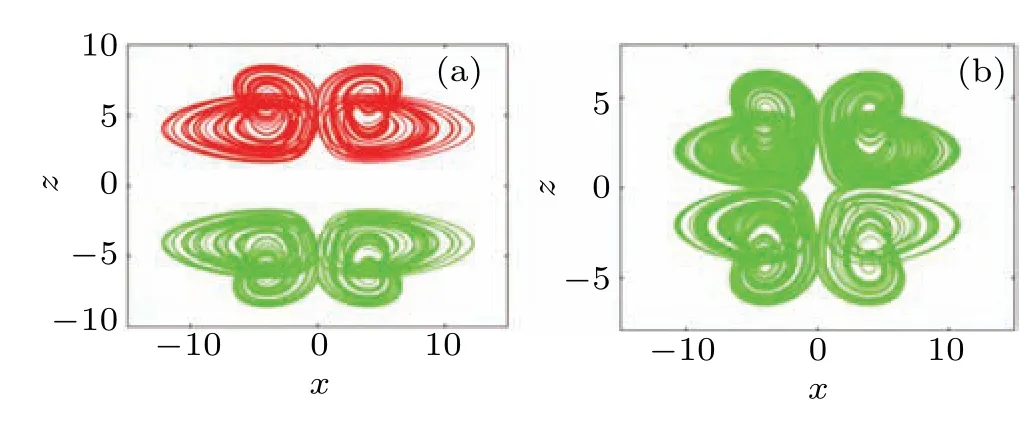
Fig. 9. Embedded attractors in system (7) with a=0.6, b=1, c=1,IC=(−1,1,1) is red and IC=(−1,1,−1) is green: (a) a symmetric pair of coexisting pseudo-two-scroll attractors under control gates d=4,e=4,(b)pseudo-four-scroll attractor under d=4,e=2.

0Fig.10.Waveform of coexisting oscillations in system(7)with a=0.6,b=1, c=1, IC=(−1,1,1)is red and IC=(−1,1,−1)is green: (a)d=4,e=4(coexisting pseudo-two-scroll attractors),(b)d=4,e=2(pseudo-four-scroll attractor).
3.2. Attractor self-reproducing
The above attractor embedding has a discrete scale,where the number of coexisting attractors depends on the times of absolute-value-function substitution. Each operation needs an extra function introducing. In fact, infinitely many attractors are available by introducing a periodic trigonometric function to the offset boostable variable. Based on this,further control for embedding any number of coexisting attractors is resort to the modification of the periodic function. Applying signum function,the number of coexisting attractors can be controlled by newly introduced offset gate. Memristive system(2)has a single system variablexin the right hand,and can be modified as
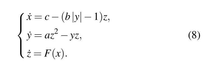
WhenF(x)=1.25sin(0.2x)(sgn(x)+1)(sgn(−x+d)+1), coexisting attractors can be controlled by the offset gate ofd. Comparing with the approach based on system(4)(with one absolute value function and one signum function)and system (7) (with two absolute value functions and two signum functions), here in system(8), a sinusoidal function modified by two signum functions provides a free control of any coexisting attractors. The principle can be clearly indicated by the curve of the control function shown in Fig.11. Here the control gatedselects the number of coexisting attractors. Positivedoutputs coexisting attractors in positive direction and vice versa. As shown in Fig. 12, a couple of coexisting attractors are controlled by control gatesd. If we want to select coexisting attractors in desired region,two independent control gatesdshould be set according to the two signum functions. More control gates pose more precise and flexible control. Mixed control can be obtained if an extra substitution of the absolute value function in the dimension ofzis made,and correspondingly the selected attractors will get doubled in thezdimension. One can do this for his convenience. Control gatedshould be selected according to the size of an attractor.
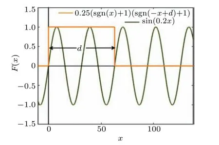
Fig.11. The curve of the control function for attractor embedding.
Furthermore, the functionF(x) can be replaced by a piecewise linear function and other trigonometric functions.For example, tangent function can be applied into system(8)for hatching coexisting attractors according to its period.WhenF(x) = 72tan(0.05x), infinitely many coexisting attractors are born distributing in phase space with interval of 20πbetween any of two attractors. Applying more control gates based on signum function, more than that, embedded coexisting attractors can be edited in a more flexible way. For example, whenF(x)=1.25sin(0.2x)(sgn(x)+1)(sgn(−x+d1)+1)+4.5tan(0.05x)(sgn(x−d2)+1)(sgn(−x+d3)+1),embedded attractors are edited in region of [0,d1] with interval of 10πand [d2,d3] with interval of 20π, as shown in Fig. 13. Coexisting attractors can be selected and edited by choosing any combination of periodic trigonometric function and signum function.Control gate leaves a convenient channel for attractor group selection while initial condition gate realizes the precise positioning of a desired attractor. However,the control gate has priority over the initial condition.
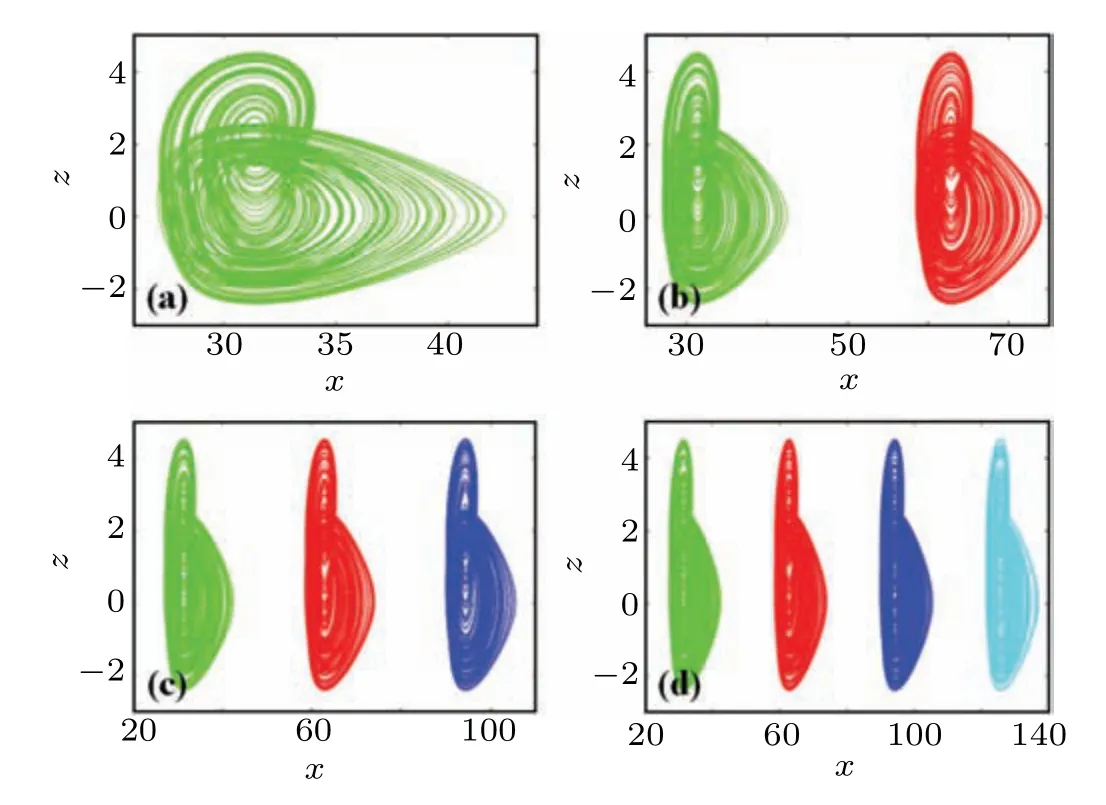
Fig. 12. Embedded coexisting attractors in system (8) with F(x) =1.25sin(0.2x)(sgn(x)+1)(sgn(−x+d)+1), a = 0.6, b = 1, c = 1,IC=(1+10π,1,−1)is green,IC=(1+20π,1,−1)is red,IC=(1+30π,1,−1)is blue and IC=(1+40π,1,−1)is cyan:(a)d=12+10π,(b)d=12+20π,(c)d=12+30π,(d)d=12+40π.
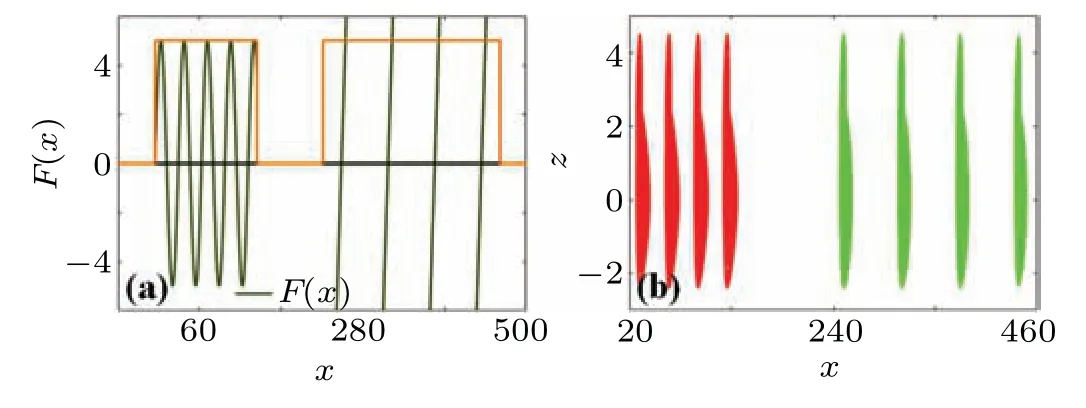
Fig. 13. Control function and embedded coexisting attractors in system (8) with F(x) = 1.25sin(0.2x)(sgn(x) + 1)(sgn(−x + d1) + 1) +4.5tan(0.05x)(sgn(x −d2)+1)(sgn(−x+d3)+1), d1 = 12+40π, d2 =−25 + 80π, d3 = 25 + 140π, a = 0.6, b = 1, c = 1, IC = (1 +10π/20π/30π/40π,1,−1)are red,IC=(1+80π/100π/120π/140π,1,−1)are green: (a)control function,(b)embedded attractors.
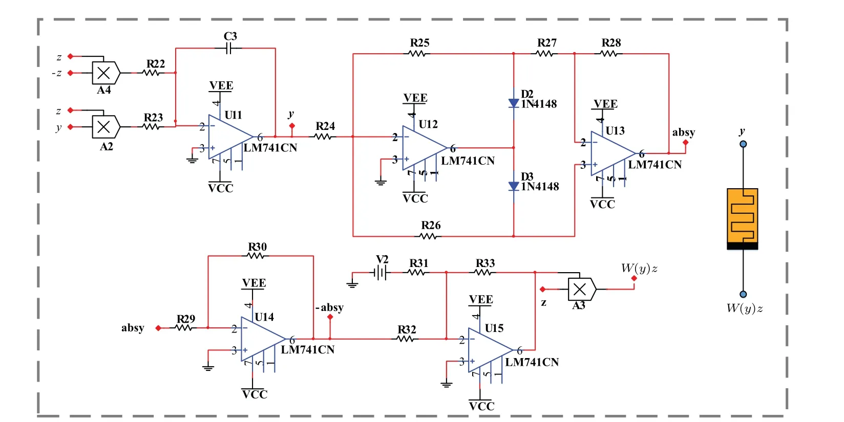
Fig.14. The analog equivalent circuit schematic of memristor(3).
4. Circuit implementation
To verify the above system design for attractor embedding,circuit-based experiment is realized for further observation. To realize system(2),a memristor simulator is designed in Fig. 14. Here the derivative of internal variableyis connected with system variablez. Therefore system(5)for attractor doubling turns to be
Circuit modules associated with the absolute value function are constructed for attractor doubling. According to the parameters combined with a time scale for attractor showing in oscilloscope, circuit parameters are selected in Fig. 15 asC1 =C2=C3=10 nF,R1=R2=R3=R4=R10=R23=R31 =R32=R33= 10 kΩ,R5=R6=R7=R8=R11=R12 =R13=R14=R15=R16=R17=R18=R19=R20=R21=R24=R25=R26=R27=R28=R29=R30=100 kΩ,R9=140 kΩ,R22=16.67 kΩ,V2=1 V. Like the attractors plotted in Fig.7,the pseudo-double-scroll attractor and coexisting attractors are captured as shown in Fig.16.
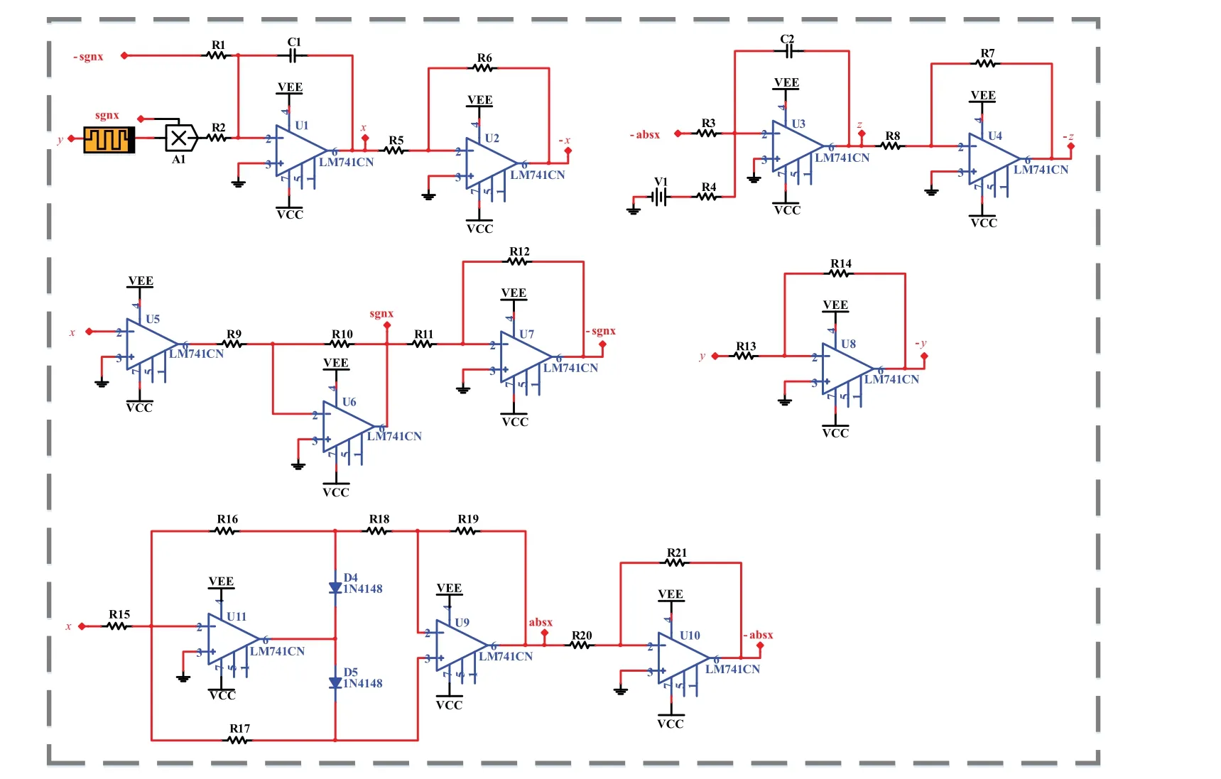
Fig.15. Circuit schematic of memristive system(5).
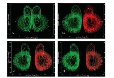
Fig. 16. Coexisting attractors in system (5) with V1 =1 V, IC=(1,1,−1) is red and IC=(−1,1,−1) is green: (a) pseudo-double-scroll attractor under V1=4.11 V,(b)–(d)a symmetric pair of coexisting attractors under V1=5 V,V1=6.5 V,and V1=8 V.
For doubling coexisting attractors in the dimensions ofxandz, more modules are applied for absolute value function realization,the revised system(7)turns to be the circuit with the following equation:
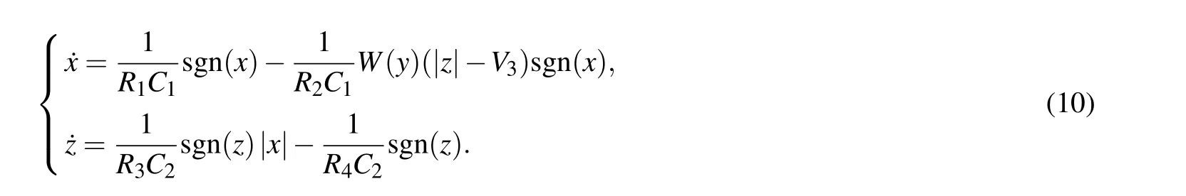
To realize system(10),a memristor simulator is designed in Fig. 17. According to the parameters combined with a time scale for attractor showing in oscilloscope, circuit components in Fig.18 areC1=C2=C3=10 nF,R1=R2=R3=R10=R23=R31=R32=R33=R34=R35=R36=R37=R38=R47=10 kΩ,R5=R6=R7=R8=R11=R12=R13=R14=R15=R16=R17=R18=R19=R20=R21=R24=R25 =R26=R27=R28=R29=R30=R39=R40=R41=R42=R43=R44=R45=R48=R49=100 kΩ,R4=2.5 kΩ,R9=R46= 140 kΩ,R22= 16.67 kΩ,V2= 1 V. Like the embedded attractors and waveform of oscillations plotted in Figs. 9 and 10, the pseudo-double-scroll attractor, pseudofour-scroll and waveform of oscillations are captured as shown in Fig.19.
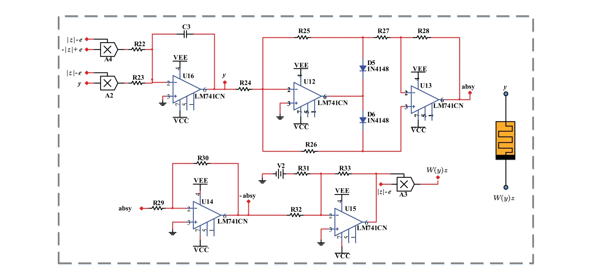
Fig.17. The analog equivalent circuit schematic of the memristor.
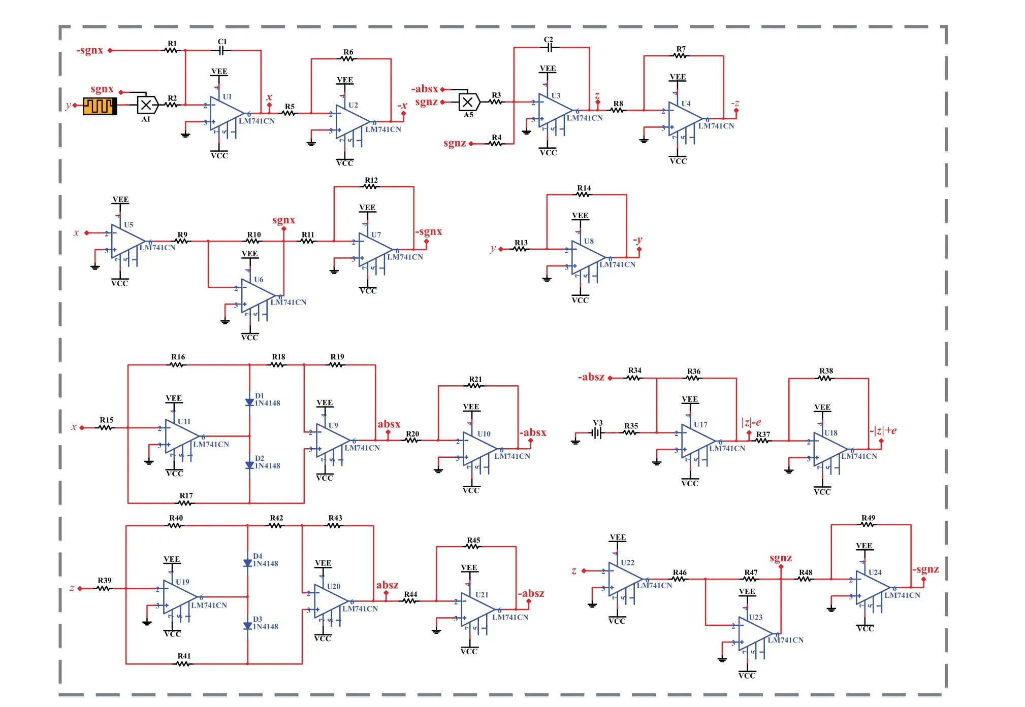
Fig.18. Circuit schematic of memristive system(7).
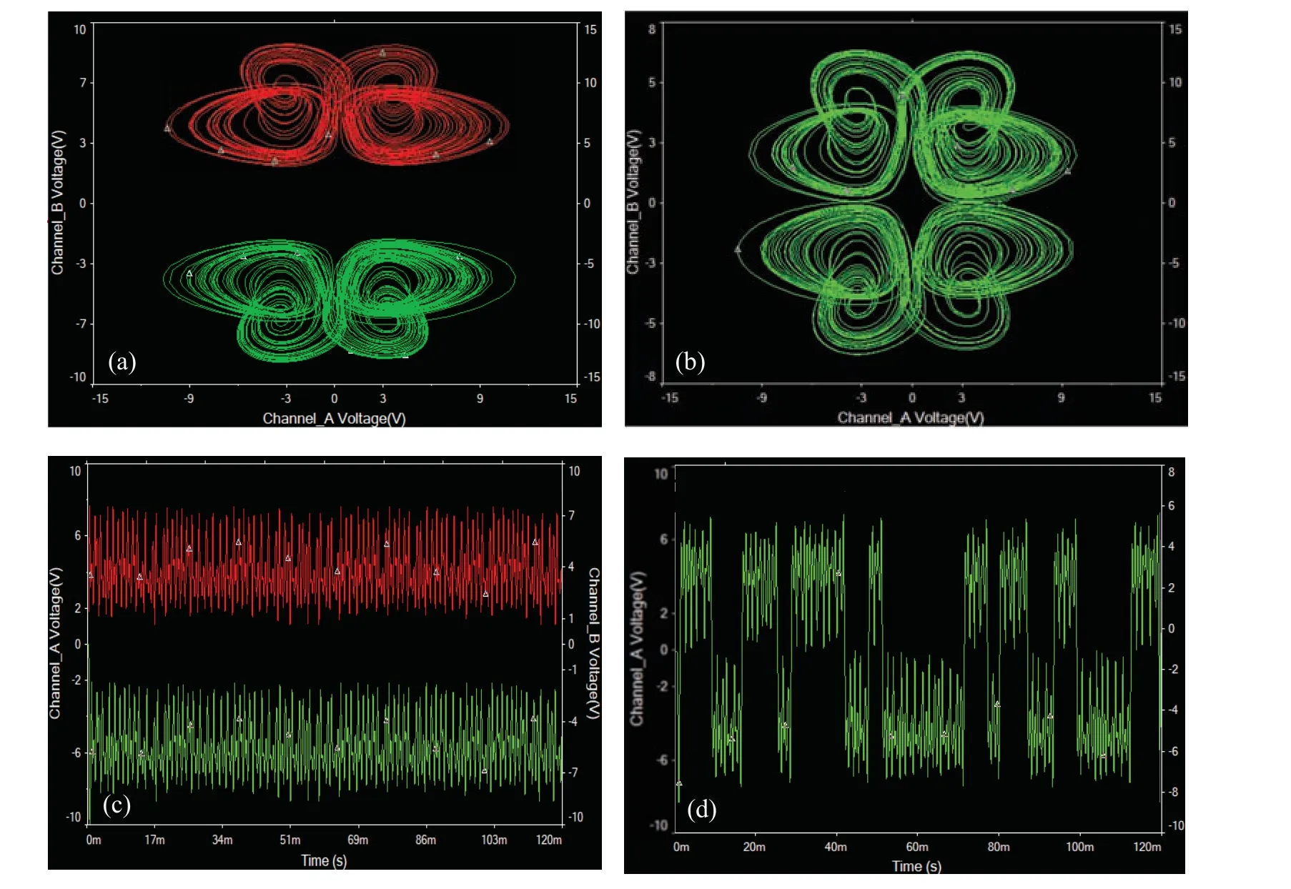
Fig. 19. Attractors and chaotic signals in circuit (10) with V2 =1 V, IC=(−1,1,1) is red and IC=(−1,1,−1) is green: (a) a symmetric pair of coexisting pseudo-double-scroll attractors with V3=4 V,(b)pseudo-four-scroll attractor with V3=2 V,(c)a symmetric pair of chaotic signals under V3=4 V,(d)chaotic signal under V3=2 V.
5. Discussion and conclusion
Flexible memristor definition can make great contribution for constructing a 3-D chaotic memristive system,where additional nonlinearity typically does not destroy the fundamental dynamics inherited from the seed system. In fact,we can construct more 3-D chaotic systems from the existing 3-D manifolds or by defining more mathematical models of memristor.Memristor introducing in a variable-boostable system brings more convenience for attractor embedding. In this work,from the view of attractor embedding,a simple 3-D memristive system is derived, in which the basic property of variable boosting is not destroyed. It brings great convenience for attractor doubling. Besides this, periodic trigonometric function substitution makes the attractor self-reproducing in the dimension of offset boostable variable more conveniently.A simple absolute value function substitution combined with a switch function realizes attractor doubling. Doubling coexisting attractors depends on the operation of function substitution in which the absolute value function determines the intervals and signum function provides necessary polarity balance. Absolute value functions and other periodic trigonometric functions can be applied for attractor embedding with any number of coexisting attractors. There is an obstacle standing in the way of attractor doubling,which is how to realize the substitution of the absolute function in a simple replicable way. Periodic trigonometric function combined with signum function provides an easy way for attractor embedding and control. Further work aiming to this direction is expected in the near future.
杂志排行

Chinese Physics B的其它文章
- Transient transition behaviors of fractional-order simplest chaotic circuit with bi-stable locally-active memristor and its ARM-based implementation
- Modeling and dynamics of double Hindmarsh–Rose neuron with memristor-based magnetic coupling and time delay∗
- Cascade discrete memristive maps for enhancing chaos∗
- A review on the design of ternary logic circuits∗
- Extended phase diagram of La1−xCaxMnO3 by interfacial engineering∗
- A double quantum dot defined by top gates in a single crystalline InSb nanosheet∗