Particle flux characteristics of a compact high-field cascaded arc plasma device
2021-11-30XiaogangYUAN袁小刚HaishanZHOU周海山HaodongLIU刘皓东BoLI李波YongWANG王勇LeiCHANG苌磊XinYANG杨鑫ChuangWANG汪闯LupengZHANG张潞鹏andGuangnanLUO罗广南
Xiaogang YUAN(袁小刚),Haishan ZHOU(周海山),Haodong LIU(刘皓东),Bo LI (李波), Yong WANG (王勇), Lei CHANG (苌磊), Xin YANG (杨鑫),Chuang WANG (汪闯), Lupeng ZHANG (张潞鹏) and Guangnan LUO (罗广南)
1 Institute of Plasma Physics, HFIPS, Chinese Academy of Sciences, Hefei 230031, People’s Republic of China
2 University of Science and Technology of China, Hefei 230026, People’s Republic of China
Abstract A new compact cascaded arc device for plasma-wall interaction study is developed at the Institute of Plasma Physics, Chinese Academy of Sciences.A magnetic field up to 0.8 T is achieved to confine plasmas in a 1.2 m long and 0.1 m diameter vacuum chamber.Gas fluid type analysis in this compact vacuum system was done under high particle flux condition.The gas pressure obtained by calculation was consistent with the measurement result.Continuous argon plasma discharge with ion flux of ∼0.5 × 1024 m−2 s−1 is successfully sustained for more than 1 h.The effects of magnetic field configuration, gas flow rate, and discharge arc current on the ion flux to target were studied in detail.
Keywords:cascaded arc plasma,plasma-wall interaction,ion flux,vacuum design,linear plasma device
1.Introduction
The plasma-facing material of divertor will be subject to high particle flux up to 1024–1025m−2s−1in fusion reactors like ITER [1].The evaluation of the plasma-facing material performance under such high particle flux is necessary.To support the R&D of China Fusion Engineering Test Reactor[2],a large superconducting linear plasma testing facility will be built to evaluate candidate plasma-facing materials and component mockups in the Comprehensive Research Facility for Fusion Technology project [3].Due to the capacity to produce high density plasma,cascaded arc plasma sources are selected to simulate the divertor plasma stream.Plasma-wall interactions (PWI) experiments with high particle flux have been performed in cascaded arc source type linear plasma devices such as Magnum-PSI[4],Pilot-PSI[5],CIMPLE-PSI[6],SCU-PSI[7],and DUT-PSI[8].It has been demonstrated that the achievement of large ion flux requires both high magnetic field and huge gas fueling rate (typically several to tens of standard liters per minute (SLM)).The plasma expands from the nozzle and goes through a stationary shock,after which the plasma expands with subsonic velocity.The plasma density increases with the decrease of velocity.To avoid strong plasma recombination in the chamber, a relatively low operational gas pressure is required.Thus, the cascaded arc source is typically installed in a chamber with large diameter for the purpose of achieving high gas conductance.As a result,the inner diameter of the magnet needs to be large and the typical steady-state magnetic field at the center of the discharge chamber cannot exceed 0.5 T unless superconducting coils are installed, like Magnum-PSI [4].
However, it is still attractive to achieve high magnetic fields with conventional water-cooled copper magnet due to its low cost.That may lead to a limitation of the diameter of vacuum chamber.In such a compact vacuum chamber, the shock becomes narrow with the decrease of mean free path resulted from insufficient fluid conductance [9, 10].The impacts on plasma operation are not clear yet.In this work,a new compact cascaded arc plasma device with a magnetic field up to 0.8 T aiming for plasma source testing is developed.Argon (Ar) plasma discharge under the flux of∼0.5 × 1024m−2s−1for 1 h is demonstrated.The ion flux under different magnetic field configurations, discharge currents, and gas flows are also analyzed.
2.Experime ntal setup
A new cascaded arc plasma device (as shown in figure 1) is developed at the Institute of Plasma Physics, Chinese Academy of Sciences.This machine consists of a compact vacuum chamber made of 316 l stainless steel with a diameter D of 0.10 m and a length L0of ∼1.2 m, three independently controlled solenoid coils, a cascaded arc source, an actively cooled target with a distance L1of 0.52 m and a full range vacuum gauge.A roots pump with a pumping speed of 4500 m3h−1and a mechanical pump with a pumping speed of 630 m3h−1are employed to evacuate the discharge chamber.A background pressure of 0.1 Pa can be achieved within a few minutes.The reference axis is positioned at the end of the plasma source as shown in figure 1.
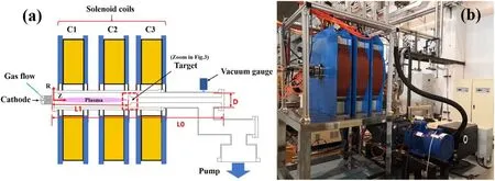
Figure 1.(a) A schematic drawing and (b) a picture of the new compact cascaded arc plasma device.
A one-cathode cascaded arc source, which is modified from the three-cathode source concept of Pilot-PSI and Magnum-PSI [11, 12], is employed to produce plasma, as shown in figure 2.To avoid the double arc problem in plasma discharge,four copper plates are used to separate the cathode and anode.Polyimide film and O-rings are selected for insulation and seal.The diameter of the discharge channel has a distinct impact on plasma deposition power.The size of the cathode determines the discharge lifetime and maximum operation current [13, 14].The cathode is made of tungsten alloy because of its high melting point and electron emissivity.Moreover,a copper anode is mounted on the end of the source.A discharge channel length of 0.05 m between the cathode tip and anode is designed.Inner diameters of 0.007 m for the copper plate and 0.012 m for anode are selected.A larger diameter anode design can reduce the arc root attachment on chamber wall surface, which can prevent the arc erosion and prolong the life-span of the plasma source.A maximum discharge current of 250 A can be obtained by a 100 kW DC power source.Ar gas is introduced into the source by a high precision mass flow controller.A mass flow of 0–20 SLM can be controlled precisely.The magnetic field configuration can be modified by changing the operation currents of the three coils C1,C2 and C3.A maximum current of 800 A is available for each single solenoid magnet and a uniform axial magnetic field of 0.8 T can be achieved.
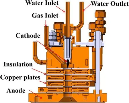
Figure 2.The schematic view of the cascaded arc source.
To investigate the plasma characteristics of the cathode arc source,an actively cooled planar target probe is designed to measure the ion flux.Figure 3 shows the configuration of the target system.The target consists of a tungsten collector plate, a molybdenum shield, a ceramics plate, four molybdenum bolts and a water-cooling copper holder.A DC tunable source is employed to measure the ion saturation current.The voltage of the resistor Usis recorded by a voltage meter.The tunable negative voltage from −200 to 0 V can be applied to the collector plate.A ceramic shield was installed to isolate plasma from the target.A hole with a diameter of 10 mm was designed in the center of the target and the ions can pass through the hole and bombard the collector.
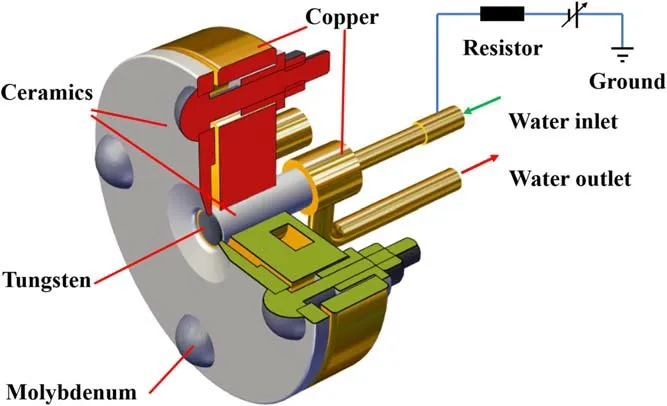
Figure 3.The schematic drawing of the actively cooled target to measure ion flux (zoomed in figure 1).
The ion flux to the target is calculated from the Bohm flux [15].When the adequate negative potential is applied,most of electrons are repelled and ions are accelerated to the probe.The ion flux can be calculated by the ion saturation current (Is0) [16]:
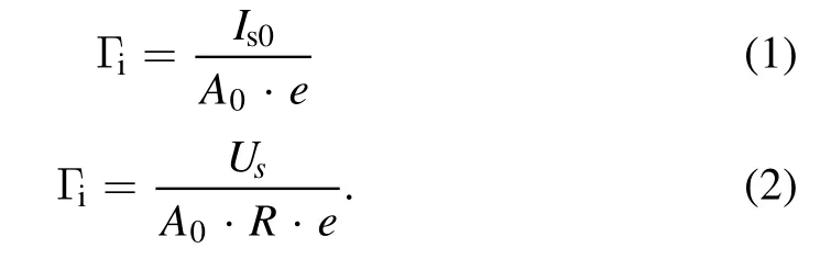
Here A0is the area of ion collection, e is elementary charge.The ion saturation current Is0can be acquired when the negative bias voltage to the target is high enough.Here A0is 7.85 × 10⁻⁵m2, R is 1 Ohm and e is 1.6 × 10⁻¹⁹C.A voltage of −45 V is applied to the tungsten collector,which is in the ion saturation regime [17].
3.Fluid conduction analysis
The fluid conduction in a vacuum is determined by fluid type in the chamber.The state of fluid can be distinguished by Knudsen coefficient (Kn):
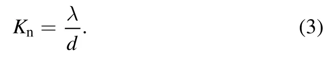
Hereλis the mean free path of gas molecule,d is the feature size of vacuum chamber.When Kn> 1,the fluid is molecular flow.There are some significant collision interactions between molecules and the wall of the chamber.When Kn< 0.01, the internal fiction of gas dominates, which is called continuous flow.Moreover, when 0.01 < Kn< 1,Knudsen flow is a transition stage between internal friction and gas molecules collision in the vacuum chamber.
The Knudsen coefficient is calculated by equation (3) and discharge pressure of 1–100 Pa is maintained in the compact vacuum system.As demonstrated in figure 4, both Knudsen flow and continuous flow exist in the operation range of pressure.Previous studies[7,18]show that high particle flux can be achieved in higher gas flow and discharge pressure, thereby continuous flow in the compact plasma source is analyzed.
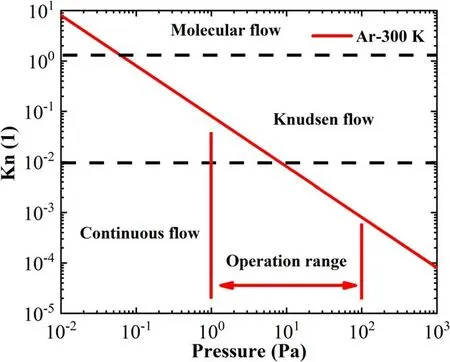
Figure 4.The range of operational gas pressure and Knudsen coefficient of this machine.
Using the theory of continuous flow model, the fluid conductance (Un,f) is described [19] by:
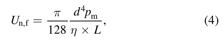
where d is the diameter of the vacuum chamber,pmis the mean pressure of the vacuum chamber,ŋis the coefficient of viscosity for argon, L is the equivalent length of the vacuum chamber.In the compact plasma source, fluid conduction at the position of the vacuum gauge is calculated to be 2210 L s−1.The effective pumping speed S of the compact chamber can be calculated by
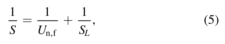
where SLis the nominal speed of roots pump.In this compact vacuum system,the effective pumping speed is calculated by equations (3)–(5).Calculation results show that 798 L s−1of the effective pump speed is obtained in the compact vacuum chamber.Finally, the operation pressure P is obtained from
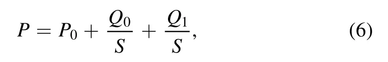
where P0is the limited vacuum of root pump,which is 0.1 Pa(P0≈ 0.1 Pa).Q0is the gas flow with unit of Pa L s−1.Q1is air leakage of the components and degassing from the material in vacuum system.Compared with the active gas fed in cascaded arc plasma source, Q1is neglected in the high gas flow experiment.
Figure 5 shows the comparison of experimental data and the calculated values of pressure versus gas flow.The experimental values are close to calculated ones.The pressure in the chamber increases linearly with the gas flow.The results reveal that the typical operating pressure of a cascaded arc plasma source[11,12]can be maintained with high gas fueling rate in our compact device design despite the poor fluid conduction.As mentioned above, the compact device is beneficial to improve the intensity of the peak magnetic field as well.
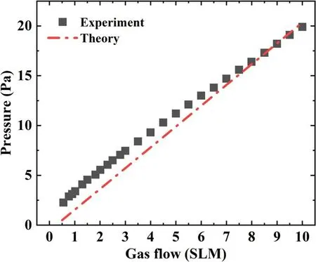
Figure 5.Comparison of the pressure results between experiment and theory calculation.
4.Experimental results
4.1.Steady-state plasma discharge
The steady-state plasma was operated under the discharge current of 150 A and gas flow of 10 SLM.The recorded ion flux is shown in figure 6(a).A high ion flux plasma larger than 0.5 × 1024m−2s−1can be achieved in our compact device by the conventional water-cooled solenoid coil and the continuous discharge time is up to 1 h.The total ion fluence is calculated to be ∼1.8 × 1027m−2, which is close to the ion fluence during the 400 s pulse in the ITER divertor.The operation magnetic field is shown in figure 6(b).The maximum magnetic field in plasma source is 0.28 T at the nozzle of the anode, and the peak magnetic field in the expanding chamber is 0.50 T at 0.20 m away from the anode nozzle.A magnetic field strength of 0.37 T is achieved in the target area.The solenoid currents of C1, and C2.C3 are 650 A, 300 A and 250 A, respectively.
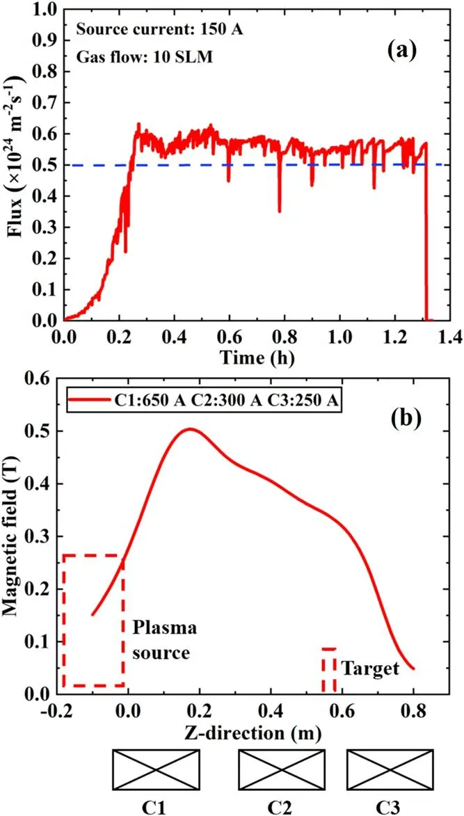
Figure 6.(a)The ion flux measurement for the 1 h plasma discharge and (b) axial magnetic field profiles.
The result of flux measurement suggests that there are some random undulations in the operation because of the turbulent flow type in the discharge channel at high gas flow.Simulation[20,21]results indicate that the fluid often transits from laminar within the discharge channel to turbulent at the target.The argon gas is ionized near the tungsten tip area and accelerated by the potential between the cathode and anode.Then the particles reach at anode region, under the drive of gradient pressure and thermal in the chamber.The plasma expands from the nozzle and goes through a stationary shock and then decreases in the turbulent flow module in the target area.The effects of turbulent flow in the compact plasma source will be studied in our future experiments.
4.2.The effect of the magnetic field profile
Figure 7 shows the relationship between the ion flux and the magnet currents of C1, C2.Figure 7(a) demonstrates that ion flux grows up from 1.40 × 10²³to 1.60 × 10²³m−2s−1with the operation current of C1 increasing from 400 to 750 A when the C2 and C3 are fixed at the current of 300 A.The corresponding peak magnetic field is 0.35–0.56 T along the Z-direction as shown in figure 8(a).However, figure 7(b)shows that the ion flux decreases from 2.30 × 10²³to 0.70 × 10²³m−2s−1with the operation current of C2 increasing from 100 to 700 A when C1 and C3 are set at 600 A and 300 A, respectively.The maximum and minimum operation magnetic fields are in the range of 0.28–0.60 T along the Z-direction in figure 8(b).Moreover, figure 7(c)shows that the ion flux measured in target decreases from 2.35 × 10²³to 0.85 × 10²³m−2s−1with the operation current of C3 increasing from 50 to 700 A when C1 and C2 are set at 600 A and 300 A, respectively.The maximum and minimum operation magnetic fields correspond to the range of 0.50–0.58 T in figure 8(c).There are three independent magnetic mirrors under the coils of C1,C2 and C3.C1 is the solenoid coil near the cascaded arc plasma source as shown in figure 1(b).Stronger magnetic field in the plasma source can reduce the attachment between the arc and copper plates and improve ionization efficiency.The magnetic field strength in the discharge channel significantly increased with the enhancement of C1 current.However, there is a magnetic mirror [22, 23] between the target and the front of the anode nozzle that seems to limit the transport of plasma from the plasma source to the target.Due to the mirror effects, the particle flux in the target area decreases with the increase of C2 and C3 currents when the operation current of C1 is fixed.
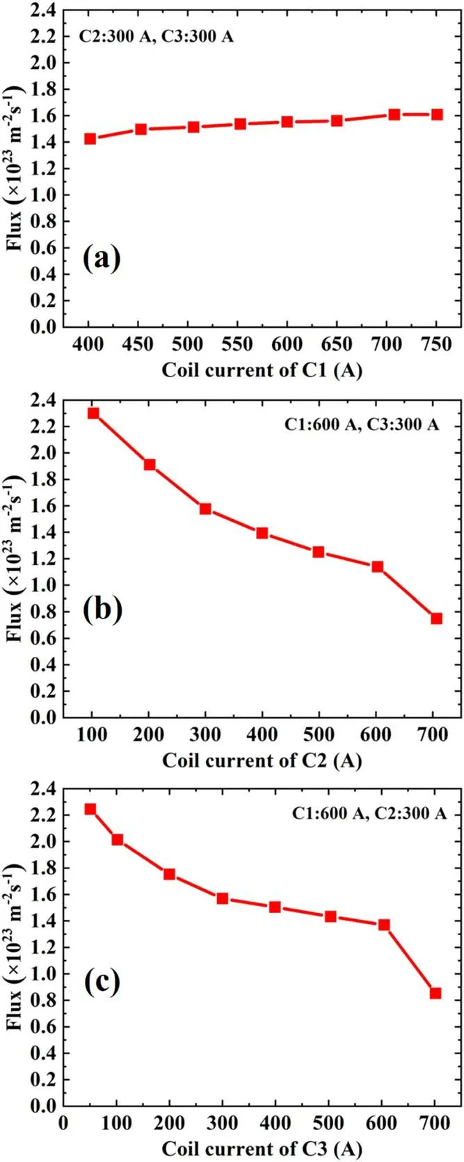
Figure 7.Measured ion flux as a function of coil current of (a) C1,(b) C2 and (c) C3.In each case, the currents of the other two coils are fixed.
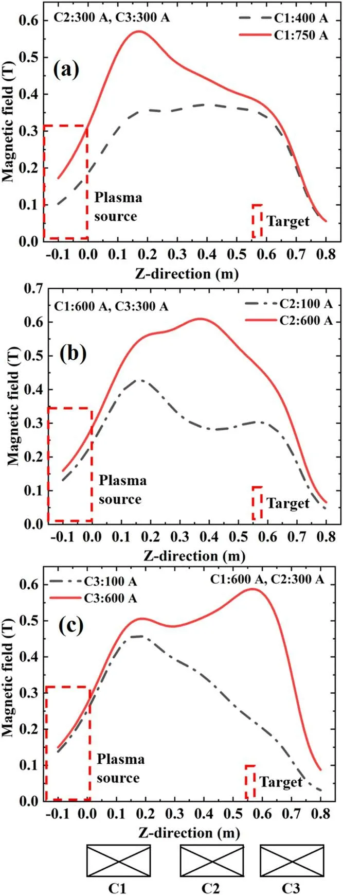
Figure 8.The maximum (red straight line) and minimum (black dotted line) operation magnetic field configurations when adjusting the current of(a)C1,(b)C2 and(c)C3.In each case,the currents of the other two coils are fixed.
4.3.The effects of gas flow and discharge current
The effects of gas flow and discharge current on the ion flux are studied.The argon ion flux at the target grows with the gas flow at a constant input arc current.The gas flow rate plays an important role in increasing the ion flux of argon plasma,which is consistent with the previous reports[15].As the argon gas flow grows,more neutral atoms are ionized and collected by the electric pole in the target.Moreover,the cold gas boundary layer is formed between the arc column and anode surface, and the cold gas boundary can hold the stability of the arc and decrease the anode erosion.It can be seen from figure 9 that ion flux increases rapidly as the arc current increases, which will be discussed in detail in the next paragraph.
The arc current dependence of ion flux was investigated as well.Figure 10 shows that argon ion flux grows with the arc current.Higher density plasma is produced at a higher arc current density [24].The possible reason is that the increase in applied current leads to the increase of electron kinetic energy.The power dissipated in the plasma column grows with the arc current.When the gas flow rate is fixed, cold atoms are heated and excited by the ohmic heating energy,which increases ion flux.
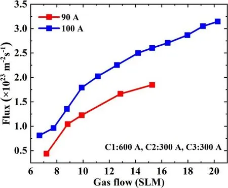
Figure 9.Ion flux as a function of gas flow for different discharge currents.The coils currents of C1,C2 and C3 are 600 A,300 A and 300 A, respectively.
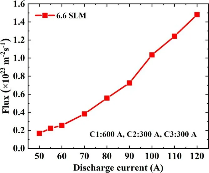
Figure 10.The ion flux as a function of cathode current.
5.Conclusions
A compact cascaded arc plasma source for PWI study is developed at the Institute of Plasma Physics,Chinese Academy of Sciences.With a relatively low fluid conductance,high flux steady-state experiments are performed successfully.The magnetic field configuration has significant effects on target flux.Experimental results indicate that a uniform magnetic field is not beneficial to achieving high flux in cascaded arc plasma sources.On the contrary, ion flux of target is growing with the augment of the magnetic field in the source area.The gradients of the magnetic field in the axial direction are also conductive to acquire high flux plasma in the target area,which suggests that the magnetic field mirror effects play an important role in axial plasma transport.Moreover, higher ion flux can be achieved in a higher arc current and a higher gas flow rate.The performance of the device can be further improved.It has been found that the ion flux was an undulant variation in the steady-state operation of cascaded arc plasma, suggesting that the flow type in expand chamber plays an important role in plasma characteristics at the target area,which warrants further investigation in this new device.
Acknowledgments
This work was supported by Comprehensive Research Facility for Fusion Technology Program of China(No.2018-000052-73-01001228) and the Youth Innovation Promotion Association CAS (No.2018484).The authors would like to thank Dr T W Morgan and Dr H J N van Eck for their suggestions to our facility.
杂志排行
Plasma Science and Technology的其它文章
- Spatial and temporal evolution of electromagnetic pulses generated at Shenguang-II series laser facilities
- Numerical study on the loss of fast ions produced by minority ion cyclotron resonance heating in EAST
- Machine learning of turbulent transport in fusion plasmas with neural network
- Observation of coherent mode induced by a molybdenum dust on EAST
- Investigation of stimulated Raman scattering in longitudinal magnetized plasma by theory and kinetic simulation
- The influence of magnetic field on the beam quality of relativistic electron beam long-range propagation in near-Earth environment