Simulations on the multi-shell target ignition driven by radiation pulse in Z-pinch dynamic hohlraum*
2021-11-23ShiJiaChen陈诗佳YanYunMa马燕云FuYuanWu吴福源XiaoHuYang杨晓虎YunYuan袁赟YeCui崔野andRafaelRamis
Shi-Jia Chen(陈诗佳) Yan-Yun Ma(马燕云) Fu-Yuan Wu(吴福源) Xiao-Hu Yang(杨晓虎)Yun Yuan(袁赟) Ye Cui(崔野) and Rafael Ramis
1Department of Physics,National University of Defense Technology,Changsha 410073,China
2IFSA Collaborative Innovation Center,Shanghai Jiao Tong University,Shanghai 200240,China
3College of Advanced Interdisciplinary Studies,National University of Defense Technology,Changsha 410073,China
4Laboratory of Laser Plasmas School of Physics and Astronomy,Shanghai Jiao Tong University,Shanghai 200240,China
5E.T.S.I.Aerona´utica y del Espacio,Universidad Polite´cnica de Madrid,Spain
Keywords: Z-pinch,dynamic hohlraum,radiation pulse,volumetric ignition
1. Introduction
Radiation pulse shaping is important for inertial confinement fusion driven by lasers,[1-3]ion beams[4]or Zpinches.[5-7]For a hot-spot central ignition target, a proper pulse shape that can generate three or four shocks with precise timing and amplitudes is required to ignite the fuel with minimal energy.[8]For volumetric ignition targets,such as doubleshell targets[9-13]or multi-shell targets,[14-18]although much simpler pulse can be used,an appropriate shape is still needed when other considerations are taken into account. For example, Amendt[10]recommended an x-ray pulse with radiation temperature nearly constant in time to reduce the plasmamediated laser backscatter and minimize the fuel mixing in the double-shell target implosion on National Ignition Facility.
In principle, either central ignition targets or volumetric ignition targets can be used for Z-pinch dynamic hohlraum driven fusion, since plenty of radiation energy is available.In 2007,Rochau[5]observed that up to 3.5×10¹¹deuteriumdeuterium(DD)thermonuclear neutrons could be produced by using a central ignition target on the 20-MA Z machine located at Sandia National Laboratories without special pulse shaping technology. In the same year and much earlier,Vessey[19]and Hammer[20]demonstrated the radiation pulse shape required by central ignition targets could be generated through a double-ended hohlraum. In 2016, Cobble[11]described that a double-shell target could be ignited by a double-ended hohlraum via volumetric ignition.However,the radiation temperature obtained by a double-ended hohlraum is much lower than that achieved by a dynamic hohlraum on the same Zpinch facility.For example,the radiation temperature obtained by a double-ended hohlraum is just about 90 eV[21]on Z machine, which appears to be sensitive to the hohlraum sizes,while a radiation temperature of 215 eV[22]has been measured by using a dynamic hohlraum. So,it would be meaningful to explore the scheme of volumetric ignition driven by the radiation pulse inside a Z-pinch dynamic hohlraum,which can well utilize the characteristics of the Z-pinch dynamic hohlraum: it is easy to generate plenty of radiation energy but difficult to modulate the pulse shape.
In 2014, Peng[23]proposed the concept of a Z-pinch dynamic hohlraum-driven multi-shell target ignition, but nothing about the target structure and parameters were described.For the first time, we present the simulations of a multi-shell target ignition driven by the radiation pulse inside a Z-pinch dynamic hohlraum. A new hohlraum configuration is used to generate the required radiation pulse. In the configuration, a single metal liner is employed. A plastic foam covered with a metallic foam is adopted to prevent the low-density foam from being ablated by x-rays before the collision of liner and converter. The target is designed on the bases of the doubleshell target proposed by Cobble[11]for Z-pinch driven fusion and the multi-shell target suggested by Molvig for laser driven fusion. Noticing that most next-generation Z-pinch machines have a peak drive current of 40 MA-70 MA,[23,24]the drive current is set asI(t)=50(MA)sin2(πt(ns)/610). The study of the important multidimensional effects such as magneto-Rayleigh-Taylor MRT instability remain outside the scope of these simulations. Even though these multi-dimensional effects have turned out to be a key issue in common Z-pinch dynamic hohlraum experiments. One-dimensional(1D)simulations are useful for quick orientation when changing designs and drive parameters.
The rest of the paper is organized as following. Section 2 outlines the method. Section 3 and Section 4 describe the results of the Z-pinch dynamic hohlraum implosion, and the multi-shell target ignition by using the 1D code MULTIIFE.[25,26]Finally,a summary is given.
2. Method
The concept of Z-pinch dynamic hohlraum driven fusion and the schematic of the multi-shell target investigated in this work are illustrated in Fig. 1. The hohlraum is composed of a Z-pinch liner, a high-Z metallic foam, a low-Z plastic foam, and electrodes. The multi-shell target is composed of a deuterium-tritium (DT) fuel, a gold pusher, a gas buffer, a copper driver,a gas buffer and a beryllium ablator.
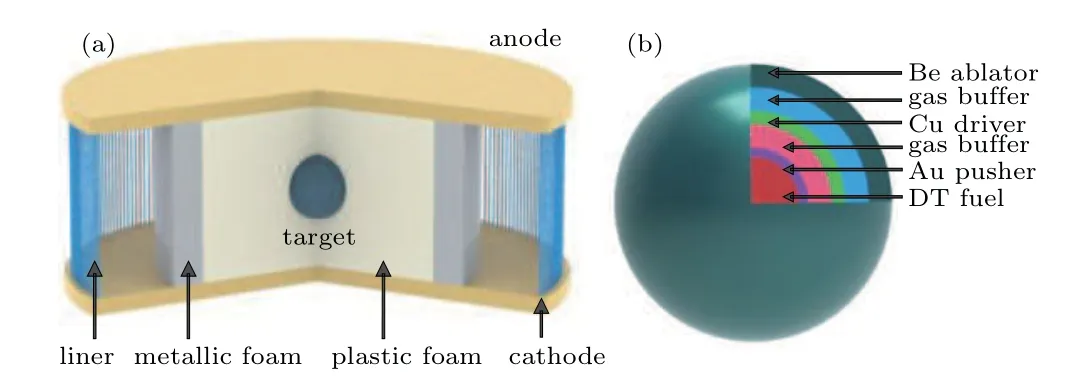
Fig.1. The schematics of Z-pinch dynamic hohlraum driven fusion(a)and the multi-shell target(b).
As shown in our previous two-dimensional(2D)simulations for an 8-MA driver[27]and the following results for a 50-MA driver,the foam convertor is able to convert the cylindrical imploding kinetic energy into radiation energy with good uniformity in the hohlraum. It is reasonable to decouple the calculation of hohlraum implosion and target implosion when a two-dimensional code with accurate physical models are not yet available and efficient simulations are expected. In the next sections, we first study the hohlraum implosion to get a proper radiation pulse in cylindrical coordinates,then investigate the multi-shell target ignition driven by the obtained radiation pulse in spherical coordinates. Margins in target implosion time and energy gain are designed to compensate the potential overestimation caused by the decoupled calculations.
The code MULTI-IFE is employed to perform the simulations. MULTI-IFE is a 1D radiation magneto-hydrodynamic program with separate electron and ion components. Radiation transport is solved by using the forward-reverse method for multi-group x-rays. A DT fusion package with alpha particle diffusion model is also integrated. The equations of state and opacity are taken from the model of MPQEOS[28]and SNOP[29]respectively. And the 1D equations can be expressed as follows:
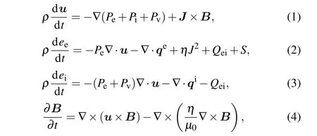
where equation (1) is the momentum conservation equation,equations (2) and (3) are the energy conservation equations for electrons and ions respectively, equation (4) is the magnetic field evolution equation.Most quantities in the equations follow the usual convection.ρis the plasma density,uis the plasma velocity.Pe,Pi,Pvare the electron, ion, and artificial viscosity pressures.Jis current density,Bis magnetic field strength.eeis electron specific energy,qeandqiare the thermal fluxes carried by electrons and ions, respectively.Qeiis the energy exchanging power between electrons and ions,ηis resistivity,Sis source term,such as energy deposition from laser or radiation.eiis ion specific energy.µ0is permeability of vacuum.
3. Simulation on dynamic hohlraums
To demonstrate that a metallic foam is necessary for the generation of required radiation pulse,two types of hohlraums are investigated as shown in Fig.2. The first type(type A)is a traditional one where the converter is made of plastic foam with uniform density. The second type(type B)is the one designed to produce a radiation pulse suitable for volumetric ignition targets,where the foam consists of a low-Z plastic foam and a high-Z metallic foam. The low-density plastic foam is designed to support the fusion target and make the x-ray radiation transport fast. The high-Z metallic foam is designed to prevent the plastic foam from being ablated by the imploding liner plasma, to convert the kinetic energy into radiation energy as early as possible, and to provide additional x-ray confinement ability as part of the hohlraum wall.
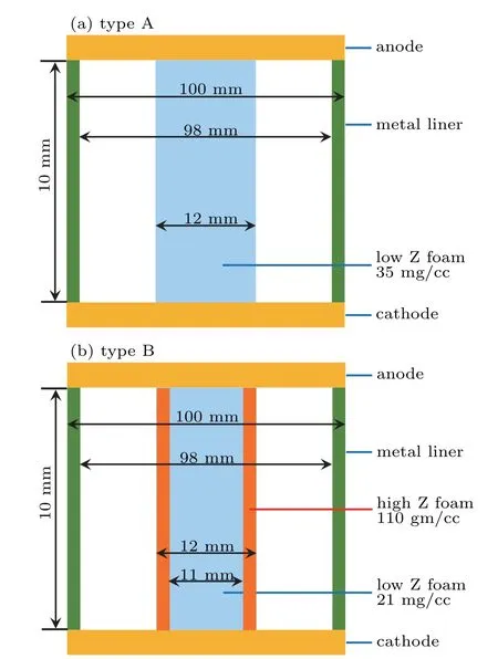
Fig. 2. Schematic diagram of two kinds of hohlraum investigated in this work.
The initiation of the Z-pinch liner can be a complicated process. If the liner is made of an extremely thin metal shell or a narrow-gap ribbon array,the precursor plasma may be restrained effectively,[30]which leads the liner to be imploded in shell model. If the liner is made of wire array, the liner may implode in a snow-plow way.[31]In this case, the wire array first undergoes a long ablation phase,then the wire core mass implodes through the ablated plasma inside the wire array.Since the wire initiation process cannot be simulated completely by our hydrodynamics code, we start the calculation with approximations which are commonly adopted in Z-pinch simulation community,[32,33]in which some of the liner mass is uniformly distributed inside the liner shell with zero velocity.
Based on above discussion and previous work,[34]the drive current is set asI(t)=50(MA)sin2(πt(ns)/610) with a 10%-90%rise time of 180 ns,the hohlraum height is set as 10 mm, the tungsten liner is modelled as a plasma shell with a radius of 50 mm,a thickness of 1 mm,a mass of 30 mg/cm,and a temperature of 1 eV. The driven energy is high enough due to the rise time of 180 ns and benefits to fusion.For type-A hohlraum,the CH foam has a density of 35 mg/cc and a radius of 6 mm. For type-B hohlraum,the CH foam has a density of 21 mg/cc and a radius of 5.5 mm,the metallic tungsten foam has a density of 110 mg/cc and a thickness of 0.5 mm.Both the plastic foam and metallic foam have a temperature of 0.1 eV.In this way,both kinds of hohlraum have a mass of 40 mg/cm for the foam. The optimized liner radius is set as 50 mm to provide enough implosion velocity. However,the liner radius is limited by the MRT instability.The instability developments greatly depend on the initial radius of the liner,which may results in a significant decrease in the radiation temperature in the hohlraum. The convergence ratio of the liner at collision time is designed as 8.3. As the simulations here are based on 1D model,the tungsten liner implosion is an ideal assumption.The study of reducing or even avoid MRT instabilities will be discussed in the future. For example, a relatively small convergence ratio of the liner is helpful in mitigating the growth of MRT instability.[35-37]The convergence will be discussed in detail in 2D simulations.
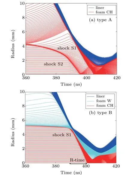
Fig.3. The implosion diagram for the two kinds of hohlraum.
The implosion diagram of two types of hohlraums are plotted in Fig. 3. It is shown that they have significantly different behaviors. For type-A hohlraum,there are two shocks.One(shock S1)is launched by the collision of liner and converter as desired, the other (shock S2) is driven by the radiation ablation,which is emitted by the hot imploding liner with radiation temperature over 50 eV. Ablation shock waves are normally present under a high driven current. While the current rise time is reduced,the impact of the ablation shock wave will be significantly reduced. For type-B hohlraum, although the tungsten foam is also ablated by the imploding plasma,the plastic foam is well protected. Only a single shock with a velocity about 45.35 cm/µs is launched due to the collision of Z-pinch liner and foam converter. This velocity is close to the maximum implosion velocity(50.3 cm/µs)of liner but larger than that of fusion targets(20 cm/µs-40 cm/µs).
A small rectangle ‘R-time’ is marked explicitly in Fig.3(b)indicating the region of radiation time covered later by Fig.7(b).It emphasizes the fact that although a shock wave is advancing fast towards the axis,destroying everything in its path, the radiation driven implosion is faster and finally ignition occurs with some margin before the wave arrives. On the contrary,in case(a),the first shock wave arrives prematurely,probably destroying the capsule.

Fig.4. The profiles of radiation temperature and pressure at 388 ns.
The profiles of radiation temperature and pressure at the collision time (t= 388 ns) are displayed in Fig. 4. When the converter is made of uniform plastic foam as in type-A hohlraum,an undesired weak thermal wave and the shock S2 launched by the radiation ablation can be observed. The target will be preheated by the weak thermal wave and compressed cylindrically by the shock S2 before ignition. The pressure at the front of shock S2 can achieve as high as 24 Mbar(1 bar=105Pa). However,when the plastic foam is covered with a metallic foam as the situation of type-B hohlraum,the preheat of plastic foam is well suppressed, and the shock S2 driven by the radiation ablation is eliminated. Xiao[38]proposed that the expansion of the ablated plasma will weaken the shock propagation and decrease its velocity with a critical hohlraum radiation temperature. The effects of the shock propagation transferring into the ablator plasma will be considered in future hohlraum design.
The tungsten layer is relatively thick owing to a large driven current. Thus the tungsten layer has good thermal insulation effects. Besides, the equations of state and opacity are different from the simulations of the Z machine. Both results in the relatively high radiation temperature in the tungsten layer.The radiation temperature is an ideal situation without multidimensional effects. The MRT instabilities remain outside the scope of 1D code. Even though the development of MRT instability in the Z-pinch implosion is a key issue,and results in relatively strong radiation missing. One dimensional simulations give qualitative results and are useful for quick orientation when changing designs and drive parameters. In the next section, the radiation pulse on the pole between 389 ns and 400 ns will be employed to drive a multi-shell target. This radiation pulse shape obtained by type-B hohlraum also differs from that observed on Z machine previously (Fig. 3 of Ref.[39]),where the plastic foam is not covered with a metallic foam and the radiation temperature rises slowly until the shock arrives at the foam center. A sharp rise in the radiation pulse is favorable for Z-pinch driven fusion,because the target can be imploded as early as possible when the shock in the foam is still far away from the target.
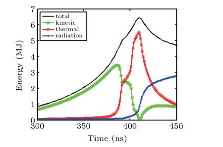
Fig.5. The hohlraum energetics for 50-MA driver.
The hohlraum energetics of type-B is plotted in Fig. 5.The total energy is the sum of kinetic energy, thermal energy and radiation energy lost on the hohlraum surface. It is shown that kinetic energy carries most of the total energy until the liner plasma starts to collide with the foam converter, with a ratio ofEkinetic/Etotal=3.46 MJ/4.37 MJ at 386 ns. During the collision of liner and foam converter, the thermal energy increases rapidly due to the conversion of kinetic energy and the compression work applied by magnetic field outside the liner. A favorable result from this hohlraum energetics is that the radiation loss is almost negligible during the collision of liner and converter because of the good x-ray confinement ability of the tungsten plasma. The radiation loss keeps relatively small (<0.24 MJ) until the shock arrives at the foam center at 401 ns. The radiation loss only increases dramatically after the shock reaches the foam center and the plasma starts to stagnate.
4. Implosion dynamics of the multi-shell target
In this section, we present the implosion dynamics of a multi-shell target driven by the hohlraum radiation pulse obtained above. The schematic and implosion diagrams of the target are plotted in Fig.6. The target implosion timet=0 ns corresponds to the hohlraum implosion timet= 389 ns in Fig.5. The target is adapted from that proposed by Molvig[14]for laser directly drive fusion, which is composed of a beryllium ablator, a copper driver, a gold pusher, a deuteriumtritium (DT) fuel, and a DT gas buffer. The density of different materials is set asρBe=1.860 g/cc,ρCu=8.938 g/cc,ρAu=19.292 g/cc,ρDT=0.173 g/cc,andρbuffer=0.038 g/cc.The DT fuel is in the state of cryogenic liquid (33 K) with a total mass of 36.7µg.
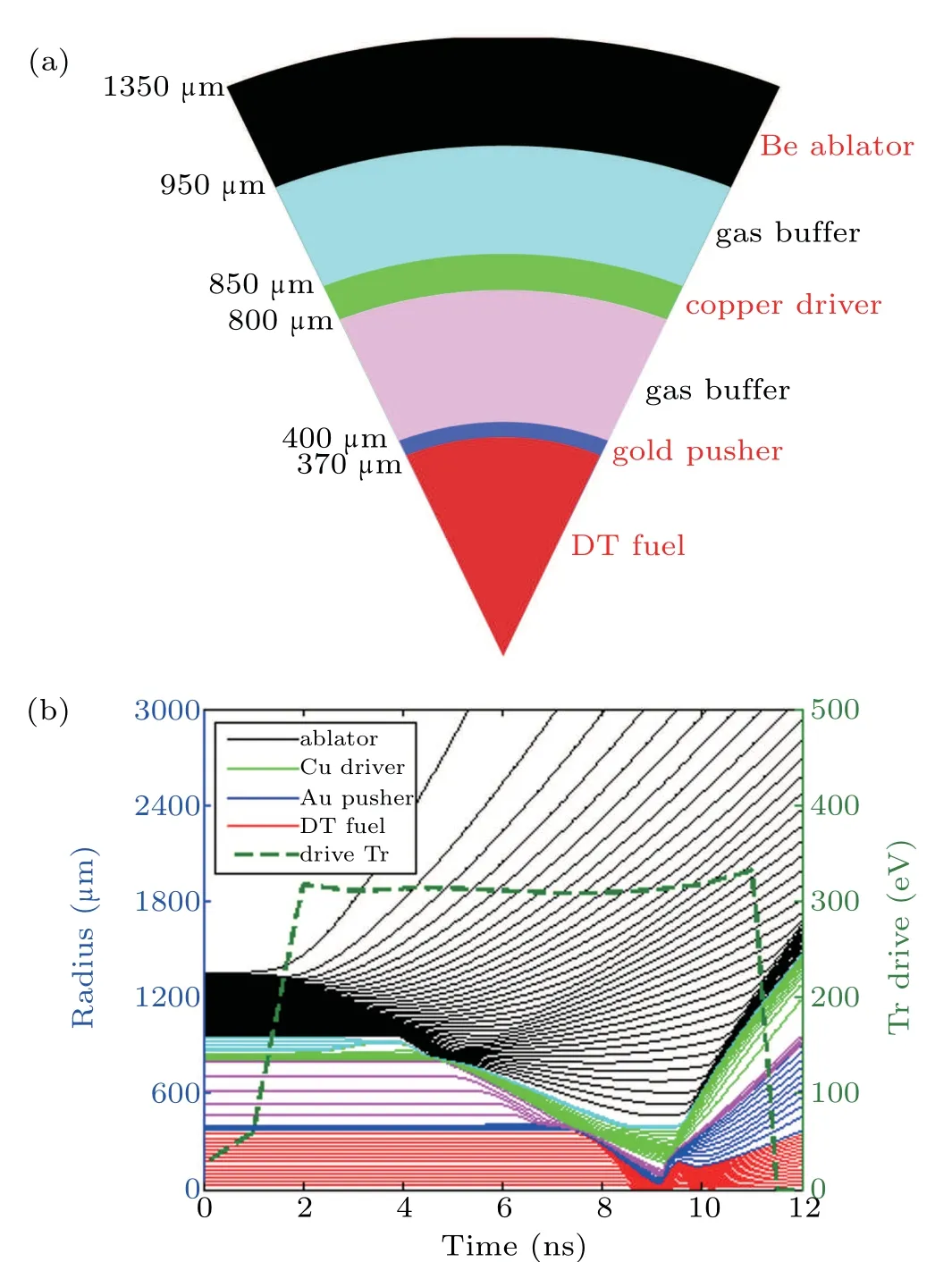
Fig.6. Schematic and implosion diagram of the multi-shell target.
The target is optimized with thickness and density selected carefully. On the one hand, the finally ignition should occur before the shock wave arriving. On the other hand, the instability can be partly alleviated by a relatively thick target.The beryllium ablator is designed to convert hohlraum radiation energy into spherical imploding kinetic energy. The copper driver is utilized to shield the incoming energetical x-rays in the radiation field with a radiation temperature over 300 eV.The gold pusher is used to reduce the radiation loss in DT fuel and provide additional inertia to delay the fuel disassembly,so that a volumetric ignition can be expected.
Compared to the situation of laser directly drive fusion,there are some special conditions to be kept in mind when one designs a multi-shell target for Z-pinch dynamic hohlraum.The first is that the target has to ignite before it is destroyed by the cylindrical shock inside the hohlraum. The second is that the drive radiation field always exists until the hohlraum is disassembled. Thus,compared to the target used in laser directly drive fusion, a target with much smaller size (r=1.35 mm)but much thicker ablator(400µm)is adopted here. As shown in Fig.7,the DT fuel is able to stagnate at 9.178 ns,which is about 3 ns earlier before the shock reaches the foam center. At the stagnation time of 9.178 ns,the radius of copper driver is 0.4 mm while the cylindrical shock(S1)in the hohlraum is at the position of 1.55 mm as shown in Fig. 3(b). This implies the cylindrical shock may have little effect on the target implosion. As the simulations here are based on 1D model, much more details about the match between the hohlraum and target will be discussed in the future 2D simulations.
The driver velocity,pusher velocity,and normalized neutron generation rate are illustrated in Fig. 7(a). It is shown that the speed of copper driver changes from−16.57 cm/µs to +6.48 cm/µs during the collision with gold pusher, while the speed of gold pusher changes from +2.46 cm/µs to−20.22 cm/µs. Here,the sign‘-’means the direction toward to the center,while‘+’presents the direction outward. And a small rectangle‘C-time’is marked explicitly in Fig.8(a)indicating the region of collision time. The multiplication factor between copper driver and gold pusher is about 1.22.The neutron yield starts to burst at the time of 9.0 ns and lasts about 300 ps. The velocities of gold pusher and copper driver keep negative when the neutron generation rate reaches the peak value at 9.178 ns, which indicates the fusion occurs well upstream of stagnation.
Hydrodynamic instability is of great importance for all inertial confinement fusion implosions. Since upstream ignition and thick shells with short acceleration distances are designed for the target, the effects of hydrodynamic instability may not be catastrophic. For example,owing to the upstream ignition design,the growth of Richmeyer-Meshkov(RM)instability and Rayleigh-Taylor(RT)instability will be negligible because there is no continuous deceleration until the target ignites. The other source of RT instability locates at the outer surfaces of the gold pusher,copper driver and beryllium ablator during the acceleration process,where the shells are accelerated by lighter fluid. According to the assessment method used by Molvig,the gold pusher owns the biggest RT instability bubble penetration fraction with a value about 0.8, which indicates the shell would keep intact during the acceleration.
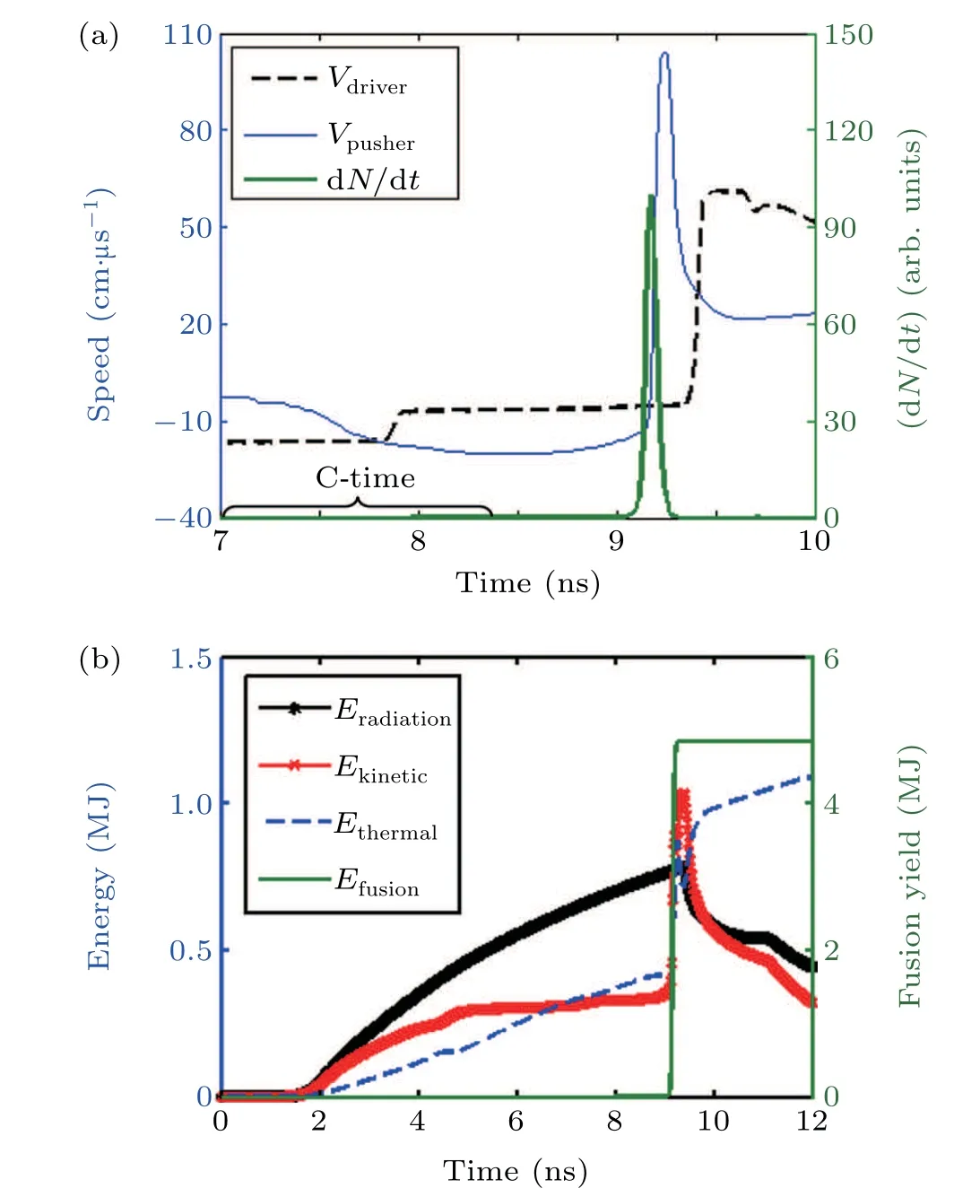
Fig.7. Time evolution of driver velocity,pusher velocity,neutron generation rate(a),and the time evolution of different energies(b).
The time evolution of the different energies are shown in Fig. 7(b). TheEradiationrepresents the net radiation energy absorbed by the target from the radiation field. TheEfusionmeans the energy generated by the DT fusion. It is shown that the ratio between fusion energy (4.83 MJ) and absorbed radiation energy (780 kJ) isEfusion/Eradiation=6.19 at the time of 9.26 ns,which implies the ignition has been achieved with sufficient margin. The corresponding burn efficiency of the fuel is about 20%. Note that the energy absorbed by the target from the radiation field will reduce the black hohlraum radiation temperature in the hohlraum-target coupling condition.This will be considered in further target design in the integrated simulation. The energy generated by fusion depends on the DT fuel density, a higher energy gain can be achieved if the liquid DT fuel is replaced by DT ice. The absorbed radiation energy depends on the target size,more radiation energy would be required if the target is larger. Before ignition,it is also observed that the absorbed radiation energy is converted to thermal energy and kinetic energy with almost equal fraction. Once the target ignites, the high pressure and high temperature inside the target make the target expand and emit more radiation energy than that absorbed from the drive radiation field.
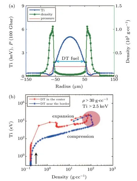
Fig. 8. Profile of ion temperature, density, and pressure at 9.0 ns (a) and trajectories of DT fuel in temperature-density space before 9.3 ns. A pink ellipse is plotted to indicate the statuses with ρ >30 g/cc and Ti>2.5 keV(b).
The profiles of ion temperature, density and pressure at time 9.0 ns are plotted in Fig. 8(a). It is shown that the DT fuel has been compressed from 370µm to 50µm,with a convergence ratio about 7.4. Most of the DT fuel has an ion temperature over 2.5 keV and a density larger than 30 g/cc,a typical fusion status due to the radiation trapping of a gold pusher.Because there always exists a heat flow on the fuel surface and the shock intensity becomes stronger as it converges to the center,a temperature gradient is generated unavoidably in the DT fuel. This temperature gradient results in a density gradient in the fuel to form an isobaric ignition structure. The trajectories of the DT fuel in the center and near the border before 9.3 ns are plotted in the temperature-density space in Fig. 8(b). It is observed that both the DT fuel in the center and near the border are mainly compressed adiabatically,with a constant slope about 2/3 during the compression and expansion process. Because of the temperature gradients in the fuel,the trajectory of the DT fuel near the border is lower than that of the DT fuel in the center. However, the differences in fuel status are not so significant that the DT fuel in the center and near the border reach the fusion conditions almost at the same time. The plasma statuses with density larger than 30 g/cc and ion temperature larger than 2.5 keV are indicated with a pink ellipse in Fig.8(b). These trajectories of DT fuel are qualitatively different from that for a hot-spot central ignition target(Fig.3.12 of Ref.[2]),where the DT fuel is initially composed of DT gas and DT ice, the DT gas is strongly heated by the shock and ignites at about 4.5 keV.From the above analyses,one can identify that the target has been ignited via volumetric ignition rather than central hot-spot ignition.
5. Summary
First simulations on the multi-shell target ignition driven by the radiation field in Z-pinch dynamic hohlraum is presented. Compared to traditional hot-spot central ignition scheme, this volumetric ignition scheme can well match the characteristics of Z-pinch dynamic hohlraum:it is easy to generate plenty of radiation energy but difficult to modulate the radiation pulse shape. A new type of hohlraum composed of a metal liner,a plastic foam,and a metallic foam is proposed to produce the required radiation pulse. A small multi-shell target with a thick ablator is employed to meet the special environment of Z-pinch dynamic hohlraum.
For a Z-pinch facility with a peak drive current of 50 MA and a rise time of 180 ns,1D simulations suggest that a radiation pulse with a nearly constant temperature(~310 eV)and lasts about 9 ns can be created. Driven by this radiation pulse,a multi-shell target absorbing 780-kJ radiation energy is able to achieve volumetric ignition with an energy gain (G) about 6.19, whereGis the ratio of the yield to the absorbed radiation. These encouraging results can provide a good support for the construction of next generation Z-pinch facility with a peak current of 50 MA in China or other places. One dimensional simulations are useful for quick orientation when changing designs and drive parameters. But the multidimensional effects remain outside the scope of this code. In the future, two-dimensional calculations would be conducted to better understand the effects of hydrodynamic instability on the hohlraum and target implosion performance.
Acknowledgment
The authors would like to express their thanks to Jing-Long Jiao,Guo-Bo Zhang,Bo Zeng and Ze Li for many helpful discussions during the development of this work.
杂志排行

Chinese Physics B的其它文章
- Numerical investigation on threading dislocation bending with InAs/GaAs quantum dots*
- Connes distance of 2D harmonic oscillators in quantum phase space*
- Effect of external electric field on the terahertz transmission characteristics of electrolyte solutions*
- Classical-field description of Bose-Einstein condensation of parallel light in a nonlinear optical cavity*
- Dense coding capacity in correlated noisy channels with weak measurement*
- Probability density and oscillating period of magnetopolaron in parabolic quantum dot in the presence of Rashba effect and temperature*