Numerical simulation of acoustic field under mechanical stirring∗
2021-10-28JinHeLiu刘金河ZhuangZhiShen沈壮志andShuYuLin林书玉
Jin-He Liu(刘金河), Zhuang-Zhi Shen(沈壮志), and Shu-Yu Lin(林书玉)
School of Physics and Information Technology,Shaanxi Normal University,Shaanxi Key Laboratory of Ultrasonics,Xi’an 710119,China
Keywords: ultrasonic degradation,acoustic field,finite element method,flow field
1. Introduction
With the economic development and population increase,water pollution particularly caused by organic solutions generated by chemical industries is becoming an increasingly global issue. Therefore, identifying an efficient, economical, and green way to degrade organic matter is essential to human health and the world’s economic and social development. Advanced oxidation processes (AOPs) have been extensively researched for the degradation of organic pollutants from wastewater. Compared to traditional water treatment technologies, AOPs have a higher rate of degradation of organic pollutants,and induce no secondary pollution. They include a series of powerful technologies: photo-catalysis,Fenton reaction, and photo-Fenton, etc. The basic principle of AOPs is a process in which highly oxidizing free radicals(such as OH•)are produced by a catalyst,light,sound,and electricity,which degrade organic pollutants into harmless water and carbon dioxide.[1–3]Among all of the AOPs, the ultrasound treatment is the one that attracted growing attention in the field of degradation research.[4,5]
The effects of sonication are mainly induced by cavitation bubbles. Acoustic cavitation is divided into stable cavitation and transient cavitation based on the duration of the bubbles’growth periods. When a bubble is in a stable cavitation,it pulsates with the periodic expansion and compression derived from acoustic waves, during which the bubble does not collapse. When in a transient cavitation, a cavitation bubble begins to expand under the action of the ultrasound wave,before rapidly collapsing. The collapse of bubbles results in an area of high temperature and pressure and is accompanied by a shock wave, which in turn produces highly active hydroxyl radicals in water.[6,7]
Therefore,the acoustic field distribution and the acoustic intensity in cleaning tanks are the two most important parameters in the degradation of organic pollutants,as so many related studies have reported.[8–15]Pugin[8]described how standing waves cause an inhomogeneous acoustic distribution.Klimaet al.[11]showed that acoustic intensity increases through optimisation of the geometry of sonochemical reactors. They concluded that an optimum reactor size can greatly improve the local ultrasonic intensity. Zhaiet al.[14]established that the 2D and 3D ultrasounds enhance the sound pressure level and the mean acoustic energy density. Their results indicated that compared with 1D ultrasound,2D and 3D ultrasounds can,not only significantly improve the sound pressure level and sound energy density, but also enlarge the cavitation volume of liquid. Besides,Zhanget al.[15]studied the influence of acoustic directions on acoustic field characteristics. Simulation results from experimental tests showed that adjusting the direction of the acoustic wave can significantly improve the acoustic intensity and the acoustic field distribution. However, the optimization of acoustic field distribution through the interaction of flow field and sound field is rarely stated.
Yasudaet al.[16]reported that stirring solutions can increase the rate of sonochemical reaction,but there is no analysis to explain this result. Therefore, in this paper, acoustic field distribution and flow field with agitation will be explored through a numerical simulation. Then, the corresponding experiments will be implemented to verify the simulation.
2. Methodology
2.1. Simulation method
In order to obtain the correct distribution of the fluidic and acoustic fields, numerical simulations have been carried out. The flow field is calculated by the continuity equation
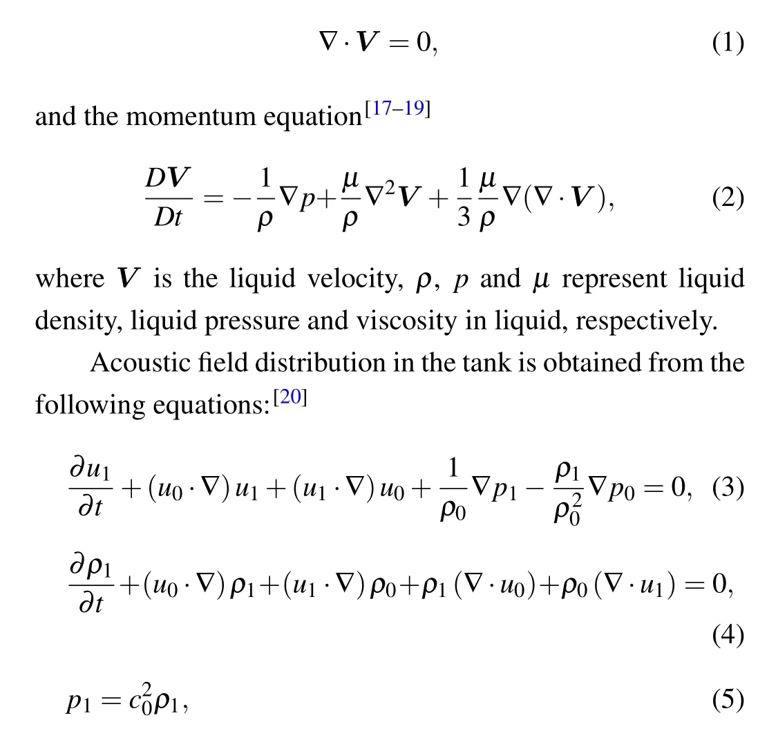
whereu0,ρ0, andp0stand for liquid velocity, liquid density and pressure,respectively,which are obtained by Eqs.(1)and(2).ρ1is the incremental liquid density due to the acoustic wave, andu1, andp1are the incremental liquid velocity and pressure, namely, the particle velocity and the acoustic pressure,respectively.
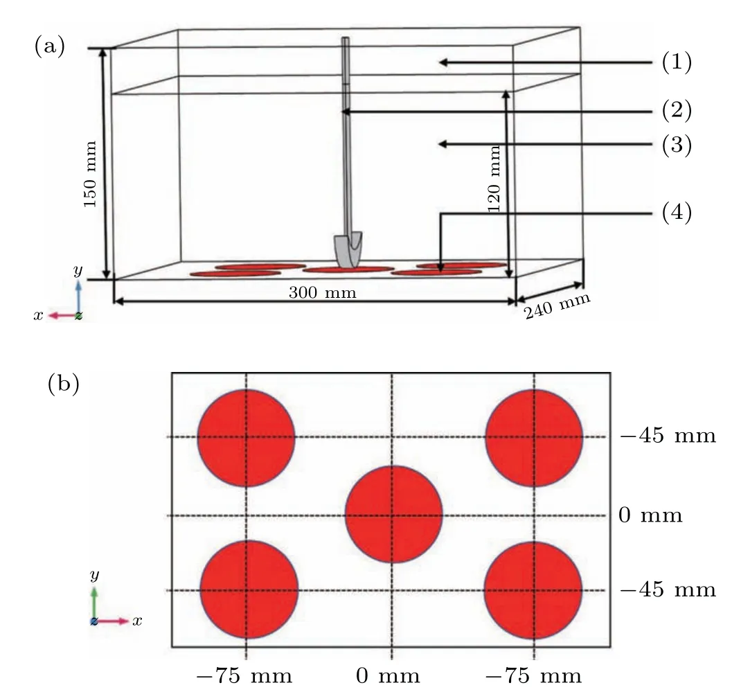
Fig.1. Schematic diagram of the numerical model: (a)the overall configuration: (1)air,(2)agitator,(3)water,(4)transductor;and(b)the position of five transducers.
A schematic drawing used for simulation is depicted in Fig. 1, which consists of rectangular ultrasonic tank with dimensions of 300 mm×240 mm×150 mm and an agitator.Five transducers(40 kHz,300 W)with a radius of 34 mm are attached at the bottom of the tank. The acoustic speed in air and water are 340 m/s and 1500 m/s,respectively.The simulation software used in this paper is COMSOL Multiphysics 5.4.In the laminar flow module of the software,the rotation of the agitator is equivalent to a boundary condition. The boundary range is the shape of the agitator,and the boundary speed is the rotational speed. Then Eqs.(1)and(2)are used to obtain the velocity,pressure,and density in the cleaning tank,and eventually these parameters are substituted into Eqs.(3)–(5)in the convective wave equation(cwe)module to obtain the acoustic field distribution.
2.2. Experiment
In order to explore the influence of vortex on the degradation rate of solution and verify the simulation results, the degradation experiment was performed. The experimental equipment mainly consisted of a numerical show precise power mixer with a power of 100 W (JJ-1A, Jiangsu Changzhou Ronghua instrument manufacture Co.Ltd.,China)and a cleaning tank (SB-5200DTD, Ningbo Xinyi ultrasonic equipment Co. Ltd., China) whose geometric dimensions and acoustic parameters are consistent with that of the simulation model. 10 mg of methylene blue (analytical grade,purity≥98.5%,Tianjin Zhiyuan Chemical Reagent Co. Ltd,China)was dissolved in 6 L of the twice-distilled water. The solution was measured using a UV visible spectrophotometer(UV-2400) that can detect the wavelength range of 190 nm–1100 nm.
The temperature of the solution was controlled at 24°C by circulating water and the agitator was placed in the center of cleaning tank’s bottom. The appropriate amount of solution was taken into the cuvette, then the cuvette containing the solution was placed into the spectrophotometer for measurement. The absorbance of the solution was recorded every 30 minutes using a spectrophotometer.
3. Results and discussion
The first simulation performed was the acoustic field distribution with and without the agitation,and then different stirring speeds were tested from low to high: 300 rpm,600 rpm,and 2000 rpm.In order to further present the acoustic pressure within liquid, threeYZsurfaces and threeXYsurfaces were selected from a 3D model to analyze the acoustic pressure distribution on their surfaces. In theYZsurface’s direction, to obtain the distribution of acoustic pressure directly above and far away from the transducer, the acoustic pressure distribution mapped atx=0 mm,x=37.5 mm andx=120 mm were selected respectively in Fig. 2. since the ultrasonic wave incident from the bottom of the cleaning tank forms a standing wave field in the cuboid tank. In theXYdirection,the distribution of acoustic pressure at antinode and node of the standing wave were also displayed in Fig.3(a).

Fig.2. Acoustic field distribution in the YZ plane at the stirring speed of(a)0 rpm,(b)300 rpm,(c)600 rpm,and(d)2000 rpm.
Next,the focus was put on the acoustic field distribution characteristics under the different stirring speed. As presented in Fig.2(a),a standing wave field forms when there is no agitation. According to the following equation:

wherepusis the amplitude of incident wave,k=ω/c0is the wave number,the node and antinode of the standing wave are given by

There is no cavitation effect at the node of the standing wave field in Fig.3(a)since the amplitude of acoustic pressure cannot reach the pressure value required for transient cavitation,the area where the cavitation effect occurs in the standing wave field is limited.[21]However, it can be noticed from Figs.2(b)–2(d)that the standing wave field in the acoustic field disappears with stirring and the acoustic field was more evenly distributed than that when it was not stirred. Figures 3(b)–3(d)present the acoustic field distribution with agitation in theXYplane. It can be seen that the amplitude of acoustic pressure atz=2.8 cm increased when there was agitation due to the interaction of the acoustic field and the vortex generated by it,compared to that when there was no agitation,as agitation greatly increases the area of cavitation. Figure 4 shows the vortexes generated atRs=600 rpm andRs=2000 rpm and the depth of the vortex in theZdirection becomes larger with the increase of stirring speed. This is because the agitation effect reduces the pressure in the center of the tank,and the concave surface is formed under the action of atmospheric pressure.According to the following equation:[22]

where ∆His the depth of vortex,Uis the stirring speed, andgis gravitational acceleration, the relationship between the depth of the vortex and the stirring speed becomes clear.Cavitation bubbles form when the pressure at the center of the tank is lower than that of the liquid vapor. Besides,when the fluid passes through the inner wall of the reactor, the liquid pressure increases, leading to cavitation bubbles collapsing and the apparition of the cavitation effect.[23]When the ultrasonic waves pass through the vortex surface, the impedance mismatch causes the acoustic waves to reflect in all directions,thus eliminating standing waves. Therefore, the increase of stirring speed improves the uniformity of the acoustic field.
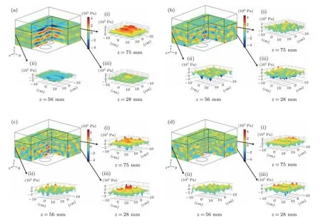
Fig.3. Acoustic field distribution in the XY plane at the stirring speed of(a)0 rpm,(b)300 rpm,(c)600 rpm,and(d)2000 rpm.
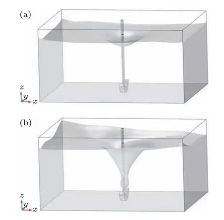
Fig.4. The vortexes generated at(a): Rs=600 rpm and(b): Rs=2000 rpm.
To verify the simulation results, the experimental results are shown in Fig. 5. From Fig. 5(a), it can be seen that the change in absorbance of the solution under agitation condition is much higher than that without agitation. Under the ultrasound radiation alone,the sonochemical reaction can only occur at the antinode of the standing wave in the reactor. The agitation eliminate the standing wave in the reactor and allows the ultrasonic waves to radiate evenly throughout the reactor,which improve the reaction rate significantly. In addition to that, the flow of liquid also increase the rate of sonochemical reactions for two main reasons. One reason is that the flow of liquid avoids the aggregation of active bubbles in the standing wave field thanks to the disturbance of the primary and secondary Bjerknes forces, and it provides the acoustic field with the reactants and nuclei required to form active bubbles.Moreover,it enhance the mass transport of reactant.[24,25]
Aside from that,it is also noticeable that the degradation rate of the solution increases with stirring speed up to its maximum value at 600 rpm, and once that limit is reached, it decreases with increased stirring speed. Figure 5(b) illustrates the absorbance of the solution at the stirring speed of 600 rpm.It is interesting to note that the absorbance peak is near 600 nm where 91%of the degradation rate is achieved.Next in this essay, the influence of stirring speed on the degradation rate of the solution will be analyzed through the flow field distribution.
In order to investigate the influence of the stirring speed on liquid velocity distribution,simulation models with different stirring speeds are calculated. As presented in Figs.6(a)–6(d), the white flow streamlines and colored one(s) on the figure respectively represent the velocity direction and magnitude. The flow velocity in the flow field without agitation is very small compared to agitation and the flow velocity in the flow field increases with the increase of the stirring speed.Meanwhile,the maximum flow velocity in the whole flow field is located around the agitator, and the flow velocity in theYZplane remains rather small atx=120 mm. Thus, it can be concluded that in the flow field,the area influencing the most of the generation of cavitation are located atx=0 mm andx=37.5 mm. However, when the flow velocity becomes too large, the rate of sonochemical reaction will be reduced. It is due to the pressure caused by the high velocity fluid flow which leads to cavitation bubbles bursting before collapsing,thus reducing the cavitation effect.
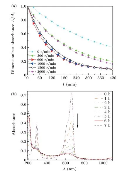
Fig. 5. The experimental results: (a) the dimensionless absorbance of the solution versus time under different stirring speeds and (b) under different time points,the absorbance of the solution as a function of wavelength at the stirring speed of 600 rpm.

Fig.6. Liquid velocity distributions in the YZ plane at the stirring speed of(a)0 rpm,(b)300 rpm(c)600 rpm,and(d)2000 rpm.
4. Conclusion
In this paper,the distribution of the flow field and acoustic field were obtained through numerical simulation, and the relationship between the degradation rate and the two fields were summarized, that is, agitation can make the distribution of the acoustic field more uniform,increase the cavitation area and finally a stirring speed is too high and is not conducive to the generation of the cavitation effect. Then the degradation experiment was designed using those simulations,and the experimental results presented the degradation rate of the solution as first increasing and then decreasing with the increase of stirring speed. The concordance of simulation results with experimental ones not only explains why the solution’s degradation rate is increased by stirring solution in theory but also makes it possible to predict the solution’s degradation rate using numerical methods,which could help save time and reduce costs.
猜你喜欢
杂志排行

Chinese Physics B的其它文章
- Physical properties of relativistic electron beam during long-range propagation in space plasma environment∗
- High winding number of topological phase in non-unitary periodic quantum walk∗
- Widely tunable single-photon source with high spectral-purity from telecom wavelength to mid-infrared wavelength based on MgO:PPLN∗
- Control of firing activities in thermosensitive neuron by activating excitatory autapse∗
- Adaptive synchronization of chaotic systems with less measurement and actuation∗
- Dynamics analysis of a 5-dimensional hyperchaotic system with conservative flows under perturbation∗