Hardware-in-the-Loop Simulation of Vibration Control of Stay Cables with Damper Based on dSPACE System
2021-09-07ZHOUQunmei周群美CHENGPengju程鹏举PENGWei
ZHOU Qunmei(周群美), CHENG Pengju(程鹏举), PENG Wei(彭 卫)*
1 School of Civil Engineering & Architecture, Jinhua Polytechnic, Jinhua 321017, China
2 School of Civil Engineering & Architecture, NingboTech University, Ningbo 315100, China
Abstract: A simple and economical method based on dSPACE system is developed to measure the effect of cable vibration control. The experiments, numerical simulation and hardware-in-the-loop (HIL) simulation are carried out for the vibration control of stay cables with dampers. Firstly, the test results of solid cable vibration under harmonic excitation are compared with the numerical simulation results of cable vibration to ensure the correctness of the simulation of cable module. Then, the vibration test results of solid cable with damper under harmonic excitation are compared with the numerical simulation results of solid cable with damper to ensure the correctness of the relevant modules. Finally, the external load and the cable are imported into the real-time simulation system to simulate the control effect of the damper under the current excitation in real time. The results show that the simulation is correct and the HIL simulation is feasible in the bridge engineering.
Key words: stay cable; vibration control; dSPACE system; hardware-in-the-loop (HIL) simulation
Introduction
Hardware-in-the-loop (HIL) simulation is a simulation method widely used in various fields, especially in military industry, automobile industry, aerospace and other industries in line with modern technology. Linjamaetal.[1]analyzed the possibility of using simulation model to test controller hardware and simulation model to replace hydraulic and mechanical parts of hydraulic position servo. After that, Bullocketal.[2]proposed the motivation of using HIL simulation program, considering the “correctness” of the real-time model and the timeliness of interaction with external control devices. Carrauetal.[3]introduced the method from model to HIL. Nguyenetal.[4]proposed collaborative simulation and HIL simulation, as well as the integration of HIL to a co-simulation framework, which could be closer to the comprehensive and real evaluation and verification of smart grid. García-Martínezetal.[5]provided an on-line database to allow experiment reproduction for power HIL test information.
Smolinskietal.[6]carried out research in the field of medical engineering in minimally invasive surgery. Wang and Bai[7]used HIL real-time simulation system to design and develop an air suspension hardware loop simulation experimental platform for vehicle model and suspension control algorithm. Traphöneretal.[8]proposed a suitable HIL control framework by combining vehicle dynamics model with hybrid motion/force control of manipulator system. Mocera[9]studied the design of an HIL simulation platform for hybrid agricultural tractors to evaluate the performance of different tasks from experimental measurements. Shaoetal.[10]used HIL test bench to test connected and autonomous vehicles (CAVs) and other types of vehicles under various road conditions, which could provide an effective and economical method.
Schulteetal.[11]proposed a hardware in loop HIL test-bed system to improve the fault-tolerant control (FTC) scheme of offshore wind turbines, and verified it with the actual conditions. Huangetal.[12]proposed hardware simulation in HIL building, which was lower than the field test cost of occupied building simulation, and introduced speed control of forced draft fan of heating, ventilation and air conditioning (HVAC) system in variable air volume (VAV) building, and explained the application of HIL simulation framework. Júnioretal.[13]applied the real-time simulation of control hardware in HIL to the control of multifunctional inverter in microgrid. Mehrfeldetal.[14]developed a dynamic test method using hardware in HIL concept to control energy conversion system.
Cables are critical component of cable-supported structures such as cable-supported buildings and stadiums, cable-stayed bridges, and suspension bridges[15]. In-service cables are vulnerable to fatigue and corrosion damage withstanding dynamic loads such as cyclic traffic loads on bridges, wind loads, and other operational loads and environmental effects. Mitigation of wind-induced vibrations in tall buildings and large span bridges has been taken seriously for decades for the safety of the load bearing members, nonstructural elements, and the building envelope, as well as for the comfort of the occupants[16-17]. Among various technologies to mitigate these vibrations, tuned mass dampers with various improvisations, active or semi-active controls, and viscous dampers are proposed and used extensively[18-19]. However, the application of HIL in bridge engineering is at an early stage.
In this paper, a unified excitation is set, the physical simulation of a single cable and the cable with damper are carried out respectively, and then the numerical simulation of single cable and cable with damper is carried out.
1 Experimental Preparation
In this experiment, the similarity ratio of the model is considered in three aspects: geometric similarity, material similarity and dynamic similarity. In the calculation process, the proportion is determined by dimensional analysis.
The physical quantities to be considered in the dimensional analysis of this paper are shown in Table 1.
Table 1 Physical quantity and dimension
The length of the researched stay cable is 330 m, the nominal cross-sectional area is 6 273 mm2, and the theoretical weight of steel wire bundle is 52.5 kg/m. After considering the similarity principle of the model, the scale ratio of steel wire rope is 1∶100. Therefore, the length of the test object is 3.3 m. In addition to the length similarity, it is also necessary to consider the similar mass. A certain amount of additional mass block should be added to the wire rope, and the mass block should be fixed uniformly along the wire.
The scale wire rope is
Sarea=6 273/1002=0.6273 mm2.
The additional mass is evenly added to the steel wire rope. Therefore, customized small cylindrical counterweights are added to all cables and evenly distributed on the cables. The shape of cylindrical counterweights is shown in Fig. 1. The size of the counterweight is made of carbon steel plate with an outer diameter of 30 mm, an inner diameter of 2.4 mm and a thickness of 10 mm. The middle hole is perforated, and the steel wire rope is wound through the hole. The thin steel wire is used at the hole to increase the friction resistance, and the cast iron counterweight block is clamped to avoid displacement during vibration. The cable clamp is shown in Fig. 2, and the general arrangement of the cable vibration test is shown in Fig. 3. The height of the whole wire rope is about 1.43 m, the horizontal length is about 2.97 m, and the angle of inclination is about 25.7°.

Fig. 1 Shape of cylindrical counterweight

Fig. 2 Cable clamp
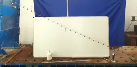
Fig. 3 General arrangement of cable vibration
2 Cable Vibration Test
2.1 Vibration test of the cable without damper
The modal frequencies of the cable are shown in Table 2. The vibration of the cable is mainly concentrated in the first three orders, so the vibration monitoring instrument needs to monitor enough data within 1 s to prevent peak clipping.
In this test, due to the light weight of the cable and the small damping, the contact measuring instrument has a certain tension. In terms of the magnitude ratio, the contact instrument will have a greater impact on the scale test, so the contact measuring instrument can not be used for data recording. Based on the above problems, this paper considers using camera to record vibration data, and the balance position of the measuring point is in the same horizontal plane as the camera. In the test background, a steel ruler is arranged with a white board, which is parallel to the cable, and the displacement of the middle point of the span is recorded by camera. The recording time in this test is 240 frames/s, and sufficient data can be monitored within 1 s to avoid multiple peak clipping phenomenon. Through Matlab the image fixed-point recognition and a single image block as the recognition object are established, and all the pictures are read and the image block are matched. The vibration test results of the undamped cable are shown in Fig. 4.
With the increase of vibration time, the vibration amplitude decreases and the frequency remains unchanged. The rope decays rapidly in 0 to 8 s of free vibration, and the attenuation rate decreases with the increase of time, and then decreases to a vibration range of smaller amplitude after 8 s.
2.2 Vibration test of cable with damper
In this test, the cable displacement meter of Yangzhou Kedong Electronics Co., Ltd. (Yangzhou, China) is used to replace the damper. There are two points in using displacement meter to replace damper: firstly, there is a certain restoring force in the pull wire type displacement meter, which satisfies the requirements ofF=kx(k=2.5 kN/m).This restoring force can be adapted to the force generated by the step excitation of steel wire rope in this test. Compared with linear variable differential transformer (LVDT) linear displacement meter, the pull wire type has smaller restoring force and easier connection with thin wire rope. Secondly, the pull-out displacement meter can record the vibration state of the pull-down rope, which can be transmitted to the hardware in loop real-time simulation system called dSPACE as an output, which corresponds to the semi-physical simulation mentioned later.
The cable-type displacement meter is connected with MicroLabBox of dSPACE and can collect displacement data of the displacement meter to the dSPACE system. The dSPACE is the equivalent of a walking "brain" that integrates a series of functions such as a processor, memory, and reader. In the test, it can read the sensor data with current as the transmission signal in real time, or output the required voltage and current through fast internal calculation. The application of dSPACE in this section is mainly to process and collect data from cable-type displacement sensors. According to the sensor parameters given by Yangzhou Kedong Electronics Co., Ltd. (Yangzhou, China), the actual displacement is obtained. In the tests in this section, the transmission and acquisition of signals are shown in Fig. 5. The measured results are shown in Fig. 6.

Fig. 6 Time displacement of cable vibration with damper
Compared Fig. 6 with Fig. 4, the difference between damped and undamped cable vibrations is evident, and the amplitude of the damped cable is reduced to a very small vibration range within 1 s.
3 Simulation of Cable Vibration
3.1 Vibration simulation of bare cable under step excitation
In this section, Matlab script and Simulink are used to simulate the vibration of single cable under excitation. The connections among incentives are established by Simulink. In Simulink, step is used to simulate the step excitation under the instantaneous concentrated load. The step time of step is controlled to be 0.001 s, and then the input is stopped, so that the cable can be simulated the actual vibration under the step excitation. The simulation results are shown in Fig. 7. Through the comparison between the actual test and the simulation test, the simulation in this paper is consistent with the actual state.

Fig. 7 Time displacement of mid-span vibration in simulated cable test
3.2 Vibration simulation of damper cable under step excitation
In this section, Matlab script and Simulink are mainly used to simulate the vibration numerical simulation under single cable and external damping combination. The simulation configuration is shown in Fig. 8. The simulation results are shown in Fig. 9, where “Original envelope 1” represents the lower boundary of the calculated amplitude and “Original envelope 2” represents the upper boundary of the calculated amplitude.

Fig. 8 Calculation configuration of external damper
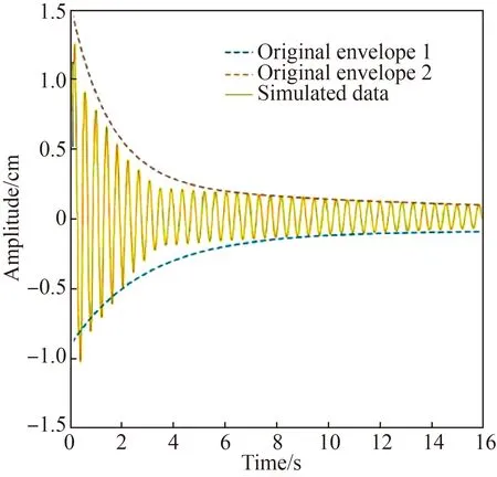
Fig. 9 Time displacement of mid-span vibration in simulated cable and external damping test
4 HIL Simulation of Cable Vibration Based on dSPACE MicroLabBox
By introducing the semi-physical simulation into the cable vibration control test, a method which takes into account the advantages of both field test and numerical simulation can be obtained, so as to restore the field well under the condition of low cost and low time period.
The semi-physical simulation method is applied to the cable damper system, which can test not only the performance of the damper, but also the damping performance of the cable. The HIL simulation block diagram is shown in Fig. 10.
On the whole, the relationship between external load, the cable and external damping is shown in Fig. 11. From the perspective of HIL simulation, the three blocks can be divided into two parts. Under natural conditions, the complex external load and the cable vibration caused by the load are regarded as the physical part, and the damping part as the virtual part. In the process of the test, some actual physical states are captured by different sensors and transmitted to the MicroLabBox to carry out the simulation framework. The obtained contents and actual data are displayed in the control desk of the computer stand. The biggest advantage of this method is that the influence of complex external load on the cable is relieved, and the complexity of field test is simplified.

Fig. 10 Block diagram of semi-physical simulation test
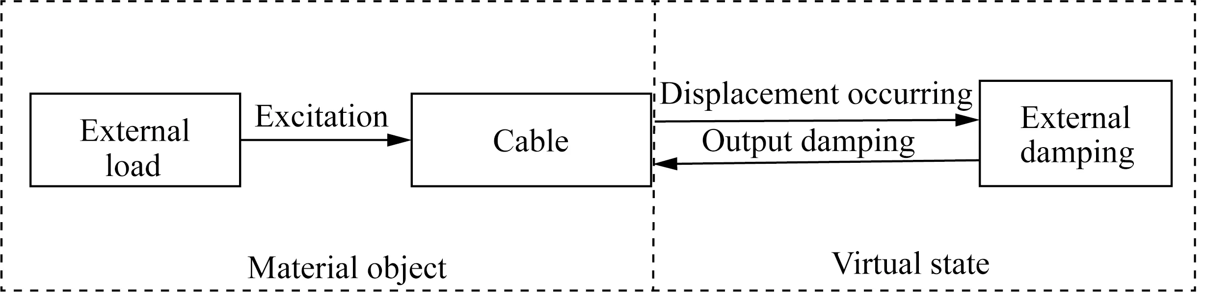
Fig. 11 Logic relation of semi-physical simulation
First of all, a simple mode is constructed by the above frame, which can be divided into four modules according to the flow chart in Fig. 12, which are the analog to digital converter (ADC) of sensor D electrical signal input, the module of electric signal to data, the module of establishing state equation, the module of calculating output and the output result. In Fig. 12, dis_v represents the real displacement and dis_v1 represents the simulated displacement. In this paper, the ADC module of dSPACE is the signal access terminal of the real world. The signal comes from the data entry of MicroLabBox. When it is connected with any sensor, the voltage signal data of sensor is transmitted to the computer through the interface of MicroLabBox. The signal obtained by ADC module is the electrical signal input by the sensor. Therefore, conversion should be carried out according to the relationship between measurement and voltage given by the manufacturer, that is, “convert the electrical as a displacement signal” and “convert the electrical as a speed signal” on the diagram, which is V_ dis on the graph. The four output scopes are the original mid-span displacement, the original damping displacement, the original mid-span displacement after adding damping and the displacement of damping position after adding damping.

Fig. 12 Simulink diagram of vibration control test
We select the connection with rti1202 (the selected model corresponding to MicroLabBox) in Simulink, and select format Build to form a standard delay format (SDF) file and import it to be ControlDesk. At the same time, the variable parameters in the experiment are also dragged into the right side of the observation area to achieve real-time correction and real-time modification. The vibration control test platform is shown in Fig. 13. The mid-span test results are shown in Fig. 14. The overall trend of vibration is the same as that of the damper. However, the vibration after 3 s is slightly larger than the actual situation.
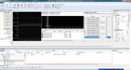
Fig. 13 Vibration control test platform
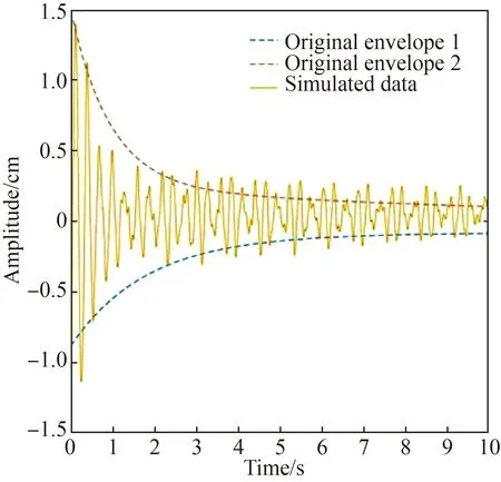
Fig. 14 Semi-physical simulation of vibration reduction
5 Conclusions
Through experiments and HIL simulation, the following conclusions can be drawn.
(1) The free vibration of the tested cable attenuates rapidly from 0 to 8 s, the rate of decay decreases with time, and it decays to a smaller amplitude range after 8 s. However, the cable with damping is reduced rapidly to a very small vibration range after only 1 s.
(2) In the cable test and simulation, the amplitude of the cable is affected by the concentrated load, and the natural frequency is affected by the gravity of the cable and the cable tension.
(3) With the increase of damping, the vibration will be attenuated rapidly, but in the early instantaneous process, the displacement is asymmetric, which is related to the instantaneous dynamic in the initial stage.
(4) The calculation results insert test method based on real-time simulation system are close to the actual situation and reliable, which proves that the HIL simulation test method is feasible. By introducing the semi-physical simulation into the cable vibration control test, a method which takes the advantages of both field test and numerical simulation can be obtained, thus, the project site can be simulated with low cost and low time.
杂志排行

Journal of Donghua University(English Edition)的其它文章
- Surface Modification of Electrospun Poly(L-lactide)/Poly(ɛ-caprolactone) Fibrous Membranes by Plasma Treatment and Gelatin Immobilization
- Probabilistic Load Flow Algorithm with the Power Performance of Double-Fed Induction Generators
- Outage Probability Based on Relay Selection Method for Multi-Hop Device-to-Device Communication
- Channel Characteristics Based on Ray Tracing Methods in Indoor Corridor at 300 GHz
- Electromagnetism-Like Mechanism Algorithm with New Charge Formula for Optimization
- Prediction of Online Judge Practice Passing Rate Based on Knowledge Tracing