Optimal Reactive Power Compensation of Distribution Network to Prevent Reactive Power Reverse
2021-09-07XINGJieCAORuilin曹瑞琳QUANZhaolong权钊龙YUANZhiqiang袁智强
XING Jie(邢 洁), CAO Ruilin(曹瑞琳), QUAN Zhaolong(权钊龙), YUAN Zhiqiang(袁智强)
1 College of Information Science and Technology, Donghua University, Shanghai 201620, China
2 Engineering Research Center of Digitized Textile & Apparel Technology, Ministry of Education, Donghua University, Shanghai 201620, China
3 Shanghai Electric Power Design Institute Co., Ltd., Shanghai 200025, China
Abstract: The capacitive reactive power reversal in the urban distribution grid is increasingly prominent at the period of light load in the last years. In severe cases, it will endanger the security and stability of power grid. This paper presents an optimal reactive power compensation method of distribution network to prevent reactive power reverse. Firstly, an integrated reactive power planning (RPP) model with power factor constraints is established. Capacitors and reactors are considered to be installed in the distribution system at the same time. The objective function is the cost minimization of compensation and real power loss with transformers and lines during the planning period. Nodal power factor limits and reactor capacity constraints are new constraints. Then, power factor sensitivity with respect to reactive power is derived. An improved genetic algorithm by power factor sensitivity is used to solve the model. The optimal locations and sizes of reactors and capacitors can avoid reactive power reversal and power factor exceeding the limit. Finally, the effectiveness of the model and algorithm is proven by a typical high-voltage distribution network.
Key words: reactive compensation planning; high voltage distribution network; power actor; improved genetic algorithm
Introduction
The optimal reactive power planning (ORPP) is mainly to determine the amount and location of shunt reactive power compensation devices needed for minimum cost while keeping an adequate voltage profile[1-3]. The ORPP is a typical nonlinear optimization problem with a large number of variables and constraints[4].
In some studies, fitness functions suitable for multi-objective optimization were constructed, which introduced the numbers of control adjustment or considered multi-area interconnected systems[5-6]. Many efforts have been undertaken using classical optimization techniques[7-9]. Compared with the conventional optimization algorithm, intelligent optimization algorithms have attracted much more attention due to their advantages such as ignoring gradient of optimization model and dealing with discrete variables easily[10-14]. In order to solve the problem of large calculation quantity and long search time for numerous compensation points in distribution network, sensitivity analysis[3]and partition coefficient are used to reduce the candidates before searching. In addition, conventional reactive power planning (RPP) model based on deterministic load is expanded to that of uncertainty operating modes, in order to improve the adaptability of reactive power planning results[15-17]. However, most studies on ORPP are based on the power grid of overhead transmission lines. The capacitance of overhead lines is much smaller than that of underground cables at the same voltage, therefore, the capacitive reactive power reversal is not considered in ORPP[18].
At present, the urban high voltage distribution network shows new characteristics. On the one hand, the load peak-valley difference of power grid increases significantly; on the other hand, due to the restriction of resource and environment, the newly-built lines are mainly large-section underground cables and the old overhead lines are gradually changed to the underground cables. With the further expansion of the scale of high-voltage distribution network, redundant capacitive reactive power flows back to the higher voltage grid under low load condition. It not only raises the system voltage and challenges the voltage regulation ability of substation, but also reduces the stability margin of under excited generator in the power grid, which affects the security and stability of power grid[19]. In the power grid, reactive power compensation is proceeded according to hierarchical balance. For a long time, the redundant capacitive reactive power of 110 kV grid is compensated by 35 kV or 10 kV reactors in 220 kV substations. There are usually no reactors in 110 kV substations. On the other hand, the main purpose of 110 kV high voltage reactor installed at long transmission line is to limit overvoltage rather than to balance reactive power. The centralized installation of capacitive and inductive compensation in 220 kV and above substations has gradually failed to meet the requirements of distribution network development[20]. Considering the difficulty of project implementation and practical economy, it is an effective and feasible method to integrate capacitors and reactors in the 10 kV sides of 110 kV substations.
Taking Shanghai power grid as an example, in 2018, the daily maximum peak-valley difference reached 12 630 MW, accounting for 48.5% of daily maximum load. The total length of 110 kV underground cables in Shanghai power grid was 1 611 km, accounting for 42% of all 110 kV lines. Under the new development trend, the RPP would gradually become the coordinated planning of capacitive and inductive reactive compensation for relieving capacitive reactive power excess being caused by cables at low load condition. Meanwhile, the inequality constraints mainly include voltage constraints, capacitor capacity limits and other traditional constraints in conventional ORPP. However, in the current power grid, excess capacitive reactive power flows back to active power supply source, which often leads to the power factor exceeding the limit at the measurement point of distribution station. Consumers who exceeded the power factor limit have to pay punitive electric bill[21]. Therefore, it is helpful to solve the reactive power reversal and unqualified power factor under low load condition that the power factor constraint is considered into the ORPP.
This paper proposes an ORPP method considering power factor constraints in high voltage distribution network. This paper is organized as follows. Section 1 gives a comprehensive ORPP model with power factor constraints for optimizing the sizing and location of reactors and capacitors. The nodal power factor constraints are added into the mathematical model, which is used to solve the problems of reactive power reversal and power factor exceeding the limits in distribution network. Section 2 gives a brief formula derivation of the sensitivity of power factor to reactive power. Section 3 presents an improved genetic algorithm (IGA) by power factor sensitivity (PFS), in which the traditional genetic algorithm (GA) is improved by taking PFS as the guiding strategy for forming initial population. In section 4, the test and validation of model and algorithm are conducted on test systems. Finally, section 5 concludes the work.
1 RPP Model Considering Power Factor Constraints
1.1 Objective function
The objective of the RPP is to minimize the total cost of active power loss and compensators during the planning period[2].The objective function is shown as
(1)
wheref1is the capacity cost of compensators, which are capacitor investment and reactor investment;f2is the cost of active power loss of distribution network;C1andC2are capacitor’s cost coefficient of unit capacity and reactor’s cost coefficient of unit capacity, respectively;QCiandQLiare the capacity of reactive power resources installed at busi;Tis the planning period; τ is the electricity price per kwh;tis the time of operation;Ploss1andPloss2are the active power loss of network and transformers;NCandNLare the numbers of installed capacitors and reactors.
1.2 Conventional constraints
Because the slack bus is the only reactive power source except compensation in the distribution network, the power flow equation is shown as
(2)
wherePiandQiare the injected active power and reactive power at busi;UiandUjare the voltage magnitudes of busiand busj;Gijis the conductance between busiandj;Bijis the transfer susceptance between busiandj;δijis the voltage angle difference between busiandj;nis the total number of buses;αiandβiare the switch variables with a value of 0 or 1, which decide the operation of capacitors or reactors. Because the capacitors and reactors cannot run at the same time, variablesαiandβicannot be taken as 1 simultaneously.
Constraints of voltage magnitude and transmission line loading are as follows:
(3)
(4)
1.3 Constraints of power factors and compensators
1.3.1Powerfactoraffectedbyreactivepowerflowreversing
In high voltage distribution network, the nodal power factor is measured at the coupling point of substation, which is determined by the suppling load and the power transferred to other substations. Due to the radial structure, the power factor of bus can be calculated by apparent power at the end of incoming line. The nodal power factor and reactive power distribution are different corresponding to overhead lines and underground cables being used in distribution network, even if there is the same active power loss.


Fig. 1 Schematic diagram of chain connection distribution network
As mentioned above, it is necessary to add power factor constraint and consider coordinating reactors and capacitors on the traditional RPP model which mainly focuses on capacitor compensation, so as to solve the problem of reactive power reversal and power factor exceeding the limit under the light load period.
1.3.2Constraintsofpowerfactorandreactivepowercompensation
Capacity constraints of reactive power compensation are shown as
(5)
(6)
The constraint of power factor is shown as
(7)

(8)
where distributed generation (DG) is not considered in the proposed model, so there is no active power sent to grid andPiis positive; sgn (Qi) is “1” whenQiis absorbed by load, otherwise it is “-1” and negative sign is used to indicate the reverse direction of reactive power flow. In this way, compensation schemes with reactive power reverse are excluded from the feasible solutions because they cannot meet power factor constraints. The new added constraint prevents reactive power flow reversely.
2 IGA for the Proposed Model
GA is an adaptive search algorithm simulating biological evolution, which does not need the gradient information of model. GA can obtain the global optimal solution in probability through the operation of selection, crossover and mutation[14].
In this paper, the traditional GA is improved according to the characteristics of the planning model.
2.1 Chromosome code mapping to Gray code
In this paper, the traditional GA is improved according to the characteristics of the planning model. In order to save memory space, improve computing speed, and avoid Hamming cliff problem approaching the optimal solution, the definition domain of discrete control variables is mapped to gray code. In this way, the approximation can be avoided when the optimal chromosome is decoded between adjacent control variables. And the Gray code can also prevent probability density from being affected by the invalid solution in selection process, because the number of chromosomes produced by traditional binary code is larger than that of feasible solutions.
2.2 Forming effective initial population
2.2.1PFSwithrespecttoReactivePower
The PFS is obtained by the partial derivative of power factor to the reactive power injection at the end of branch. PFS can reflect the influence of reactive compensation variation on nodal power factor. It can be seen from Fig. 1 that the power factor of busiis not only determined by the suppling load, but also affected by the load of other buses connected with it. The PFS of nodeito reactive power of network is shown as
(9)
where ∂cosφi/∂Piand ∂cosφi/∂Qican be calculated according to the power factor definition formula; ∂Pi/∂Qand ∂Qi/∂Qare the partial derivatives of injection power at busiwith respective to reactive power vector, which can be calculated by ∂Ui/∂Qj, ∂Uj/∂Qj, ∂δi/∂Qjand ∂δj/∂Qjfrom Jacobi matrix.
2.2.2FormingeffectiveinitialpopulationwithPFSselectionstrategy
When an initial population is formed, the reactive power compensations of chromosomes which exceed the power factor limits, are adjusted to meet the power factor constraints according to the results of PFS.
Initial population is generated randomly in control variable domain. Then, for each chromosome that do not meet the power factor constraint, the sensitivities of over-limit power factor with respect to gene segments (compensation locations) are calculated according to Eq. (7) and sorted by their absolute values. The reactive power compensation with the largest PFS is adjusted by the direction of sensitivity change. If the compensation capacity is at the boundary, the reactive power compensation adjustment is carried out on the gene segment with the second largest PFS value until the power factor meets the constraints.
2.3 Algorithm flow
The main steps of the IGA are as follows.
Step1Input network data and set parameters of IGA, such as maximum generation, population size, crossover probability and mutation probability.
Step2Form initial population.
Step3Reproduce chromosomes into a “mating pool” according to their fitness values by roulette wheel.
Step4Perform crossover to each couple of chromosomes in the “mating pool” according to the crossover probability. Apply crossover operation successfully if power factors meet limits; otherwise keep chromosomes unchanged.
Step5Perform mutation according to the mutation probability. Apply mutation operation successfully if power factors meet limits; otherwise keep chromosomes unchanged.
Step6Stop the procedure and output the results if the convergence criterion is satisfied; otherwise go back to Step 3.
3 Case Study
In this section, the effectiveness of the proposed model and algorithm is tested using IEEE 14-bus test system. The system configuration is shown in Fig. 2 and the line data of system can be found in Appendix.

Fig. 3 Capacity of reactive power compensation
The network voltage is 110 kV. The limits of voltage magnitude are taken between 0.94 and 1.06 (per unit value) for all buses except the slack bus1. The capacity of each transformer is 50 MVA. Its load lossPkis 194 kW and short circuit impedance is 10.5%. At light load condition, the active and reactive power of buses are shown in Appendix. The reactive power compensation of each bus is grouped into 3 Mvar and 5 Mvar according to the actual equipment capacity.
The IGA program in this paper is realized using MATLAB. The parameters set in algorithm are as follows: population size is 50, maximum generation is 15, crossover probability is 0.8 and mutation probability is 0.09. In the proposed RPP model, the planning period is 10 a, electricity price is 0.45 CNY/(kW·h), the unit capacity price of capacitor is 50 CNY/kvar, the unit capacity price of reactor is 80 CNY/kvar, the light load availability hours are 2 600 h and the range of power factor is [0.9, 1.0]. Because the use of 10 kV reactor in 110 kV substation has not been normalized, the price of reactor per unit capacity is higher than that of capacitor.
In initial network without any reactive power compensation, the reactive power flowing into the slack bus is 18.16 Mvar and the total number of buses that violate power factor constraints is 3.
The results of the proposed method in this paper are shown in Table 1.
The results in Table 1 show that the objective function is 567×104CNY and the capacities of capacitors and reactors are respectively 6 Mvar and 26 Mvar. In this paper, the coordinated planning of reactor and capacitor is considered, which eliminates the problem of power factors exceeding the limits and reduces the reactive power of 18.16 Mvar to the upper power grid. Considering the huge scale of the actual high-voltage distribution network, the optimization results will be more obvious, which can effectively reduce the voltage regulation pressure of power grid.
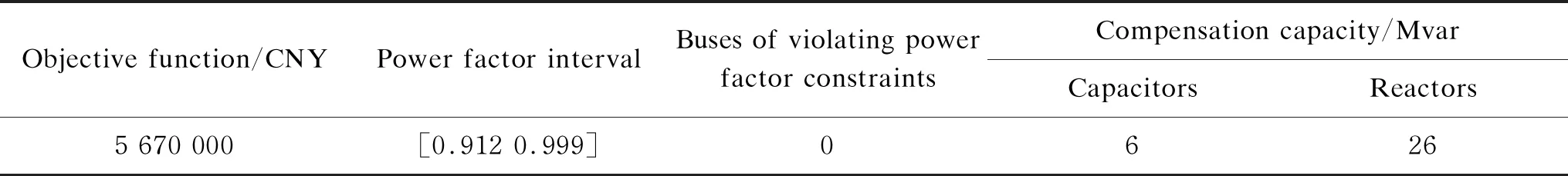
Table 1 Compensation results of the proposed RPP model
Table 2 shows the improvement effect on reactive power reversal and power factors exceeding the limits in the proposed planning scheme. The negative sign indicates that the reactive power flows back into the bus.
From the comparison in Table 2, it can be found that several nodal power factors in the original network are lower than 0.900, such as bus5 and bus9, and there is reactive power reverse in some buses, such as bus2, bus6 and bus11. The optimal results of RPP considering power factor constrains and coordination of capacitors and reactors, can avoid reactive power reversal and power factor exceeding the limit.

Table A1 Loads of buses

Table A2 Line parameters
Figure 3 shows the optimal sizing of capacitors and reactors at low voltage buses of substations. In order to express clearly, shunt capacitors compensation is positive and reactor compensation is negative.
The comparison of voltage profile is shown in Fig. 4. It can be found that the voltage profile of the proposed RPP is improved, which is much better than that of original network. The maximum voltage magnitude is reduced and the voltage gap is smaller. The sample standard deviations of two voltage fluctuation curves are 0.108 9 and 0.039 9, respectively. The results show that the network voltage fluctuation is smaller when reactive power compensation is carried out according to the planning scheme.

Fig. 4 Voltage profile comparison

Fig. 5 Convergence curve of IGA
Figure 5 shows the convergence characteristics of the objective function of the proposed IGA method.
4 Conclusions
In this paper, an improved RPP model with power factor constraints is proposed, in which capacitors and reactors are considered coordinately. The objective function is the minimization of real power loss and compensation cost during the planning period and new constraints such as nodal power factor limits and reactor capacity constraints are taken into account. Then, PFS with respect to reactive power is derived. An IGA by PFS is used to solve the model. Finally, the effectiveness of the model and algorithm is proven by a typical high-voltage distribution network. The results show that the proposed method can avoid reactive power reversal and power factor over-limit in the conditions of light load and large-scale underground cables in the high-voltage distribution network.
杂志排行

Journal of Donghua University(English Edition)的其它文章
- Surface Modification of Electrospun Poly(L-lactide)/Poly(ɛ-caprolactone) Fibrous Membranes by Plasma Treatment and Gelatin Immobilization
- Probabilistic Load Flow Algorithm with the Power Performance of Double-Fed Induction Generators
- Outage Probability Based on Relay Selection Method for Multi-Hop Device-to-Device Communication
- Channel Characteristics Based on Ray Tracing Methods in Indoor Corridor at 300 GHz
- Electromagnetism-Like Mechanism Algorithm with New Charge Formula for Optimization
- Prediction of Online Judge Practice Passing Rate Based on Knowledge Tracing