Spectral polarization-encoding of broadband laser pulses by optical rotatory dispersion and its applications in spectral manipulation*
2021-07-30XiaoweiLu陆小微CongyingWang王聪颖XuankeZeng曾选科JiaheLin林家和YiCai蔡懿QinggangLin林庆钢HuangchengShangguan上官煌城ZhenkuanChen陈振宽ShixiangXu徐世祥andJingzhenLi李景镇
Xiaowei Lu(陆小微) Congying Wang(王聪颖) Xuanke Zeng(曾选科) Jiahe Lin(林家和)Yi Cai(蔡懿) Qinggang Lin(林庆钢) Huangcheng Shangguan(上官煌城)Zhenkuan Chen(陈振宽) Shixiang Xu(徐世祥) and Jingzhen Li(李景镇)
1Shenzhen Key Laboratory of Micro-Nano Photonic Information Technology,Key Laboratory of Optoelectronic Devices and Systems of Ministry of Education and Guangdong Province,College of Physics and Optoelectronics Engineering,Shenzhen University,Shenzhen 518060,China
2Collaborative Innovation Center for Optoelectronic Science and Technology,International Collaborative Laboratory of 2D Materials for Optoelectronics Science and Technology(Ministry of Education),Institute of Microscale Optoelectronics,Shenzhen University,Shenzhen 518060,China
Keywords: ultrafast optics,optical rotatory dispersion,spectral polarization-encoding,spectral manipulation
1. Introduction
It is well known that ul trashort light pulses have inherent broad spectral bandwidth, which provides us with great convenience to implement spectral manipulation or shaping.Consequently, femtosecond pulse shaping has attracted an increased interest due to its important applications in many fields including ultrahigh speed communications,[1,2]ultrafast optical signal processing and computing,[3]ultrafast nonlinear processes,[4,5]ultrafast optical imaging,[6,7]precise optical metrology,[8,9]quantum coherent control,[10]high efficient terahertz pulse generation,[11]and chirped-pulse amplification(CPA).[12,13]Until now,many methods for femtosecond pulse shaping have been reported. For example, spatial light modulator[14]and fiber Bragg grating[15]were used for ultrahigh speed communications,whereas etalons,[16]wavelengthdependent reflectors,[17]birefringent plates,[18]and acousticoptical programmable dispersive filters[19]were applied in CPA systems to alleviate spectral narrowing effects.
This paper proposes a novel way to implement femtosecond pulse shaping, which, similar to the spectral timeencoding in CPA, is a kind of spectral polarization-encoding(SPE)for ultrashort light pulses. SPE can be realized simply by allowing a linearly polarized broadband light pulse through some optically active crystals to induce some optically rotatory dispersions(ORD).As a result,all spectral components of the ultrashort pulse are still linearly polarized but their polarization directions can be manipulated by controlling the ORD.This SPE can be decoded by compensating ORD,which is important for some of its applications,e.g.,broadband light pulse amplification,spectral shaping,and so on.
2. Theory and proof-in-principle experiments
An ultrashort light pulse has inherently very affluent spectral components. For a transform-limited pulse,when it propagates through a disperser,it becomes a chirped pulse,and its affluent spectrum allows its temporal duration to be stretched.As a result, in different temporal slices, one will “see” different frequencies inside the chirped pulse. This process can be regarded as a spectral time-encoding. Traditionally, these spectral components have an identical polarization. However,polarization is one of the most important freedoms of a light pulse,so it is very interesting to encode the polarization direction of all the spectral components of an ultrashort light pulse,which,fortunately,can be simply realized by inducing ORD.
As we know,a linearly polarized light beam can be seen as the overlap of left circularly polarized and right circularly polarized components. When the beam goes through an ORD medium,the two components will travel with different velocities. Consequently,the output beam still keeps its linear polarization but rotates its polarization direction by a wavelengthdependent angle with regard to that of the input beam due to ORD. Consequently, we can actualize SPE for a broadband pulse. One of the simple ways to induce ORD is to allow a light pulse through some optically active substances.It is an entirely passive method and very easy to be aligned,meanwhile,unlike the magnetic ORD due to Faraday effect,it works without need of any applied fields.
When a linearly polarized beam at wavelength ofλpasses through an optically active substance with thickness ofL,the rotating angle can be expressed as

Hereα(λ)andη(λ)stand for rotating angle and rotation coefficient,respectively. Both of them are wavelength-dependent.One can see that ORD stems fromη(λ)is proportional to the thicknessL. Accordingly, if the input is a linearly polarized pulse with broad bandwidth, after through an ORD crystal,different spectral components of the pulse correspond to different polarizations,i.e., SPE. Obviously, we can manipulate SPE orα(λ)by changingη(λ)or/andLof an optically active crystal.
The ORD generated by this way is compensable, so our SPE can be decoded,which is important in some applications,e.g.broadband pulse amplification. One way to compensate ORD is to allow the broadband pulses with ORD through another optically active substance which has a rotation coefficient of-η(λ) and an equal thickness of the crystal to generate ORD(Fig.1(a)). Fortunately,this compensation is practicable because some of the optically active substances,e.g.,quartz, have two mirror-symmetrical configurations: the lefthanded and the right-handed, which have opposite values ofη(λ) with each other. We call this decoding method as LR method. Another way to realize ORD compensation is shown in Fig.1(b)including only single crystal puls a mirror,which we call SCM method. There, the ORD is generated from the first pass through a piece of rotatory crystal,and can be compensated automatically to bounce the beam back through the same crystal again with a mirror.
Besides these two ways,we propose another way to compensate ORD, which, as shown in Fig. 1(c), includes double complete same ORD plates plus a broadband half-wave plate(BHW) between the two plates, and we call this decoding as DCW method. It is an all-transmission method which combines the advantages of the two other methods.Here the BHW is firstly aligned so that its fast or slow axis along with the polarization direction of input pulse without the ORD crystal(ORDC)there.Suppose the ORDC will rotate the polarization direction of its incident light pulse with an angle ofα(λ),the light beam will pass though the BHW following the ORDC with a cross angle ofα(λ)between its polarization direction and the fast or slow axis of the BHW.After passing through the BHW, the rotation angle becomes-α(λ) orπ-α(λ), which means that the ORD can be removed by inducing another rotatory angleα(λ),or passing through another complete same ORD crystal as the first one.If the fast axis of BHW is at an arbitrary angleθrelative to the input polarization,after passing through BHW,the polarization direction is 2θ-α(λ),SPE can also be decoded by the second ORDC,except the polarization direction rotates to 2θ.
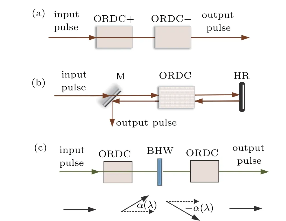
Fig.1. The ways to compensate ORD:(a)using another crystal with mirrorsymmetrical configuration(LR),(b)reflecting the light beam back to the substance(SCM),or(c)using two complete same ORD plates plus a broadband half-wave plate (DCW). ORDC: ORD crystal; ORDC+ and ORDC-: two ORD plates with the same ORD value but opposite signs;BHW:broadband half-wave plate;M:mirror;HR:0° high reflective mirror.
Proof-in-principle experiments are implemented for three decoding methods as shown in Fig.1,using a commercial femtosecond laser oscillator(Mirca-5, Coherent Co.) as the light resource. The oscillator exports 80 MHz, 780 nm, 400 mW pulse chain with a tunable bandwidth from 60 nm to 100 nm.A piece of left-handed quartz with a thickness of 20 mm is used for encoding. The rotation coefficient of quartz at 0.78 μm is about 12 deg/mm,and the rotating angle at 0.78 μm isα(0.78 μm)=241 deg. After encoding, the wavelengthdependent rotating angle of the polarization is shown by the purple line in Fig. 2. When wavelength varies from 0.72 to 0.88 μm, the rotating angle decreases from 285.1 deg to 187.6 deg,close to a linear trend. Another 20-mm quartz with the opposite/same chirality is used for decoding in the configures of LR or DCW,respectively. All the elements,including the mirrors and the wave plate, are using broadband design.By applying a linear polarizer and a spectrograph (HR4000,Ocean Optics,Inc.) at the output side in the three designs respectively,the output spectra(solid lines)and the corresponding transmissions(dotted lines)are shown in Fig.2. The thick gray line stands for the input spectrum. It is obvious that the compensated spectra coincide well with the original one and their transmissions are nearly constant of 1(normalized),which shows that all three designs can operate well for SPE decoding.
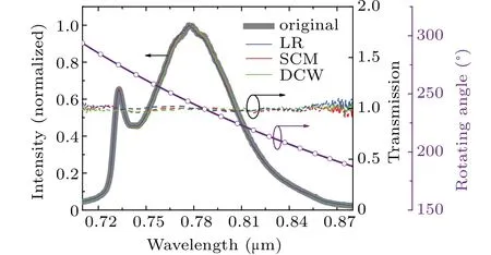
Fig. 2. Experimental ORD compensation results for LR (blue lines), SCM(red lines),and DCW(green lines),solid lines are spectra versus wavelength and dotted lines are transmission versus wavelength.
3. Applications
3.1. Spectra shaping
It is well known the transmission of a linear polarizer is polarization-dependent, so SPE by the aid of a polarizer can work to manipulate wavelength-dependent transmission,thereby realize the spectra shaping of broadband pulses.
As shown in Fig.3,when a linearly polarized broadband pulse passes through a BHW and an ORDC, each spectral component of the pulse has its own polarization direction due to ORD,thereby has its own transmission. Here the BHW before the ORDC is used to rotate the polarization directions of all input spectral components with an identical angle (-α0),thus the spectral component (λ0) with the maximal transmission can be chosen flexibly.The rotatory angle after the ORDC and BHW is

Accordingly,the spectral/polarization-dependent transmission of the linear polarizer can be expressed as

Figure 4(a) shows the transmission curvesT(λ) of the setup in Fig. 3versuswavelength (μm) by using a quartz plate as ORD crystal (black:L=5.0 mm; red:L=10.0 mm; blue:L= 15.0 mm; green:L= 20.0 mm; purple:L= 40 mm)when settingα0atλ=0.75 μm. We can see for a fixedα0,the transmission bandwidth decreases with the thickness of the quartz crystal. Accordingly, if using a wedge pair instead of the quartz plate to make the thickness to be alterable,the setup in Fig. 3 can work as a bandwidth-tunable filter. Figure 4(b)shows the shift of the transmission peaks by simply rotating the BHW at differentα0with a 40-mm-quartz as an encoding ORDC.It can be seen obviously that there are multiple transmission peaks in Fig.4(b),and for normal use of the filter,the adjacent interval should be larger than the pulse width. Applying such a spectra shaper to our laser, wavelength-tunable output can easily be realized. Confirmatory experiments are carried out where an 80-MHz, 2.5-nJ pulse with a tunable bandwidth from 60 nm to 100 nm is used as the input and the results are shown in Fig.4(c), where the experimental output spectra (dots) are consistent well with the calculative results(lines). Although the transmissions have multi-peak structure,however, the “free spectrum range”, or the interval between adjacent peaks,is up to 156 nm,which is much wider than the spectral width(72.1 nm)of the laser we used here. Therefore,output spectra present single-peak structures, and the bandwidth is as broad as about 43 nm.
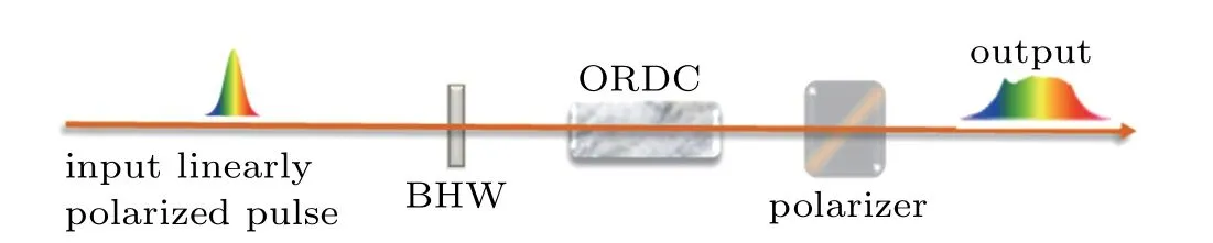
Fig. 3. The setup for spectral shaping. BHW: broadband half-wave plate;ORDC:optically rotatory dispersion crystal.
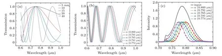
Fig. 4. (a) The transmission versus wavelength (in unit μm) by using a piece of quartz as ORD crystal (black: L=5.0 mm; red: L=10.0 mm; blue:L=15.0 mm; green: L=20.0 mm; purple: L=40.0 mm) for a fixed α0 =α (0.75 μm); and (b) by using a 40-mm-thick quartz for different α0: α(0.800 μm),α (0.791 μm),α (0.765 μm),α (0.781 μm)or α (0.774 μm);(c)theoretical and experimental results of the spectrum versus wavelength(μm).
In addition, the ORD profile can be altered by combination of multiple ORD crystals. The black line in Fig. 5 presents the spectral-dependent rotatory angle of a quartz plate with a thickness of 4.5 mm. One can see that from visible to near-infrared(near-IR),as those of many optically active substances, the|α(λ)| of quartz decreases with wavelength.However,this monotonous trend can be changed by using the combination of multiple ORD crystals. For example, if the combination consists of an AgGaS2plate and a quartz plate with a thickness ratio of 1:5.1,the ORD will exhibit paraboliclike profile(the green line in Fig.5). The blue or red line corresponds to a thickness ratio of 1:4.0 or 1:6.0. Obviously,the ORD profile can be altered by changing the thickness ratio.
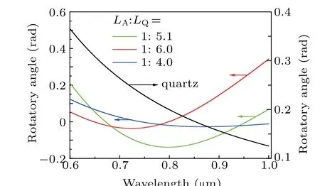
Fig.5.The ORD α(λ)of a piece of quartz crystal(black line),a combination consisting of an AgGaS2 and a quartz plate with different thickness ratios of the AgGaS2 to quartz: 1:5.1(green line),1:6.0(red line)or 1:4.0(blue line).

Fig.6.The transmission versus wavelength(in unit μm)by using a combination of an AgGaS2 plate and a quartz plate for(a)different α0: 0.50(purple),0.94 (red), 3.5 (blue) or 0.0 (dark cyan) with fixed LA: LQ (1:5.1) and LA(2.0 mm), and (b) for different LA: LQ: 1:4.0 (black), 1:4.5 (red) or 1:10.0(blue)when α0=0.0.
In Fig. 6(a), for a given thickness ratio of the AgGaS2to the quartz plates (LA:LQ=1:5.1), the parabolic ORD profile(black line)can be used to achieve not only a flat(purple line,α0=0.5)or saddle shaped(blue line,α0=3.5),but also upward(dark cyan line,α0=0.0)or downward(red line,α0=0.94)parabolic transmission from 0.6 μm to 1.0 μm by tuningα0. For a givenα0,e.g.α0=0.0 as shown in Fig.6(b),the black, red or blue line corresponds to the different thickness ratio of the AgGaS2to the quartz plates:LA:LQ=1:4.0,1:4.5 or 1:10.0(blue),respectively,which means the transmission can also be altered by changingLA:LQ.
From the above discussions,one can see SPE allows us to flexibly manipulate spectral shaping by inducing some spectral polarization-dependent loss,which can be realized through choosing a proper combination of multi-ORD crystals, their thicknesses (the thickness ratio), and a broadband half-wave plate.
3.2. Polarization-encoded chirped pulse amplification
SPE can also help us to manipulate laser gain spectra by the aid of polarization-dependent gain. As we know, some laser crystals have broad polarization-dependent gain spectra,so SPE can be used to control the output spectrum from some lasers. It motivates us to use SPE to suppress efficiently spectral narrowing which is one of the most important but challenging works for a CPA system. Until now,the most popular laser crystal used to boost ultrashort pulse power is Ti:S whose fluorescence bandwidth is broader than 0.2 μm.[20]Even so,the serious spectral narrowing still occurs for a seed with fewcycle pulse duration. Fortunately, the Ti:S has polarizationdependent gain, which allows us to flexibly control amplified spectrum by SPE.As is known,the gain cross-section of Ti:S crystal for theπ-polarized beam is about 2.4 times as large as that for theσ-polarized. Traditionally,the Ti: S amplifiers are designed to amplify their seed pulses withπ-polarization for maximizing laser gain. In order to avoid the spectral narrowing,efforts are usually made to suppress the laser gain for the spectral components around the central wavelength of the seeded pulses, meanwhile, to increase the gain for those far away from the central wavelength. Correspondingly,by use of a BHW and a block of quartz crystal,we applied our SPE to a Ti:S regenerative amplifier[21]where the seed pulses are amplified withσ-polarization for the spectral components around the central wavelength, and withπ-polarization for those far away from the central wavelength.
Figure 7(a)presents our calculations according to Eqs.(1)and (2) and Table 1 of Ref. [21] when using an 11-mmthick quartz plate and setting theσ-polarization wavelengthλσ=0.82 μm. As shown by the blue solid-triangle marks,the amplified pulse bandwidth is initially 44.1 THz,and increases to 49.1 THz with the pass numberNup to 30. In spite that it decreases slightly to 48.1 THz whenNrises to 40,the spectral narrowing is efficiently avoided in the regenerative amplification with an output pulse energy of~3.24 mJ. However,σpolarization amplification for the spectral components around the central wavelength implies some sacrifices of amplification efficiency. Consequently,amplification saturation occurs at pass numberN ≈40 as shown by the black marks.
Furthermore,if a combination consisting of a quartz plate and an AgGaS2plate is used instead of a single quartz plate as the optically rotatory disperser, the ORD profile can become parabolic,so we can set two wavelengths on the opposite sides relative to the wavelength withπ-polarization and the spectral components around the central wavelengths to be amplified away fromπ-polarization. In Fig.7(b),we make numerical simulation basing on the layout in Fig. 1(a) of Ref. [21]with the same equations and initial specifications of Fig.7(a).The thicknesses of the used AgGaS2plate and quartz plate are 8 mm and 47 mm respectively, and the twoπ-polarized wavelengths are set at 0.69 μm and 0.95 μm by rotating the BHW.Figure 7(b)shows the amplifier can still boost the output pulses up to 3.28 mJ without spectral narrowing, butNreduces to 30 for amplification saturation, which means the amplification efficiency has been greatly improved compared with that of Fig.7(a).
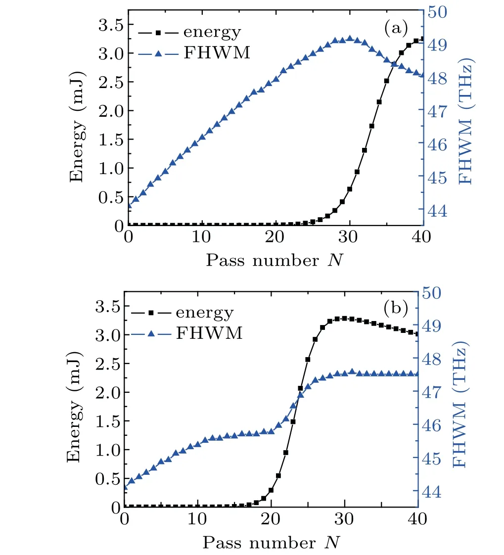
Fig. 7. The evolutions of the amplified bandwidth and pulse energy versus pass number N of the seed through Ti:S regenerative amplifier shown in Fig.1 of Ref.[18]with(a)an 11 mm-thick quartz plate and λσ =0.82 μm,and with(b) an 8 mm AgGaS2 plate plus a 47 mm quartz plate and λπ1 =0.69 μm,λπ2=0.95 μm.
In a Ti:S multi-pass amplifier, we have also set twoπpolarized wavelengths (λπ1andλπ2) by using a block of quartz plate to induce ORD,[22]where theπ-polarized wavelengthλπ1for the odd-numbered amplification is different fromλπ2that for the even-numbered amplification, andλπ1andλπ2are on the opposite sides relative to the wavelength with maximal gain.Calculations show our design can also amplify a 0.8-μm,10-fs seed pulse from sub-nJ to more than 3 mJ without spectral narrowing.What is more,proper ORD allows the setup to output its spectrum to be as broad as 0.149 μm.
The validity of our SPE to manipulate laser gain spectra was experimentally confirmed in a multi-pass[23]and a regenerative[24]amplification systems, where nearly 90-nm broadband amplification was achieved. According to the results described above,our SPE may open a promising way to few-cycle PW-class laser system.
3.3. Application in tunable mid-IR lasers
Obviously, SPE, which can be used to manipulate laser gain/loss,can be also applied for laser tunning.In recent years,3 μm-5 μm mid-IR lasers begin to draw considerable attention due to a variety of important applications in biomedical, material processing, remote sensing, target detection, and other fields. However, compared with those in near-IR and visible regions,the components,e.g.,grating and prism in mid-IR region are much more immature and expensive which are dragging the development of mid-IR tunable laser. Fortunately,SPE allows us to realize the wavelength tunability for a mid-IR laser by just a piece of ORD with good transmission in mid-IR region.
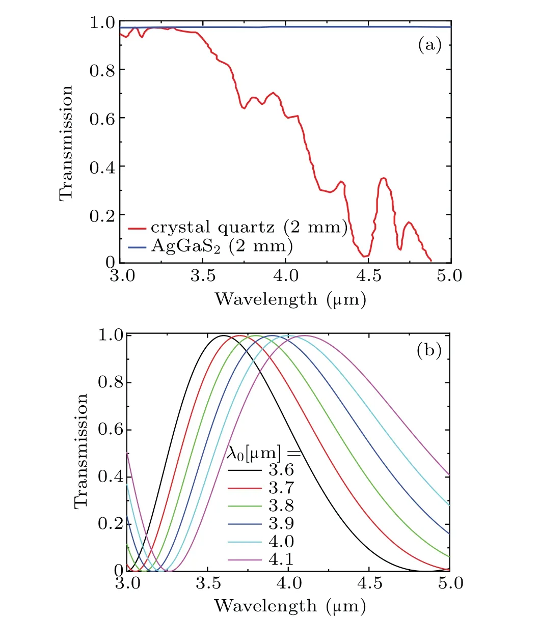
Fig.8. (a)The transmission of quartz and AgGaS2 in 0 μm-5 μm;[25,26] (b)The transmission versus 1/wavelength(1/μm)by using a 15-cm AgGaS2 as ORD crystal.
According to the data from Terahertzlabs,Inc.,[25,26]figure 8(a)presents the transmittance of quartz and AgGaS2with a thickness of 2 mm. We can see the transmittance curve of AgGaS2almost kept a constant of~97%ranging from 3 μm to 5 μm without consideration of Fresnel loss. By contrast,the transmittance of the quartz begins to decrease, and drops to 50%at 4.0 μm.
Similar to the calculations in Fig. 4, figure 8(b) shows the polarization-dependent transmission of a setup according to Fig. 3 with a 15-cm AgGaS2as the ORDC for different maximal transmission wavelengths: 3.6,3.7,3.8,3.9,4.0,and 4.1 μm, which can be tuned by adjusting the angle of halfwave plate as mentioned above. From Fig. 8, AgGaS2is expected to be a promising candidate for wavelength tunning in mid-IR laser.
4. Conclusions
In this paper, a kind of spectral polarization-encoding,or SPE, is proposed for ultrashort light pulses by inducing ORD from some optically active crystals. SPE encodes all the spectral components of a linearly polarized ultrashort pulse with different polarization directions, and can decoded by compensating the corresponding ORD, which is easily realized not only by using a double-pass design, two optically rotatory dispersers with mirror-symmetrical configurations,but also by a combination of another same optically rotatory disperser plus a broadband half-wave plate. By using some ORD crystals plus a linear polarizer, SPE can work to manipulate polarization-dependent transmission for central wavelength or bandwidth-tunable filtering through inducing spectral polarization-dependent loss. SPE can also induce polarization-dependent gain by the aid of some broad polarization-dependent laser media. Applying our SPE to a Ti:S amplifier,we can boost a 0.8-μm nJ-pulse up to mJ level with a bandwidth to support few-cycle pulse duration. This SPE is entirely passive thus very simple to design and align,so it can be used to realize flexibly mid-IR tunable laser beyond 3 μm by using an ORD crystal with a good transmission,e.g.AgGaS2,where the tunning devices are rather under developed compared with those in visible and near-infrared region.
猜你喜欢
杂志排行

Chinese Physics B的其它文章
- Projective representation of D6 group in twisted bilayer graphene*
- Bilayer twisting as a mean to isolate connected flat bands in a kagome lattice through Wigner crystallization*
- Magnon bands in twisted bilayer honeycomb quantum magnets*
- Faraday rotations,ellipticity,and circular dichroism in magneto-optical spectrum of moir´e superlattices*
- Nonlocal advantage of quantum coherence and entanglement of two spins under intrinsic decoherence*
- Universal quantum control based on parametric modulation in superconducting circuits*