Neoclassical tearing mode stabilization by electron cyclotron current drive for HL-2M tokamak*
2021-07-30JingChunLi李景春JiaQiDong董家齐XiaoQuanJi季小全andYouJunHu胡友俊
Jing-Chun Li(李景春) Jia-Qi Dong(董家齐) Xiao-Quan Ji(季小全) and You-Jun Hu(胡友俊)
1Department of Earth and Space Sciences,Southern University of Science and Technology,Shenzhen 518000,China
2University of California,Irvine,California 92697,USA
3Southwestern Institute of Physics,Chengdu 610041,China
4Institute of Plasma Physics,Chinese Academy of Sciences,Hefei 230031,China
Keywords: neoclassical tearing mode,magnetic island,electron cyclotron current drive,numerical modelling
1. Introduction
Tearing modes are instabilities caused by magnetic reconnection. Neoclassical tearing mode (NTM) is a new tearing instability in toroidal plasma,which appears and is recognized as a factor to degrade plasma performance and may even lead to disruptions when the driven force of bootstrap current is considered.[1-4]So far,people have come up with many ways to inhibit NTM,including the use of electron cyclotron current drive (ECCD),[5,6]lower hybrid current drive,[7,8]externally applied resonant magnetic perturbations,[9,10]neutral beam injection,as well as using plasma rotation.Among those,ECCD is one of the most effective ways since it can deposit current in plasma region flexibly,and the current drive efficiency can reach a high level as well.[11]This paper will focus on NTM stabilization by ECCD in HL-2M tokamak configuration.
Presently, many devices such as DIII-D, ASDEX Upgrade,[12,13]and JT-60U[14]have shown the suppression of neoclassical tearing modes (NTM) with ECCD. The tearing mode was successfully suppressed on the HL-2A device.[15]Investigation onm/n= 1/1 internal mode coupling to produce NTM is also carried out on EAST.[16]Since 2012, research on real-time control of NTM has been conducted on DIII-D. In this case, the gyrotron remains closed until NTM is detected. The gyrotron is immediately opened to suppress NTM when NTM is detected. If detection and alignment are early enough,this technique could quickly suppress NTM.Experiments have found that an increase in the fusion gain factor,Q, can be observed when NTM plus ECCD is applied.[17]In addition,recent experiments show that fueling deuterium pellets can partially stabilize them/n=2/1 NTM. Corresponding Modified Rutherford’s equation(MRE)calculations show that the ECCD current required for complete NTM stabilization will be greatly reduced when transportation is enhanced atO-point.[18]Theoretically,there are three ways to study the NTM and its suppression by ECCD.One is to use the generalized Rutherford equation(GRE)[19,20]to study the evolution of the island widthw, and the effect of ECCD on NTM. The second to solve the nonlinear MHD equation to describe the island behavior.[21,22]The third is to use the Vlasov gyro-kinetic code to study non-linear evolution of a magnetic island.[23]The magnetic island is a system with multiple spatial scales for the third case. In tokamak,the poloidal wavelength of the island is the order of the minor radius, and its width can be order of the ion Larmor radius or smaller. For this reason,the dynamic of tearing mode has been studied in the past using gyro-kinetic theory. Recent gyrokinetic study also has found that turbulence can provide seed magnetic islands for NTM by creating magnetic structures of ion gyroradius scale in radial direction, and NTM can bypass the linear growth phase.However, in general, for the suppression of NTM, the fluid model is sufficiently accurate.[24]In addition, since the time scale is quite large when calculating the evolution of NTM using gyrokinetics, the simulation of kinetics will consume considerable computing resources. In addition,the calculation accuracy is also particularly high in order to ensure the convergence of long-term calculations. Surely, the advantage of kinetic simulation is that it can accurately study the evolution of the magnetic island in high-temperature plasma,and study the influence of kinetic effects of ions on the evolution of the magnetic island.[25]
HL-2M is a new medium-sized tokamak being manufactured by SWIP.It is committed to supporting the key physics and technology research of ITER and CFETR[26]. The first discharge was carried out at the end of 2020. HL-2M is designed to have highβvalue, and it takes advantage of the separable toroidal field (TF) coil to improve the plasma performance,thus exploring the technical and engineering potential of ITER and future fusion reactors.[27,28]Since HL-2M is expected to have high fraction of bootstrap current,the NTM on it will be extremely destructive. Currently, the NTM realtime control system on HL-2M is also under construction.It is necessary to simulate the evolution and suppression of NTM before the experiment to provide a certain reference to the upcoming experiments.
In this paper, we will study the NTM and its stabilization with coupling ray-tracing code and MHD code. It is found that the deposition location can be effectively controlled by changing the poloidal angle. We show that 3.0 MW and 2.5 MW modulated ECCD can completely stabilize(2,1)and(3,2) NTMs, respectively. The non-modulated ECCD, radial misalignment as well as current profile broadening have deleterious effect on the NTM stabilization. The time required for suppression of(3,2)mode is shorter than that required for the suppression of (2,1) mode. In addition, the time needed for complete stabilization at different initial island width has also been quantitatively presented.
The rest of this paper is organized as follows. The model of ray-tracing code and NTM fluid equation is introduced in Section 2. In Section 3, we report the results of numerical study for electron cyclotron wave heating and current drive,and the process of NTM stabilization in HL-2M configuration.Brief conclusions are given in Section 4.
2. Modeling
2.1. TORAY code
We use the TORAY code to calculate the trajectories of the electron cyclotron wave and the driven current. TORAY uses the dispersion relation of cold plasma to simulate wave trajectories. Two models(Cohen and Lin-Liuet al.[29])could be used to calculate ECCD in general geometry. TORAY code mainly solves the wave ray-tracing equation

wheresis the arc length along the ray path,kis the wave number,xis the spatial position,andDis the real part determined from the dispersion relation given by a cold plasma approximation,D(k,wr,x)=0,wherewris the wave frequency. The ECW power absorbed by the plasma is given by the integral along the ray path
where the imaginary part ofkis obtained from solving the dispersion relation. For ECCD,Cohen model includes relativistic, electron-ion collisions, and trapped particle effects. Lin-Liu has noted that the current drive efficiency,J/Pd, which calculates the ECCD,requires division by〈B〉. This is approximately accurate by dividingJ/Pdwith 1+ε, whereεis the inverse aspect ratio(BmaxBmin)/(Bmax+Bmin)of device,since〈B〉is not currently available to TORAY.
At present,TORAY has been performed a series of benchmarks against other linear and quasi-linear ray-tracing codes,such as Gaussian beam codes, and quasi-optical codes.[30-32]Here in this work, we use thirty rays with different Gaussian distributions,and adopt the Lin-Liu model to calculate the current drive efficiency.The beam width is 2 cm.For TORAY,the poloidal injection angleαrefers to the angle measured from the vertical direction counter-clock-wisely. The toroidal injection angleβrefers to the angle measured counterclockwise along the major radius on the equatorial plane at the launching point.
2.2. Model for neoclassical tearing mode
The growth rate of NTM is calculated by the TM8 code in this paper,namely,we solve following MHD equations in a cylindrical configuration:[33]
where (d/dt) = (∂/∂t)+v·∇,v= ∇φ×et,j= ∇2ψ-2nB0t/(mR) being the toroidal plasma current density,jb=-cb(ε1/2/Bp)nedTe/drbeing the bootstrap current density calculated from electron temperatureTeself-consistently,
wherecbin the expression ofjbis a constant of the order of unity,andjdis the radio frequency(RF)driven current density along theetdirection.Eis the equilibrium electric field;μis the plasma viscosity;Bpis the poloidal magnetic field;ρis the plasma mass density;pis the plasma pressure;ε=r/Ris the inverse aspect ratio.χ⊥andχ‖are the perpendicular and parallel transport coefficients,andQis the heating power. For TM8,the normalization scheme is as follows:the length to the minor radiusa, the timettoτR, the helical flux toaB0t,vtoa/τR,andTeandneto their values at the magnetic axis,whereτR=a2μ0/ηis the resistive time.
Meanwhile,we consider the transport of fast electron
whereχ⊥fandχ‖fare the perpendicular and parallel transport coefficients of the fast electrons, and 1/vfis the slow down time of the fast electrons. The effect of electron cyclotron current drive on NTM is entered through the fast electron source term, and the fast electron source densitynfsdue to the EC waves is expressed as

wherercdis the central RF deposition point;wcddenotes the RF characteristic width;Π(h0,ΔhEC)is a square box function for considering the wave deposition profile along the helical angleh=mθ+nξ. We setΠ(h0,ΔhEC)=1 forhon<h0<hoff, andΠ(h0,ΔhEC)=0 elsewhere.h0is the ECW deposition center and is computed in each time step to compare with that of the magnetic island. ΔhEC=mδθ+nδξ, is the instantaneous wave deposition width along the helical angleh. Besides,we sethon=-πandhoff=πfor non-modulated current drive (NMCD), andhon=-π/2 andhoff=π/2 for modulated current drive (MCD) which meansh0only varies in the half period from-π/2 toπ/2 in MCD cases.
3. Numerical results
Now we use the two modeling to investigate the evolution of NTM and the effect of ECCD on it. The two models couples through Eqs.(4)and(7).
3.1. ECW power absorption and current drive in HL-2M
Firstly,we use TORAY to evaluate the ECW heating and current drive performance under HL-2M configuration. The HL-2M tokamak parameters are as follows: plasma major radiusR=1.78 m,minor radiusa=0.65 m,the toroidal magnetic fieldBt=2.2 T,plasma currentIP=1.2 MA,elongationκ=1.87, and triangularityδ=0.45. The scenarios of the single-null diverted HL-2M equilibria are constructed with the EFIT code.[34]The plasma density and temperature profiles are given as


wherenec(Tec)andnea(Tea)are the electron density(temperature) in core and at edge, respectively.i=1 ands=1/3 are the empirical indexes. We setnec= 6.0×10¹⁹m-3,nea=1.5×10¹⁹m-3,Tec=6 keV,Tea=0.05 keV. The effective chargeZeff=1.8 with a flat profile is assumed.
Shown in Fig. 1 is the HL-2M equilibrium, as well as the electron cyclotron wave trajectories on a poloidal plane.The pink lines in Figs. 1(a) and 1(b) are the contours of the helical flux surfaces of (2,1) and (3,2) magnetic islands. The electron cyclotron wave is injected from the upper launcher port. For the 2/1 mode, the rational surface location is atρ=0.58, whereρ=(φ/φmax)1/2is the square root of normalized toroidal flux, and the required poloidal injection angle is about 120°. For the 3/2 mode, the inner side is closer to the plasma center, and the poloidal injection angle needs to be increased(the corresponding poloidal injection angle in the Fig.1(b)is 128°), the wave can be deposited near the rational surface ofρ=0.46. Therefore, for NTM suppression,the issue of radial misalignment could basically be solved by adjusting the poloidal injection angle in experiments. From the results of the previous injection angle scanning, to cover the radial range ofρ=0.5-0.9,the required poloidal injection angle range is about 30°(from 98°to 128°).[35]
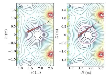
Fig.1. The HL-2M equilibrium,and the electron cyclotron wave trajectories on a poloidal plane.The pink line in(a)and(b)are the contours of the helical flux surfaces of(2,1)and(3,2)magnetic islands.
Figure 2 shows a radial profiles of ECW power deposition and driven current density with different poloidal injection angles of 120°and 128°. The power absorption and driven current in Fig. 2 corresponds to the wave trajectories in Fig. 1. It can be seen that the increment of the poloidal angle also increases the current drive efficiency to some extent. In both cases, the absorption of wave power is 100%.The ECCD efficiency(n(20)R(m)I(A)/P(W))in the two cases with poloidal angles of 120°and 128°is about 0.011 and 0.014×10²⁰A/W/m2, respectively. Since our focus here is on the suppression of NTM by ECCD,we will not give more calculation results of ECCD in the HL-2M configuration. One can refer to Ref.[35]for more detailed calculations. However,we could still make a summary: (i) Increasing the poloidal angle moves the wave deposition position to the plasma core;(ii) Both adjusting the toroidal angle (within a certain range)and increasing the plasma core temperature increase the current drive efficiency of the wave;(iii)Wave injected from the upper launcher port drives larger plasma current than midplane injection. Therefore, an upper launcher port has been designed for the ECW system in HL-2M.
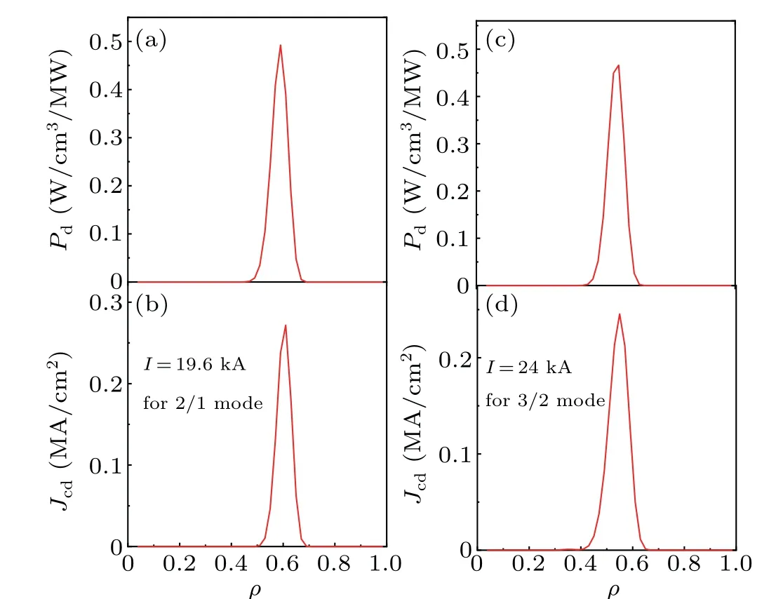
Fig. 2. Radial profile of ECW power deposition and driven current density with different poloidal injection angles 120° (a),(b)and 128° (c),(d).
3.2. Neoclassical tearing mode stabilization
Now we substitute the driven current calculated in the previous section into Eqs.(6)and(7)to simulate the process of NTM suppression. Table 1 shows the input parameters of the TM8 codes. It should be noted that the poloidal angles have been adjusted in order to guarantee that the current density is deposited on the rational surface,and thewcdin Table 1 is the half-width of current density profile.
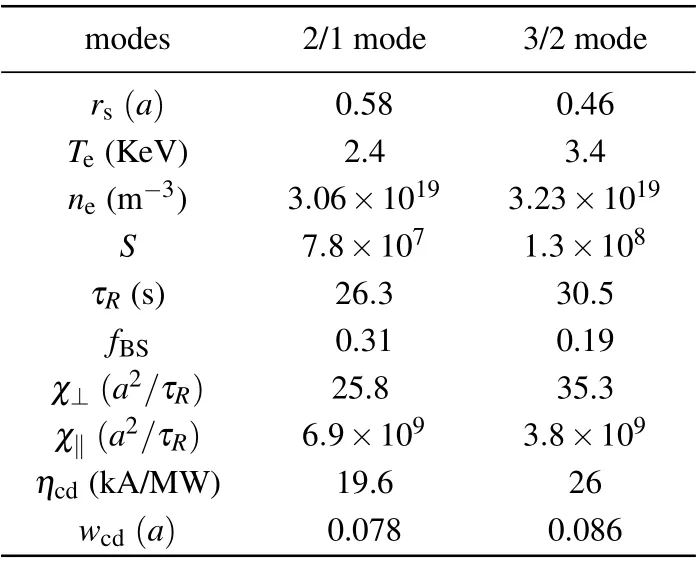
Table 1. Simulation parameters.
In order to study the stabilization of NTM, we first explore the influence of ECCD on NTM by changing the amplitudes of driven current. Figure 3 presents the evolution of the NTM magnetic island in different cases. The black line corresponds to the modulated ECCD cases with input wave powerP=3 MW, the red dotted line to the non-modulated ECCD case with input wave powerP=3.0 MW.In the modulated case, it indicates that 3MW ECW fully stabilizes the(2,1)NTM mode.Increasing the ECW power reduces the time needed for the complete suppress of NTM,while reducing the ECW power leads to the incomplete stabilization of NTM,and makes the magnetic island width saturated at a moderate value.On the other hand,the ECW power(3 MW)that is enough to control (2,1) NTM in modulated case cannot fully stabilize the NTM in the non-modulated case. Higher ECW power is needed for NTM suppression with NMCD. It is also worth pointing out that the saturation magnetic island width of the NTM in the simulation is 0.34awhen there is no ECCD.Compared with the magnetic island width in HL-2A(~0.14a),this value is larger,but it is reasonable because HL-2M is set to be highβplasma, and has a larger fraction of bootstrap current,and,therefore,the saturation width of magnetic island is relatively large.
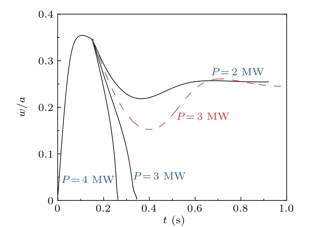
Fig.3. The evolution of the NTM magnetic island width in different cases:the black lines correspond to the modulated ECCD cases with different wave input power,the red dotted line to the non-modulated ECCD case with wave input power P=3.0 MW.
Figure 4 depicts the evolution of the(2,1)NTM magnetic island of lager characteristic widthwcdand during radial misalignment ECCD.It can be seen that when the radial deviation reaches a quarter of half-width of the current profile,the ECW power, that can completely stabilize the NTM in absence of deviation, no longer fully suppress the (2,1) NTM, but only reduces the saturation width of the magnetic island to a lower level.The value of this lower level is 0.05ain our calculations.In addition,increasing the half-width of the current profile also reduces the effect of NTM suppression. The 3 MW ECCD decreases the island width to 0.25aonly whenwcdis increased by 0.5 times. The NTM suppression effect is sensitive to the width of driven current profile. Our previous simulation with scanning of the poloidal injection angle indicates that a smaller poloidal injection angle corresponds to a larger ECCD characteristic width when the ECW wave is launched in the upper launch port. Therefore, ECW emission with a large poloidal injection angle is beneficial to NTM suppression.
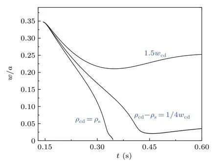
Fig. 4. The evolution of the (2,1) NTM magnetic island width with radial misalignment ECCD and lager characteristic width,wcd.
Figure 5 shows the evolution of the(3,2)NTM magnetic island in different ECW power level with both modulated and non-modulated ECCD.It is shown that after linear growth of(3, 2) NTM mode, the magnetic island width at saturation is 0.115awithout ECCD.2.5 MW ECCD completely suppresses NTM,and 1 MW ECW power only reduces the island width to its 1/4 in the MCD cases;3 MW ECW power quickly reduces the island width to zero. 2.5 MW of non-modulated current does not completely stabilize NTM,and only reduces the size of the magnetic island to its 3/4. More EC wave power input is needed in this case in order to fully suppress the magnetic island.
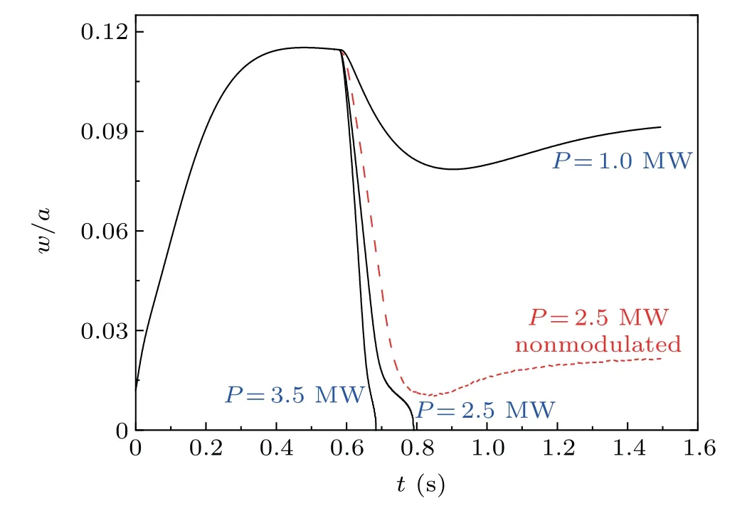
Fig.5. The same as in Fig.3,but for(3,2)NTM stabilization.
Figure 6 gives the same plot as in Fig. 4, but for (3,2)NTM,for which the influence of radial mismatch and current profile width on NTM suppression effect is similar to that of(2,1)mode. Increasing of the current profile width and radial deviation increase power threshold for complete suppression of NTM. However, the current profile width and radial deviation has weaker influence on the (3,2) mode suppression than they do on (2,1) mode. The 2.5 MW ECCD could still suppress the island width to 0.03awhenwcdis increased by 0.5 times, meaning that the ECCD reduces the magnetic island width by 3/4 in such a case. Figure 6 also indicates that(2,1)mode is more difficult to be suppressed than(3,2)mode,and has a greater deleterious impact on plasma performance improvement, which is consistent with the results from La Haye.[36]It is also should be noted that our simulation considers the NTM with neoclassical effect,because if the bootstrap current is not considered, the magnetic island saturation will be lower than the magnetic island saturation level presently here. Especially for the (3,2) mode, if the neoclassical effect of the bootstrap current is not incorporated, the tearing mode will not be excited.
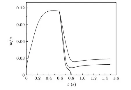
Fig.6. The same as in Fig.4,but for(3,2)NTM control.
3.3. Time needed to suppress the neoclassical tearing mode
Now we come to study the time needed to suppress both the (3,2) and (2,1) mode systematically. Figure 7 shows the time necessary to reduce the island to 1/3 of its initial size(solid line)and for complete stabilization(dashed line)versus ECW power, for both the (3,2) mode (a) and the (2,1) mode(b). It demonstrates that the time required for suppression of(3,2) mode is shorter than that for (2,1) mode. The time required to completely suppress(2,1)mode is about 0.2 s,while it is 0.128 s that required to suppress (3,2) mode when the power is 3.0 MW.Overall,the time for suppress of(3,2)mode shorter.This is reasonable since the bootstrap current is significantly larger at theq=2/1 than that at theq=3/2 surface,and thus the current to be replaced is larger and the power needed is larger as well. In other words, the time needed for(3,2)mode suppress should be shorter when input wave power are the same. On the other hand, when one reduces the magnetic island to 1/3 of the saturation value, similarly, the suppression time could also be shortened.
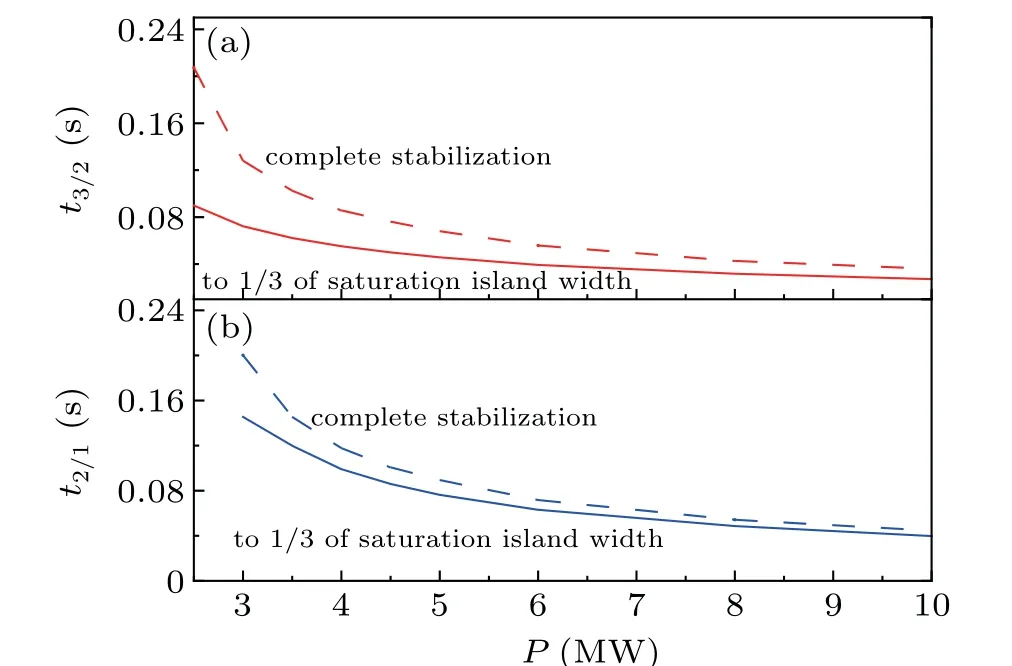
Fig.7. Time necessary to reduce the island to 1/3 of saturation island width value (solid line) and for complete stabilization (dashed line) versus ECW power,for both the(3,2)mode(a)and the(2,1)mode(b).
Time needed for complete stabilization versus initial island width (normalized to the saturation width) is shown in Fig. 8 for both the (2,1) and the (3,2) modes. It can be seen that the earlier the ECCD is placed,the shorter the time needed to fully suppress NTM.The relationship between the required time andwiniis linear for (3,2) mode, while there is also a weak linear relationship for(2,1)mode. What should be noted is that the input power in Fig.8 is 5 MW.One can still see that the time for suppression of(3,2)mode is shorter than the that for(2,1)mode. The time required for suppression of the two is very close when the initial magnetic island is small. This result seems similar to the simulation result in ITER.[37]
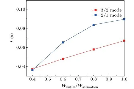
Fig. 8. Time needed for complete stabilization versus ECW initial island width(the island width when ECW power is added,normalized to the saturation width),for both the(2,1)and the(3,2)modes.
4. Conclusion
Investigation of neoclassical tearing mode and its suppression by electron cyclotron current drive (ECCD) have been performed for HL-2M tokamak. The electron cyclotron wave driven current capability is evaluated. It is found that the deposition location can be effectively controlled by changing poloidal injection angle. The validation of electron cyclotron wave heating and current drive has been demonstrated for the upper launcher port. The required poloidal injection angle range is about 30°(from 98°to 128°)in order to cover the radial range ofρ=0.5-0.9. The absorption of the wave power reaches 100%,while current drive efficiencies reach the order of 0.014×10²⁰A/W/m2with the upper launcher emission.
For the NTM suppression, we show that 3.0 MW and 2.5 MW modulated ECCD can completely stabilize(2,1)and(3,2) NTMs, respectively. The non-modulated ECCD, radial misalignment as well as current profile broadening have deleterious effect on the NTM stabilization. The time required for suppression of(3,2)mode is shorter than that required for the suppression of(2,1)mode. We find that the earlier the ECCD is placed,the shorter the time needed to fully suppress NTM.And the relationship between the required time andwiniis basically linear.
In general, the total electron cyclotron wave current of 5 MW is sufficient to have a full stabilization of both (2,1)and(3,2)modes. In addition,the plasma temperature we set is lower than the expected when calculating the ECCD.From the current expected parameters,the plasma center temperature of HL-2M will be higher than 6 keV.Increasing the temperature will significant increase the current drive efficiency. Therefore,our simulation here gives a conservative EC wave power input for full suppression of(2,1)and(3,2)modes. Up to 30%higher CD efficiencies are predicted if the plasma has a core temperature of 10 keV,at the cost of higher ohmic heating and other auxiliary heating.
Acknowledgments
The authors would like to thank X. Wang at HIT, Min Xu at SWIP,Q.Yu, X.Wang, and L.Xue for fruitful discussions. J. C. Li also thanks the High-performance Computing Platform of Peking University.
猜你喜欢
杂志排行

Chinese Physics B的其它文章
- Projective representation of D6 group in twisted bilayer graphene*
- Bilayer twisting as a mean to isolate connected flat bands in a kagome lattice through Wigner crystallization*
- Magnon bands in twisted bilayer honeycomb quantum magnets*
- Faraday rotations,ellipticity,and circular dichroism in magneto-optical spectrum of moir´e superlattices*
- Nonlocal advantage of quantum coherence and entanglement of two spins under intrinsic decoherence*
- Universal quantum control based on parametric modulation in superconducting circuits*