Effect of Supported Bearing Clearance on Load-Sharing Characteristics of a Double-Row Planetary Gear System
2021-06-22WANGLinfeng王林峰LIUJing
WANG Linfeng(王林峰), LIU Jing(刘 静)
1 College of Mechanical and Vehicle Engineering, Chongqing University, Chongqing 400044, China
2 School of Marine Science and Technology, Northwestern Polytechnical University, Xi’an 710072, China
Abstract: Few studies were focused on the load-sharing characteristics of double-row planetary gear (DRPG) systems with bearings. Meanwhile, the supported bearing has an important influence on the transmission characteristics of the entire system. To overcome this problem, a multi-body dynamic (MBD) model of the DRPG system fully considering the influences of bearing parameters is established. Dynamic loads among contacting gear pairs have been obtained to calculate the load-sharing coefficient (LSC) of the system. The LSC of each gear tooth pair has been compared to study the effect of the supported bearing clearance on the load-sharing characteristics. These methods are based on Hertz contact theory. The liner stiffness and damping are used in the model. The results show that the supported bearing clearance has a greatly effect on the LSC of the DRPG system. Choosing appropriate clearance parameters of supported bearing can help suppress the uneven load distribution of the DRPG system. The results can provide some guidance to find new method to study the LSC and increase the service life of planetary gear systems.
Key words: double-row planetary gear (DRPG) system; supported bearing clearance; load-sharing coefficient (LSC); multi-body dynamic (MBD)
Introduction
Double-row planetary gear (DRPG) systems can achieve heavy load and high transmission ratios. They are widely used in special vehicles and other large heavy-duty mechanical equipment. The load-sharing characteristics of DRPG systems have a great effect on the system working performance. Many scholars have found that the internal factors, such as bearing parameters, tooth shape parameters and comprehensive transmission errors have an important influence on the load distributions of planetary gear (PG) system by studying the single-row PG system. However, the effect of supported bearing on the load-sharing coefficient (LSC) of the PG system is often ignored. It has an important influence on the LSC of the entire system. When the supported bearing clearance is unreasonable, the LSC of the PG system will be significantly reduced, and the vibration shock of the PG system may be significantly enhanced. The large vibration impact could decrease the service life of a transmission system and delay the progress of mechanical work. More seriously, it may endanger the life of operators and cause serious accidents. Therefore, a clear understanding of excitation effects of supported bearing clearance in the LSC of the PG system is meaningful. It can provide a useful method of controlling mechanical vibration and extending the mechanical service life. In practical engineering, it is difficult to analyze the influence of a certain factor on the load distributions of a PG system. Theoretical modeling can provide ways for finding key factors and optimization methods that affect the LSC of the PG system.
Many scholars had done a lot of work in dynamic modelling and load sharing analysis of PG systems. For example, Singh[1]presented a gear system analysis module (GSAM) to study the effect of carrier pin-hole position errors on the quasi-static load-sharing between pinions. Singhetal.[2]studied the influence of certain key factors in a PG system by presenting comprehensive experimental and theoretical analyses. Ligata and Kahraman[3]studied the effect of manufacturing errors on the load distribution and stresses of a PG system. Luetal.[4]established a dynamics model of a PG transmission system and analyzed the dynamic load-sharing characteristics of a system under the excitation of sun gear floating, various installation errors and input speeds. Based on a physical explanation, Singh[5]established an epicyclic load-sharing map of load-sharing behaviors in a PG system. Lietal.[6]studied dynamic model of three-degree-of-freedom spur gears including the bearing clearance and backlash. This work obtained the process of system chaos formation. Wuetal.[7]established a nonlinear dynamic model based on the Ravigneaux compound PG system to analyze the effect of installation errors and eccentricity errors on load-sharing characteristics of the system. Yangetal.[8]proposed a translation-torsion dynamic model of a compound PG with multi-factor exciting and compared the effects of each excitation on the load-sharing characteristics. Liuetal.[9]proposed a finite element (FE) PG system method with a localized fault in the planet bearing and analyzed the dynamic characteristics. Parkeretal.[10]established a model of a PG system to analyze the rotational and translation in different output cases. Kahraman[11]established a multi-body dynamic (MBD) model for analyzing kinetic characteristics of a simple PG system. Weietal.[12]published a new approach to analyze the kinetic characteristics of a PG model. Mohammadpouretal.[13]proposed a tribo-dynamic planetary system model to study the transmission efficiency and the transmission noise. Researchers[14-18]proposed a few meaningful study methods and kinetic models to analyze the vibrations of various roller bearings. Most researchers studied the load distribution of single-row PG systems[1-6, 11-12]. Although some scholars studied the load distribution of compound PG systems[7-8], they mainly focused on the effects of load torque, dimensional parameters of PG and installation errors. Few researchers have analyzed the load distribution of compound PG systems based on the effect of bearing parameters. An MBD model of compound PG systems with the bearing parameters (such as clearance, stiffness and damping) has been established. The coupled excitation of the load torque and the input speed is also considered. It is significant to improve the modeling accuracy of PG systems.
Many researchers have studied the LSC of the single-row PG system. But few papers are presented to analyze the effect of the supported bearing clearance on the dynamic LSC of a DRPG system. In practice, the structure of a single-row PG system is very different from that of the DRPG system as shown in Fig. 1.
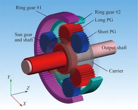
Fig. 1 MBD model of DRPG system
In order to analyze the load-sharing characteristics of the DRPG system with the influence of the clearance of bearings, an MBD model of DRPG systems is established in the paper. As shown in Fig. 1, the system includes six planet bearings, one carrier, and two ring gears. The bearing installing positions of the DRPG system are shown in Fig. 2. The supported bearings are roller bearings. S1 and S2 represent two types of supported bearings, respectively. P1 represents a planet bearing and it is a ball bearing. The axial clearance of the roller bearing is indicated by the symbolSa. The radial clearance of the ball bearing is indicated by the symbolSr.The meshing stiffness and the damping between the gears are obtained by the current methods in Refs. [14-18], as well as the contact stiffness and the damping in the bearings. The current methods are based on Hertz contact theory which has been used in this model to calculate the meshing stiffness of the meshing teeth. Viscous damping theory is used in this model which assumes that the damping force is proportional to the relative tooth velocity normal to the surfaces. To simplify the model, the stiffness and the damping are considered to be linear. The supported bearing clearance is considered into the deformation of each bearing roller. The load distributions are analyzed by calculating dynamic equations of the system.
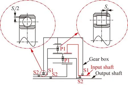
Fig. 2 Schematic diagram of DRPG system with bearing installation positions
1 Problem Description
The MBD model of a DRPG system established in this paper is a key transmission part of special vehicles. Without a clear understanding of excitation mechanism of internal parameters, premature failure of the system would never be handled. Bearing clearance is one of the key components affecting the transmission characteristics of the system. At high speed and under heavy load conditions, even a small clearance size error of a bearing may cause large unbalance load distribution and significant vibration. Therefore, this paper aims to analyze the effect of bearing clearances on the DRPG system.
The schematic diagram of a DRPG system with bearing installation positions are displayed in Fig. 2. Position relationships and rotation directions of DRPG system components are displayed in Fig. 3. As shown in Fig. 1 and Fig. 3, there are two ring gears (ring gear #1 and ring gear #2), three long PGs (A1, A2 and A3) and three short PGs (B1, B2 and B3) in the MBD model. The ring gear #1 is fixed on the gearbox and meshed with the short PG (B1, B2 and B3). The input shaft with a constant velocity is connected with the ring gear #2, which is shown in Fig. 1. Long PGs (A1, A2 and A3) are meshed with the short PGs (B1, B2 and B3), respectively. The carrier is fixed with the output shaft and meshes with long PGs. All PGs (A1, A2, A3, B1, B2 and B3) are connected by six cylindrical roller bearings (P1), respectively. The carrier is supported by the sun gear and connected with long PGs. There are two types of ball bearings S1 and S2 working as the supported bearings. Installation positions and connection relationships of support bearings has been shown in Fig. 2. The ring gear #2 has a constant speed input. The sun gear, the planetary cage, and all planet gears can rotate freely around the axis. The rotational freedom inZdirection of the ring gear #1 is suppressed. It can make the DRPG system reach a stable transmission ratio. The sun gear, the ring gear #1 and PGs are floating inXandYdirections. The contact position of meshing tooth is obvious randomness. There is no obvious periodicity for the gear meshing force. Note that this paper mainly analyzes the LSC of the DRPG system with the influence of supported bearing clearance.
2 Calculation Method of LSC
The MBD model of the DRPG system in this paper is established by the Simpack software. The gear numbers of the system are shown in Fig. 3. Define the tooth meshing force of the ring gear #2 and long PGs (A1, A2 and A3) during a meshing cycle aspo2ah(h=1, 2, 3). Define the tooth meshing force of the sun gear and long PGs (A1, A2 and A3) during a meshing cycle aspsah, Define the tooth meshing force of the ring gear #1 and short PGs (B1,B2 and B3) during a meshing cycle aspo1bh. The LSC of the meshing tooth force in any meshing cycle can be expressed as

Fig. 3 Position relationships and rotation directions of DRPG system components
(1)
whereNrepresents the number of PG groups;pjhrepresents the tooth meshing force in the PG system; the subscriptjhis used to distinguish the meshing relationship of different positions,j=o2a, sa, o1b;h=1, 2, 3 (note that whenj=sa andh=1,pjhrepresents the tooth meshing force between sun gear and long PG A1). In this model, PGs (A1, A2 and A3) form three sets of PGs separately from PGs B1, B2 and B3, respectively. The parameterNis 3 in this DRPG system. By connecting the LSC of a period into a curve, the LSC change of the PG system during this period can be obtained. The LSC in a motion cycle is given as
Bj=|Mjh-1|max+1,
(2)
whereMjhis a sequence curve ofmjh;Bjis the LSC of the entire PG system transmission in the system cycle. More details for variables in above equations are listed in Ref.[7].
3 Results and Discussion
The MBD model of the DRPG system has been established by a lumped parameter method. The rotation directions of components in the DRPG system are shown in Fig. 3.ωA,ωB, andωRrepresent the angular velocity of long PGs, short PGs and the ring gear #1, respectively. In order to avoid the influence of the PG phase on the PG train load factor, the phase difference between each two long PGs is 120°, as well as each two short PGs[19-20]. The parameters of the MBD model of the DRPG system has been listed in Table 1. Full parametric method has been implied to establish this MBD model of the DRPG system. Based on Hertz contact theory, the rigid contact is considered between the gears in this model. For more precise analyses, the standard [DIN 3990 Method] is chosen as the tooth stiffness method. Note that [DIN 3990 Method] is the West German Industrial Standard for calculation of load capacity of the cylindrical gears and bevel gears. The friction force is based on the Coulomb friction method. The parameters of supported bearings and planetary bearings are listed in Table 2. The damping coefficient of a bearing is equal to the contact stiffness multiplied by a coefficient (0.025×10⁻⁵- 2.500×10⁻⁵)[21]. The bearing installation positions are shown in Fig. 2. The damping transition type is considered as a linear one.Sais 30 μm.Sris set as 10, 20, 30, 40, and 50 μm, respectively.
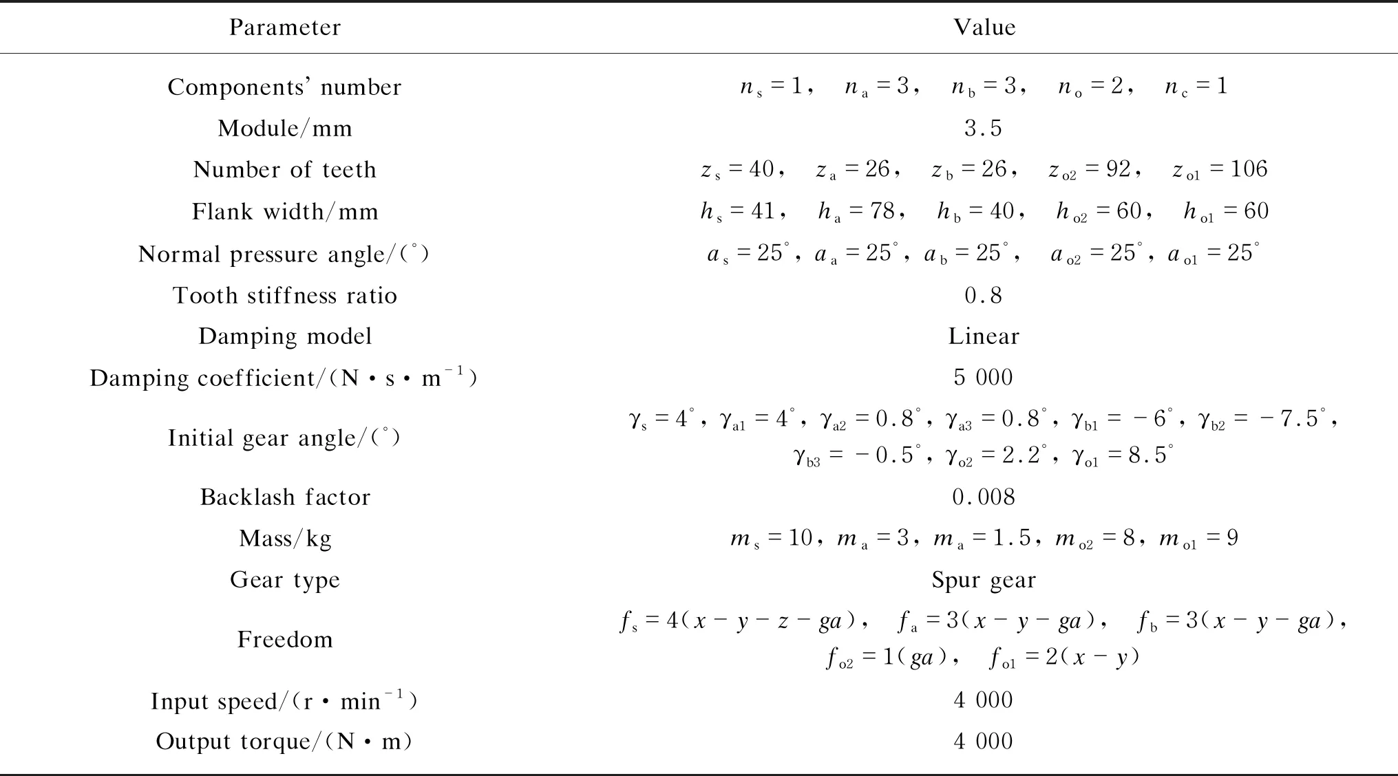
Table 1 Parameters of MBD model of DRPG system

Table 2 Bearing parameters of MBD model of DRPG system
The input shaft rotates at a speed of 4 000 r/min. The torque applied on the output shaft is 4 000 N·m. In order to study the influence of supported bearing clearance on the load-sharing characteristics,Srof supported bearings of the input shaft and the output shaft (S1 and S2 shown in Fig. 2) is set to 10, 20, 30, 40, and 50 μm, respectively. The LSCs of the DRPG system are obtained. The influence of supported bearing clearance on the LSC is analyzed. The LSC curves between the ring gear #2 and PG (A1, A2 and A3) are termed asMo2a1,Mo2a2andMo2a3curves, respectively. The LSC curves between the sun gear and long PGs (A1, A2 and A3) are termed asMsa1,Msa2andMsa3curves, respectively. The LSC curves between the ring gear #1 and short PGs (B1, B2, and B3) are termed asMo1b1,Mo1b2andMo1b3curves, respectively. The sun gear, the ring gear #1 and PGs are floating inXandYdirections as shown in Fig. 3. The contact position of the meshing tooth is obvious randomness. There is no obvious periodicity for gear meshing force.
LSC curves shown in Figs. 4-9 are aimed to compare and extract the maximum load factor. Figure 4 introduces the LSC curves ofMo2ah,Msah, andMo1bhwhen the supported bearing clearanceSris 10 μm. The LSC fluctuates greatly with the meshing cycle number. In Fig. 4(a), the maximum LSC between the ring gear #2 and long PGs is 2.021. The fluctuation of theMo2a1curve is the most obvious. In Fig. 4(b), the maximum LSC between the sun gear and long PGs is 1.788. The fluctuation of theMsa3curve is the most obvious. In Fig. 4(c), the maximum LSC between the ring gear #1 and short PGs is 1.937. The fluctuations ofMo1b1andMo1b3are more obvious than those ofMo1b2.
Figure 5 introduces the LSC curves ofMo2ah,Msah, andMo1bhwhenSris 20 μm. The LSC fluctuates greatly with the meshing cycle number. In Fig. 5(a), the maximum LSC between the ring gear #2 and long PGs is 1.711. The amplitudes ofMo2a1Mo2a2andMo2a3curves are relatively close. In Fig. 5(b), the maximum LSC between the sun gear and long PGs is 1.700. The fluctuation of theMsa3curve is the most obvious comparing with that of other two curves. In Fig. 5(c), the maximum LSC between the ring gear #1 and short PGs is 3.396. The fluctuation of theMo1b2curve is significantly higher than that of other two curves.

(a)

(a)
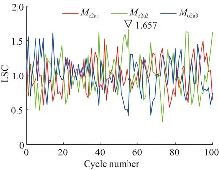
Figure 6 introduces the LSC curves ofMo2ah,Msah, andMo1bhwhenSris 30 μm. The LSCs fluctuate greatly with the meshing cycle number. In Fig. 6(a), the maximum LSC between the ring gear #2 and long PGs is 1.657. The amplitudes ofMo2a1Mo2a2, andMo2a3curves are relatively close. In Fig. 6(b), the maximum LSC between the sun gear and long PGs is 1.835. The fluctuation ofMsa3curve is the most obvious. In Fig. 6(c), the maximum LSC value of ring gear #1 and short PGs is 2.123. The fluctuations ofMo1b2andMo1b3curves are slightly higher than those ofMo1b1.
Figure 7 introduces the LSC curves ofMo2ah,Msah, andMo1bhwhenSris 40 μm. The LSCs fluctuate greatly with the meshing cycle number. In Fig. 7(a), the maximum LSC between the ring gear #2 and long PGs is 1.752. The amplitudes ofMo2a1Mo2a2, andMo2a3curves are relatively close. In Fig. 7(b), the maximum LSC between the sun gear and long PGs is 2.401. The fluctuations ofMsa1andMsa3curves are more obvious than those ofMsa2curve. In Fig. 7(c), the maximum LSC between the ring gear #1 and short PGs is 2.716. The fluctuations ofMo1b2andMo1b3curves are slightly higher than those ofMo1b1curve.
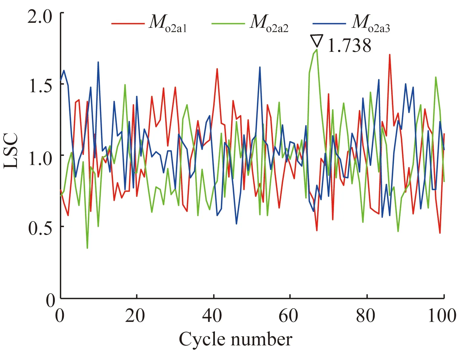
Figure 8 shows the LSC curves ofMo2ah,Msah, andMo1bhwhenSris 50 μm. The LSCs fluctuate greatly with the meshing cycle number. In Fig. 8(a), the maximum LSC value between the ring gear #2 and long PGs is 1.738. The fluctuation of theMo2a2curve is slightly higher than that of other two curves. In Fig. 8(b), the maximum LSC between the sun gear and long PGs is 2.303. The fluctuations of theMsa3curve is the most obvious comparing with those of other two curves. In Fig. 8(c), the maximum LSC between the ring gear #1 and short PGs is 2.597. The fluctuations ofMo1b2andMo1b3curves are slightly higher than those of theMo1b1curve.
(a)

(a)
(a)
Figure 9 introduces the LSC curves ofMo2a1,Msa1, andMo1b1with different supported bearing clearances. The LSCs fluctuate greatly with the meshing cycle number. In Fig. 9(a), the maximum LSC of theMo2a1curve is 2.021 whenSris 10 μm. In Fig. 9(b), the maximum LSC of theMsa1curve is 2.135 whenSris 40 μm. The fluctuation ofSrequaling 40 μm is the most obvious comparing with that of other curves. In Fig. 9(c), the maximum LSC of theMo1b1curve is 2.499. The fluctuation ofSrequaling 20 μm is slightly higher than that of other curves.
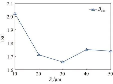
Figure 10 shows the influence ofSron LSC.Bj(j= o2a, sa and o1b) is the LSC of the entire system.Bo2ais the maximum LSC ofMo2a1,Mo2a2andMo2a3curves in all statistical cycles.Bsais the maximum LSC ofMsa1,Msa2, andMsa3curves in all statistical cycles.Bo1bis the maximum LSC ofMo1b1,Mo1b2, andMo1b3curves in all statistical cycles. The LSCs fluctuate greatly with the increment ofSr. In Fig. 10(a),Bo2afluctuates withSrand the maximum value is observed whenSris 10 μm. With the increment ofSr,Bo2atends to decrease. WhenSris 30 μm, the minimum value is observed. In Fig. 10(b),Bo2afluctuates withSrand the maximum value is observed whenSris 40 μm. With the increment ofSr,Bo2atends to decrease. WhenSris 20 μm, the minimum value is observed. In Fig. 10(c),Bo2afluctuates with differentSrand the maximum value is observed whenSris 20 μm. WhenSris 10 μm,Bo1breaches the minimum value. Some clearance conditions of supported bearing causing a serious uneven load distribution need to be prevented. Choosing appropriate clearance parameters of supported bearing can help suppress the uneven load distribution of the DRPG system.

(a)
(a)
4 Conclusions
An MBD model of the DRPG system is established in the paper. The influences of supported bearing clearanceSrunder constant input speeds and torque on the PG system are analyzed. This study can provide a good direction for future research on the load distribution features of the PG system to suppress the unbalance load distribution and improve the PG dynamics.
The supported bearing clearance has a great influence on the LSC of the DRPG system. When the supported bearing clearance is constant, three meshing forces at the same position have different load distributions. The three LSCs of meshing forces are significantly different with each other. There are no obvious linear relationships between the LSC and supported bearing clearance of the DRPG system. When the supported bearing clearance is in a certain range, the LSC can be reduced significantly. Therefore, a reasonable supported bearing clearance can reduce the uneven load distribution effectively. Some clearance conditions of supported bearing causing serious uneven load distribution need to be prevented.
杂志排行

Journal of Donghua University(English Edition)的其它文章
- Electrochemical Performance of Core-Sheath Dip-Coated Lignin Derived Carbon/Wet-Spun Graphene Electrodes for Fiber-Shaped Supercapacitors
- Preparation and Properties of Polyurethane/Nickel Nanofiber with Core-Shell Structure Using Coaxial Electrospinning Method
- Trajectory Optimization and Motion Simulation of a Flexible Polishing Industrial Robot for Watchcases
- Meta-Analysis on the associations between Prenatal Perfluoroalkyl Substances Exposure and Adverse Birth Outcomes
- Numerical Simulation of Space Fractional Order Schnakenberg Model
- Symmetry Classification of Partial Differential Equations Based on Wu’s Method