Two-dimensional PC3 as a promising anode material for potassium-ion batteries: First–principles calculations*
2021-05-24ChunZhou周淳JunchaoHuang黄俊超andXiangmeiDuan段香梅
Chun Zhou(周淳), Junchao Huang(黄俊超), and Xiangmei Duan(段香梅)
School of Physical Science and Technology,Ningbo University,Ningbo 315211,China
Keywords: two-dimensional materials,potassium-ion batteries,first-principles
1. Introduction
In recent years, with the rapid development of the electronic market, the demand for innovative batteries with excellent performance has been increasing. So far, lithium-ion batteries(LIBs)are the most widely used batteries,with high power density, great charge–discharge efficiency, and long life cycle. However, the lithium resources on the earth are limited and its stocks are falling, which poses a challenge to the development of LIBs. With the growing interest in LIBs alternatives, it is urgent to find suitable new electrode materials.[1]Since the outer electronic structure and electrical properties are similar to LIBs,sodium-ion batteries(SIBs)and potassium-ion batteries(PIBs)have been proposed to resolve this crisis. Compared with LIBs, they have the advantages of low cost, high safety, and abundant reserves on the earth.Meanwhile, the mature theoretical knowledge and technical experience of LIBs can be applied to SIBs and PIBs to a certain extent. Compared with SIBs, LIBs have higher voltage and energy density due to lower standard electrode potential.However,the standard electrode potential of K+/K is comparable to, or even lower than, that of Li+/Li, which indicates that PIBs have higher voltage and energy density.[2]Taking these factors into consideration,we regard PIBs as a more appropriate choice. However,the lack of suitable anode materials hindered the development of PIBs.
Since the successful exfoliation of graphene in 2004,two-dimensional(2D)materials have received widespread attention due to their excellent physical and chemical properties. As anode materials of ion batteries, 2D materials have also shown outstanding performance. For instance, graphene nanosheet families exhibit excellent behavior in rechargeable LIBs.[3]Phosphorene has attracted much attention due to its remarkably high theoretical capacity (2596 mAh·g−1) in SIBs.[4]Phosphorene and graphene heterostructure have also been investigated as the anode for LIBs.[5]However,these materials are not suitable for PIBs,partly because potassium has a larger atomic radius. Several 2D materials have been proposed as anode for PIBs, such as FeSe2,[6]GeSe,[7]YN2,[8]and T-NiSe2.[9]However, as an emerging novel ion battery,PIBs choice is far from enough. Therefore, it is necessary to explore high-performance anode materials for PIBs.
It has been reported that metallic P3C and PC3monolayer can be used as anode for SIBs,and 2D PC6sheet is a promising anode material for PIBs.[10–12]Due to the excellent conductivity and stability of the material composed of C elements and the high specific capacity of P-based materials, we focus on the 2D binary materials of P and C. Similarly, 2D binary materials g-SiC2and g-SiC3have been used as anode materials for LIBs. And they have shown excellent performance by combining the good qualities of both elements Si and C.[13]After a series of screening and testing, we finally choose the PC3monolayer, which is a stable hexagonal structure similar to graphene, with high theoretical capacity and low voltage,and is very suitable to be anode material for PIBs.
2. Computational method
All calculations are performed using density functional theory (DFT) as implemented in the Vienna ab initio simulation package (VASP).[14,15]The Perdew–Burke–Ernzerhof(PBE) functional of the generalized gradient approximation (GGA) is used to describe the exchange–correlation interactions.[16]The Brillouin zones are sampled using a 3×3×1 k-point grid according to the Monkhorste–Pack scheme for a 2×2 supercell.[17]The kinetic energy cutoff of 700 eV is used for all calculations. To avoid periodic image interactions,a vacuum space of 20 ˚A is set along the z direction to the PC3monolayer. The projector augmented wave (PAW) method is adopted to describe interactions among ion cores and valence electrons.[18]The DFT-D3 method for van der Waals interaction description is adopted.[19]All the structures are thoroughly relaxed until the forces are less than 10−2eV/˚A, and the energy convergence is below 10−5eV between two consecutive self-consistent steps. The migration pathways and diffusion barriers for K atoms on the PC3monolayer are calculated using the climbing image nudged elastic band(CI-NEB)method. To verify the stability of PC3monolayer, ab initio molecular dynamics (AIMD) simulations using a statistical ensemble with a fixed particle number, volume, and temperature (NVT) are performed at room temperature (300 K) for 5 ps with a time step of 1 fs.
3. Results and discussion
3.1. Structure and stability of PC3
A rationally designed 2D material PC3has a graphene–like hexagonal structure, and each unit cell contains six carbon atoms and two phosphorus atoms. It can be seen from the side view in Fig.1(a),adjacent phosphorus atoms are distributed on different sides, making PC3a buckled material with an up–and–down thickness of 1.19 ˚A.The optimized lattice parameters of the PC3monolayer are a = b = 5.42 ˚A,α =β =90°and γ =120°. The average C–C bond length is 1.42 ˚A,the same as in graphene,and the average P–C bond length is 1.81 ˚A, comparable to the values of 1.80–1.83 ˚A in phosphorus carbide.[20]
To verify PC3monolayer can be synthesized experimentally, we calculate its cohesive energy, Ecoh, which is defined as

where EC,EP,and ECP3are the energy of the isolated C atom,P atom,and PC3unit cell,respectively. The value of the cohesive energy is 6.41 eV,which is much higher than that of phosphorene (3.45 eV) and closer to that of graphene (7.98 eV).Such a high cohesive energy indicates that the structure of PC3is stable and could be synthesized. We use AIMD simulation to study the thermal stability of the PC3monolayer at room temperature. And after 5 ps, no structural deformation or bond fracture occurs,proving its high thermal stability[see Fig.1(b)].
Now, we calculate the electron local density along the plane of monolayer PC3to find the essence of its chemical bonding by using the electron localization function.[21]In Fig.1(c),the red region between C–C and C–P represents the strong covalent bond. Consistently, the Bader charge analysis shows that each P atom transferred 1.5|e|to the bonded C atoms,which is attributed to the fact that the electronegativity of C(2.55)is larger than that of P(2.19). It can be seen from Fig.1(d),PC3is an indirect band gap semiconductor(the gap is 0.75 eV). The valence band maximum is located at the M point,and the conduction band minimum is at the Γ point.
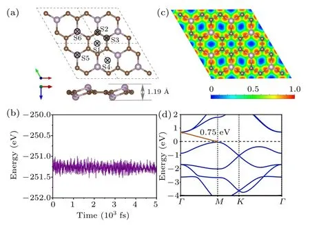
Fig.1.(a)The top and side view of optimized atomic configurations for PC3 and different adsorption sites for K ions. (b)The AIMD simulation of PC3 at 300 K for 5 ps. (c)Localization charge density and(d)band structure of PC3 monolayer.
3.2. Adsorption and diffusion of K atoms on PC3
The preference for K adsorption is characterized by the adsorption energy,Ead. The lower the energy,the more stable the adsorption configuration. For the K atom on PC3monolayer, there are six possible adsorption sites, as marked in Fig.1(a). The adsorption energy is defined as
where EK@PC3and EPC3are the total energy of the K-adsorbed and pristine PC3monolayers,respectively. And EKis the energy per atom in bulk K.After the optimization,S1,above the center of the C6 ring,has the largest Eadof −0.83 eV.The second stable site is S6,which is on the top of the hollow P atom,with an adsorption energy of −0.79 eV.In contrast to S6, S5 is on the top of the protruding P atom, Eadis −0.74 eV. The vertical distances between the K atom and the PC3plane are 2.54 ˚A,2.66 ˚A,and 2.53 ˚A at S1,S5,and S6 sites.We then focus on the most stable site S1 to study the electrical properties and diffusion barriers.
The charge density difference of K adsorbed PC3is shown in Fig. 2(a), where charge accumulates on the surface of PC3,while charge deletion is around the K atom,indicating that the charge is transferred from the K atom to PC3. The charge transferring can be understood by the fact that the electronegativity of C (2.55) is significantly larger than that of K (0.82). The Bader charge analysis manifests that 0.87 |e|transfers from the K atom to the substrate. For other K atoms adsorbed on S5 and S6 sites,the transferred electron is 0.88|e|.Upon potassium adsorption,the system becomes metallic,and the density of states (DOS) is shown in Fig. 2(b). The DOS at the Fermi level is greatly enhanced, and the contribution mainly comes from the substrate PC3, suggesting that more carriers are generated in the system. Therefore,the electronic conduction becomes better,which is beneficial for PIBs.

Fig. 2. (a) Charge density difference and (b) band structure of the Kadsorbed PC3. The yellow and blue regions represent charge accumulation and depletion,respectively. The isosurface level is set to 0.005 e·˚A−3.
The diffusion rate is a critical parameter for ion batteries. It is partly determined by the adsorption energy between the K atoms and the substrate. On the other hand, the diffusion rate of K atoms on the surface of the anode affects the performance and efficiency of the charging/discharging process to a great extent. To obtain the diffusion energy barrier of the potassium, we consider two possible diffusion pathways for the K atom (denoted as path I and path II) on PC3,as shown in Fig. 3(a). Via path I, the potassium goes from site S1 to the neighboring S1 directly, across the P2C4ring.Along path II, K moves zigzag from S1 to S6, then to the adjacent S1. The energy barriers via path I and path II are 0.92 eV and 0.16 eV,respectively. Note the energy barrier of 0.16 eV is significantly smaller than the Li diffusion barriers for pristine graphene(~0.28 eV),graphene with a point defect(~0.366 eV to 0.538 eV),[22]and graphite (~0.47 eV),[23]promising a fast K diffusion.
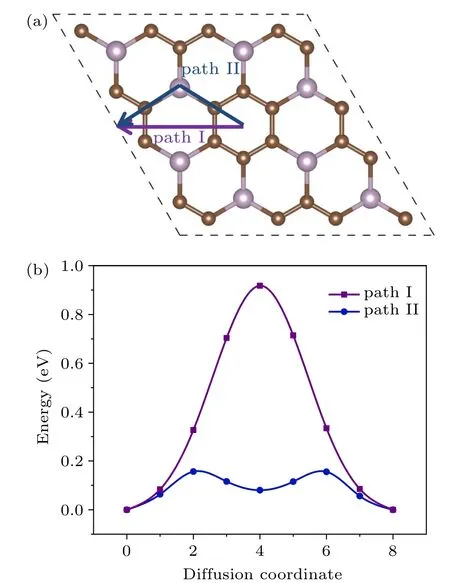
Fig.3. (a)The diffusion paths and(b)corresponding diffusion energy barriers of K atom transfer on PC3 surface.
3.3. Theoretical capacity and open-circuit voltage of PIBs with the anode of PC3
The performance of ion batteries strongly depends on the storage capacity of metal atoms on anode materials, which is directly related to the number of adsorbed metal atoms on the substrate. To this end,K atoms can be absorbed layer by layer on both surfaces of the PC3. The average adsorption energy of K atoms is obtained by

where n is the total number of adsorbed K atoms,EnK@PC3is the total energy of the K adsorbed PC3,and EPC3is the energy of pristine PC3. The negative adsorption energy indicates K atoms can be adsorbed stably.
Since K atoms have a tendency to form bulk spontaneously,we calculate the continuous adsorption energy of the additional layer Econby the formula

where L is the number of adsorbed layers, EKL/PC3and EK(L−1)/PC3are the total energy of L and L−1 layers K atoms adsorbed PC3,respectively.So Econshould always be negative to make sure it is favorable of loading extra K layer on PC3.
We load the first layer of K atoms at S1 on both sides of the substrate [see Fig. 4(a)]. After the optimization, all K atoms are steadily adsorbed.Eaveis calculated to be −0.50 eV,and the vertical distance between K atoms and the sheet is 2.64 ˚A.Since S1 sites are fully occupied by the first K layer,there are two possible positions for depositing the second K layer (PC3K2), namely S5 and S6 sites. It turns out that K atoms prefer to occupy the S5 sites [see Fig. 4(b)]. With adsorbing two potassium layers on both sides of PC3, Eavedecreases to −0.25 eV. The system remains energetically stable. To put the third K layer on,all the possible sites are considered, and S6 is the most favorable position; the optimized structure is shown in Fig.4(c). The average adsorption energy is −0.19 eV.When connected with the cathode,a weak binding with anode is desired to enhance the voltage.[1]For the fourth K layer,the value of layer-by-layer average adsorption energy is positive,indicating that the adsorption becomes energetically unfavorable. For L=3 to L=4,Econis −0.69 eV and 1.80 eV,respectively. Therefore,the limitation of loading K atoms is three layers on both sides,while the system maintains structural stability.The average adsorption energy ranges from −0.50 eV to −0.19 eV,which meets the requirement of ion batteries specifically.

Fig.4. Crystal structures of(a)PC3K1,(b)PC3K2,(c)PC3K3 from the side and top view. The violet balls indicate the K atoms. (d)Calculated OCV and theoretical capacity with different K adsorption concentrations.
Our electronic structural results show that,as the concentration of K atoms increases from one layer to three layers,the systems exhibit metallic characteristics and the subgaps below the Fermi level shrink. Correspondingly, the electronic conductivity of the PC3monolayer is enhanced with the increase of the concentration of K ions. The projected density of states(PDOS) is shown in Fig. 5; one can see the distinct overlap between the K-s orbital and the p orbitals of P and C at and around the Fermi level. Such significant s–p hybridization indicates notable interactions between potassium atoms and the PC3monolayer.
With the maximum K adsorption concentration on the PC3,we evaluate its storage capacity using the following equation:

Here x is the number of electrons transferred, F is the Faraday constant, and M is the molecular mass of PC3.[24]The storage capacity for the PC3monolayer is as large as 1200 mAh·g−1,significantly larger than that of the black phosphorus anode for PIBs (617–843 mAh·g−1),[25]and PC6in PIBs(781 mAh·g−1).[26]Such a high storage capacity can be attributed to the variety of adsorption sites on both sides and the light atomic weight of P and C.

Fig.5. Density of states for(a)PC3,(b)PC3K1,(c)PC3K2,and(d)PC3K3.The Fermi level is set to 0 eV and labeled with vertical dashed lines.

Another significant parameter of ion batteries is opencircuit voltage (OCV), which can characterize the performance of anode materials for PIBs. The average open-circuit voltage can be calculated by where c is the concentration of the adsorbed K atoms. The OCV decreases from 0.50 V, 0.25 V to 0.19 V with the increased number of adsorption layers. When the number of adsorbed K atoms reaches its limitation,we can obtain a fairly low OCV of 0.19 V.Such a low OCV can provide a large operating voltage with a higher energy density as applied in PIBs.Now we want to emphasize that the range of OCV is 0.19–0.50 V,which can avoid the formation of dendritic during the charge–discharge process.[27]This appropriate range of OCV values makes PC3an ideal candidate for anode material for PIBs.
4. Conclusion
By using first–principle calculations, we systematically investigate the structure stability and electronic property of the PC3monolayer,and find that the diffusion barrier of potassium on PC3is as low as 0.16 eV, ensuring the efficiency of the charging/discharging process. As an anode material, the PC3sheet has an ultra-high theoretical capacity of 1200 mAh·g−1,which could guarantee the long-term durability of the battery.The value of OCV is between 0.19 V and 0.5 V,which can ensure the safety of the charging/discharging process. With low diffusion barrier,high capacity,and suitable OCV,we predict that PC3is an ideal choice for PIBs anode materials.
杂志排行

Chinese Physics B的其它文章
- Corrosion behavior of high-level waste container materials Ti and Ti–Pd alloy under long-term gamma irradiation in Beishan groundwater*
- Degradation of β-Ga2O3 Schottky barrier diode under swift heavy ion irradiation*
- Influence of temperature and alloying elements on the threshold displacement energies in concentrated Ni–Fe–Cr alloys*
- Cathodic shift of onset potential on TiO2 nanorod arrays with significantly enhanced visible light photoactivity via nitrogen/cobalt co-implantation*
- Review on ionization and quenching mechanisms of Trichel pulse*
- Thermally induced band hybridization in bilayer-bilayer MoS2/WS2 heterostructure∗