Expansion performance and self-stressing behavior of CFST columns considering concrete creep and shrinkage effect
2021-04-24XuLiZengHaoPanJinlong
Xu Li Zeng Hao Pan Jinlong
(School of Civil Engineering, Southeast University, Nanjing 210096, China)
Abstract:Expansive concrete is used in the steel tube of Concrete-filled steel tubular (CFST) columns to solve the problem of steel-to-concrete debonding. Self-stress is generated between concrete and steel plate due to concrete expansion, which can effectively improve the mechanical performance of CFST columns. Deformation tests were conducted on concrete and CFST columns, respectively. The free deformation of concrete and circumferential deformation of steel tubes were measured and analyzed. A calculation method was proposed to evaluate the hoop strain, self-stress and creep deformation of the CFST columns. The test and calculation results indicate that the proper addition of expansion agent in the internal concrete can keep concrete expansive and generate self-stresses for a long time. The expansion and self-stresses prevent the debonding between the steel tube and the internal concrete. Increasing the dosage of expansive agents and reducing the curing age both increase the expansive deformation and self-stress of CFST columns. Increasing the tube thickness reduces the expansive deformation and increases the initial self-stress of CFST columns.
Key words:concrete-filled steel tubular (CFST); expansive deformation; self-stress; creep
Concrete-filled steel tubular (CFST) structures have been widely investigated and used in high-rise buildings and large-span structures due to their significant advantages, such as light weight, high load carrying capacity, excellent ductility and seismic performance[1-3]. The steel tube confines the lateral deformation of internal concrete and the concrete limits the buckling of steel tube when CFST is in compression[4]. Thus, strong interaction between concrete and steel tube should be kept for the excellent mechanical properties of CFST. In other words, the internal concrete should be close to the steel tube.
However, debonding commonly occurs between the steel tube and the internal concrete in CFST structures due to concrete creep, shrinkage and different Poissson’s ratios between the steel tube and concrete[5]. The debonding weakens the interaction of the two materials and reduces the load carrying capacity and ductility of CFST structures[6]. Thus, expansive concrete, obtained by introducing expansive agents into cement, is proposed to substitute ordinary concrete in steel tube[7-9]. The shrinkage is well compensated by the expansion, and close contact can be achieved between steel tube and concrete. Moreover, the concrete expansion can be restrained by the steel tube. Compressive stress is thus generated between the two materials, which is so-called self-stress[10].
Some studies were conducted to investigate the influence of the self-stress on the mechanical performance of CFST. The experiments in Ref.[11] found that an increase of 12.4% in load capacity was observed for the self-stressing CFST columns having a self-stress of 5 MPa. The improvement became more significant with the increase in the length-to-diameter ratio. The degree of increase in load capacity was also related to the initial self-stress, tube thickness and concrete strength[12]. Li et al.[13]tested 18 self-stressing CFST columns with different initial self-stresses, tube thicknesses, and concrete strengths under axial compression. The test found that the initial self-stress significantly increased the load capacity of CFST columns but reduced its deformability. However, the increase in the load capacity was negligible when the self-stress was low. Excessively high self-stress could adversely affect the load capacity, and the optimum self-stress level was 0.101.
Self-stress is crucial to the mechanical performance of CFST columns[10-13]. The self-stressing behavior must be acquired when designing the CFST structures. Most researchers calculated the self-stress by utilizing the strain of steel tube according to the third law of Newtonian mechanics[11]. The hoop strain and axial strain of steel tube were measured during tests, and this method was not feasible for engineering application. Some formulas were also proposed to calculate the self-stress of CFST according to elastic mechanics[14]. The formulas indicated that self-stress was directly related to concrete expansion. However, the expansive deformation varies over time due to concrete shrinkage and creep. The concrete creep in self-stressing CFST is greater than the creep of ordinary concrete due to the self-stresses[15]. Test results from Zhang et al.[16]found that the dosage of expansive agents and the stress ratio had significant effects on the creep strain of CFST. Thus, the creep development in the internal concrete may influence the expansive deformation significantly, and cause the loss of self-stress. Concrete creep should be considered when evaluating the self-stress of CFST. Nevertheless, the creep effect is not taken into account in these existing formulas.
Thus, this paper proposed a calculation method to study the expansion performance and self-stressing behavior of self-stressing CFST columns considering the effect of concrete creep and shrinkage. Deformation tests were conducted on concrete and CFST specimens, respectively. The calculation results were compared with the test results to validate the reliability of the calculation method.
1 Expansive Deformation Tests
1.1 Materials and mix design
Mix proportion tests were conducted to obtain the self-compacting and expansive concrete with good mechanical properties. Materials used in concrete included PⅡ42.5 Portland cement, fly ash (FA), sand, coarse aggregate, polycarboxylate-series superplasticizer (SP) and HME-IV concrete expansive agent (EA). EA contained primarily calcium oxide, calcium sulphoaluminate and gypsum. It substituted part of the cementitious materials in concrete to produce a certain volume expansion and eliminate the concrete shrinkage. Different dosages of EA were used in the mixture to study its influence on the mechanical and expansion performance of concrete. The detailed mix proportions are listed in Tab.1.

Tab.1 Mix proportion of concrete (weight ratio)
Slump tests, uniaxial compression tests, and elasticity modulus tests were conducted to evaluate the workability and mechanical properties of concrete. Cubic specimens with dimensions of 100 mm×100 mm×100 mm and rectangular specimens with dimensions of 100 mm×100 mm×300 mm were prepared and tested for compression tests and elasticity modulus tests, respectively. The corresponding results are shown in Tab.2. The slump extension and compressive strength of concrete decreased gradually with the increase in the dosage of EA. However, the elastic modulus of concrete exhibited no significant correlations with the dosage of EA. Reducing cementitious materials decreased the strength of concrete. Whereas the addition of EA could densify the concrete microstructure, which was beneficial for the strength. Thus, the difference in the compressive strength of the specimens was insignificant. The compressive strength and elastic modulus of the specimens increased with the increase in the curing age, more rapidly in the early stage.
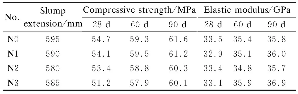
Tab.2 Workability and mechanical properties of concrete
1.2 Test program
Expansive deformation tests were conducted, including the free deformation test and the constrained deformation test, to measure the free deformation of concrete and the circumferential deformation of the steel tube in CFST, respectively. The free deformation test consisted of four groups of specimens(N0-N3). Each group had three specimens. All specimens had an identical dimension of 100 mm×100 mm×515 mm. A horizontal contractometer equipped with a dial gauge of ±0.01 mm accuracy was used to measure the horizontal deformation of the specimens. The test setup was according to “Standard for test methods of long-term performance and durability of ordinary concrete” (GB/T 50082—2009)[17]. Two measuring heads were in two ends of the specimens. The specimens demolded 24 h after casting. Then, the specimens were coated with vaseline and wrapped in plastic to simulate the closed environment in steel tube. The tests were conducted in the environment with a temperature of (20±2)℃. The length of the specimens was measured every day in the first 30 d, and then measured every 5 d. The test setup is shown in Fig.1.
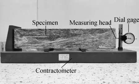
Fig.1 Test setup for free deformation test
In the constrained deformation test, the hoop strain of steel tube was measured to observe the expansion process of the self-stressing concrete. Six CFST columns were tested to study the influence of the steel ratio and dosage of EA on the expansion performance. The detailed specimen information is shown in Tab.3. All steel tubes (Q235) had an identical external diameter (159 mm) and height (477 mm), as shown in Fig.2. Both ends of the steel tube were welded on a steel plate to ensure a closed environment. Three strain gauges were attached in the middle of each steel tube, and the strain values were monitored continuously for 90 d. The temperature always remained at (20±5)℃ during the whole test.
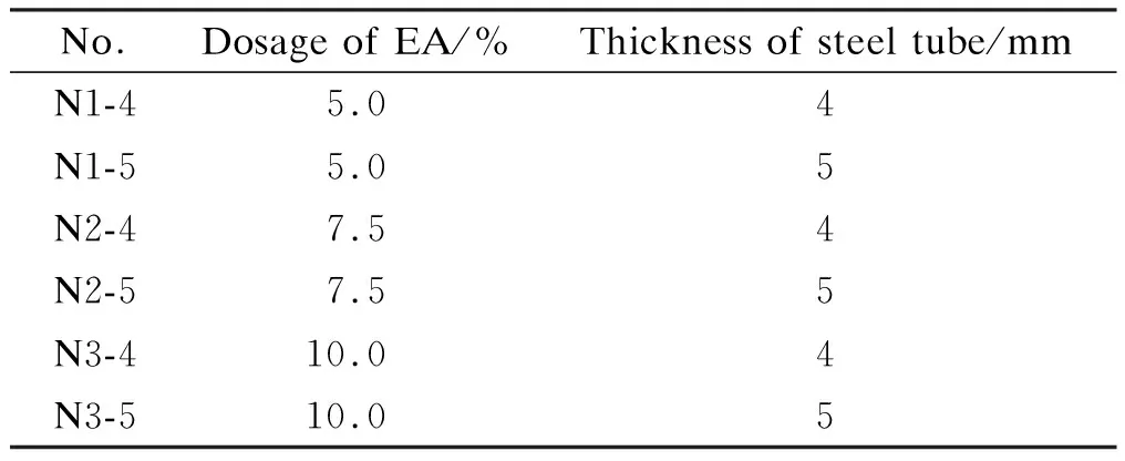
Tab.3 Detailed specimen information
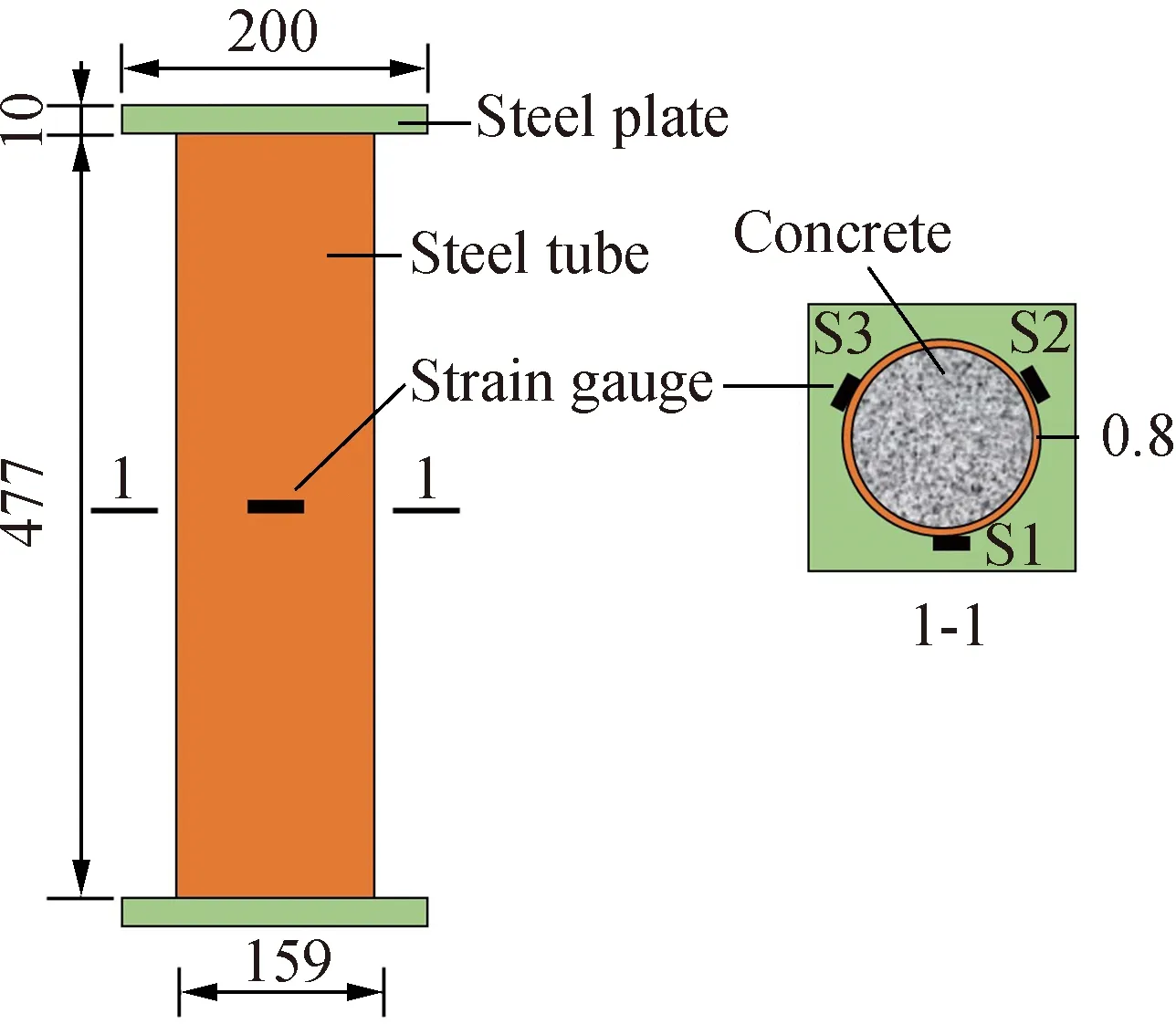
Fig.2 Dimensions of the CFST specimens(unit:mm)
1.3 Test result
The free deformation of concrete varied with the curing age, as shown in Fig.3(a). Specimen N0, without the addition of EA, exhibited a noticeable shrinkage with the increase in the curing age. In contrast, specimens N1-N3, which contained EA, expanded rapidly in the early stage. The free deformation of specimens N1-N3 reached the peak on the 6th or 7th day, then started to decline with the increase in the curing age. The free deformation of specimens N1-N3 was equal to the expansive deforma-tion minus the shrinkage deformation. The expansive deformation was caused by adding EA and was closely correlated with the dosage of EA.
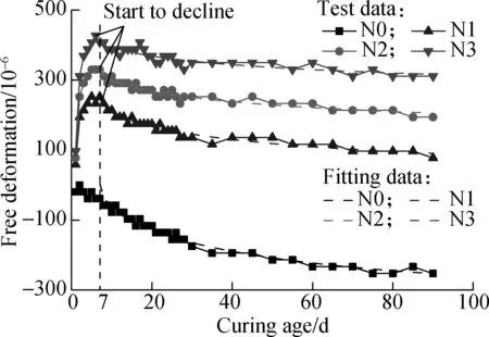
Fig.3 Free deformation-curing age curves
The free deformation of concrete started to decline on the 7th day, which indicates that the shrinkage is more dominant in subsequent deformation than the expansion. Thus, the following equation was used to predict the free deformation of concrete after 7 d of casting, which referred to the shrinkage model in CEB-FIP (1990)[18].
(1)
whereε0is the free deformation;tis the curing age; parametersA,BandCwere determined by the regression analysis of the test data, which were relevant to the dosage of EA. The free deformation of concrete was only related to the dosage of EA and the curing age. ParametersAandBdetermined the initial and final free deformation. ParametersBandCdetermined the variation rate of the free deformation. The values ofA,BandCfor the specimens are listed in Tab.4. ParametersA,BandChad an approximately linear relationship with the dosage of EA. Thus, the free deformation of concrete can be calculated by fitting above results.
(2)
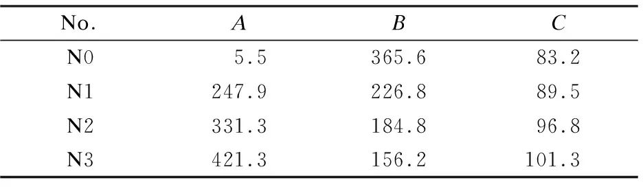
Tab.4 Fitting parameters for specimens N0-N3
The fitting curves of free deformation for specimens N0-N3 during 90 d are shown in Fig.3(a) by dash lines. Fig.4 depicts the free deformation of specimens N0-N3 during 360 d. The free deformation of specimens N1-N3 was still positive on the 360th day, indicating that the specimens were still expanding after 360 d.
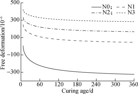
Fig.4 Free deformation-curing age fitting curves
In the CFST specimens, the expansion of internal concrete produced tension stress in the steel tube. The hoop strain of the steel tube exhibited the same variation trend with the curing age, namely the free deformation of concrete increased significantly in the initial 7 d and decreased later. An increase in the thickness of steel tube decreased the hoop strain, as shown in Fig.5.

Fig.5 Hoop strain-curing age curves
2 Analysis of Expansive Deformation and Self-Stressing Behaviour
2.1 Proposed calculation method
The CFST can be divided into two parts: steel tube and internal concrete. In the process of the stress analysis, the steel tube is thought to be subjected to a biaxial state of stress for simplicity. The stress state of a micro-unit in the steel tube is depicted in Fig.6.
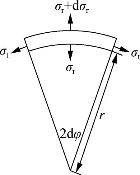
Fig.6 Stress state of a micro-unit in steel tube
According to the equilibrium condition, we have
(3)
whereris the radius of the micro-unit;σtandσrare the hoop and radial stress, respectively. Corresponding strainεtandεrcan be expressed as
(4)
(5)
whereuis the radial displacement of a cylindrical surface with a radius ofr.
The stress-strain relationship can be established according to the generalized Hook law as follows:
(6)
(7)
whereEsandμare the elastic modulus and Poisson’s ratio of steel, respectively.
The radial stress of the internal and external face of the steel tube are equal to the self-stress (q) and 0, respectively. Thus, the hoop and radial stress can be calculated by
(8)
(9)
whereaandbare the internal and external diameter of the steel tube, respectively.
It can be concluded that the hoop stress is significantly greater than the radial stress. The hoop stress of the internal and external face of the steel tube (σt,a,σt,b) are expressed as
(10)
(11)
wherekis a constant related to the dimension of the steel tube and is equal to (b2+a2)/(b2-a2).
The self-stress of the internal concrete ignoring the concrete creep can be expressed as
q=Ec(ε0-εR)
(12)
whereε0andεRare the concrete strain in the free and constrained state, respectively;Ecis the elastic modulus of concrete.εRis equal toεt,a, namely the hoop strain of the internal face of steel tube. Thus,εRandqcan be calculated by
(13)
(14)
Concrete creep occurs under the self-stress. The creep increases gradually with time and causes the self-stress to chang. Moreover, the growth rate of the creep is dependent on the self-stress. Thus, an iterative analysis should be adopted to study the self-stress development. The computing process is as follows:
1) Calculate the initial free expansive strainε0, constrained strainεR0and self-stressq0at timet0;
2) Determine the time step Δti(Δti=ti-ti-1);
3) Calculate the creep strainεciat timeti;

5) Iterate steps 2)-4) untiltireaches the target timeTor negativeεRiorqiappear. In the iterative analysis, the creep strain is calculated by the creep coefficient in CEB-FIP (1990)[18], which is only related to the material and curing environment. The concrete creep and self-stress are assumed to occur after 7 d of casting, which is because concrete hardening may not complete in the early stage. A detailed program flowchart is shown in Fig.7.
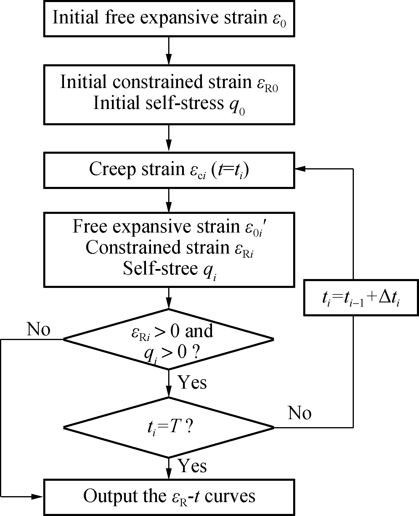
Fig.7 Program flowchart
2.2 Calculation result
2.2.1 Hoop strain of steel tube
The iterative analysis was conducted by software MATLAB. The hoop strain of the external face of steel tube calculated by MATLAB (solid lines) was compared with the experimental results, as shown in Fig.5. The estimated date agreed well with the test data, which indicates that the calculation method is capable of predicting the expansive deformation of CFST with reasonable precision. However, two apparent differences were observed between the test data and the estimated data. The peak values of the calculated curves were much smaller than those of the test curves. It is because the self-stress and concrete creep were already present during the initial 7 d, while they were not considered during the calculation process. The other difference was that the calculated curves decreased more rapidly and were lower than the test curves after 15 d. It is because the calculated curves were obtained based on the biaxial state of stress. However, the ends of the steel tube in the test were welded on steel plates to ensure a closed environment. The steel plates constrained the axial expansion of the internal concrete and produced axial tension strain in the steel tube. The measured hoop strain was greater than the calculated results due to the Poisson effect.
The estimated hoop strain of the steel tube during 360 d is shown in Fig.8. Both the hoop strain and its variation rate decreased with the increase in the curing age and tended to be stable finally. The hoop strain of specimens N1-4 and N1-5 were almost 0 on the 360th day. Thus, debonding may probably occur between the internal concrete and the steel tube due to the creep development when few EA were used. The hoop strain of specimens N2-4 and N3-4 were nearly 2 and 3 times that of specimen N1-4 on the 360th day, respectively. This indicates that increasing the dosage of EA can prevent the debonding effectively. The hoop strain of specimen N3-5 was smaller and declined more rapidly than that of specimen N3-4. The descending rate of the hoop strain was related to the self-stress. A corresponding explanation was stated in Section 2.2.2.
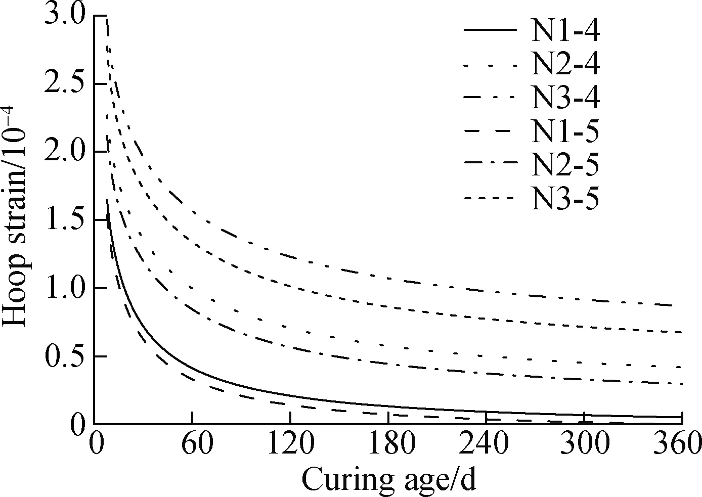
Fig.8 Calculated hoop strain-curing age curves
2.2.2 Self-stress of internal concrete
The estimated self-stress and creep deformation of the internal concrete during 360 d are shown in Fig.9 and Fig.10. The self-stress declined with the increase in the curing age due to the development of concrete creep and shrinkage. The loss of self-stress for all specimens were higher than 70% of the initial self-stress after 360 d. The self-stress and creep deformation were up to the expansive deformation, so they increased with the increase in the dosage of EA. For the specimens with the same dosage of EA, larger tube thickness offered a stronger constraint on internal concrete, and resulted in a larger initial self-stress and creep deformation. The self-stress of specimen N3-5 was higher than that of specimen N3-4 during the initial days. Meantime, the hoop strain of specimen N3-5 decreased more rapidly, as shown in Fig.6. However, the concrete creep and self-stress development were interactional. Large creep deformation accelerated the decline of self-stress. Fig.11 depicts the self-stress-creep deformation curves. Compared with the specimens with a tube thickness of 4 mm, the self-stress of the specimens with a tube thickness of 5 mm decreased more rapidly. The self-stress of specimen N1-5 was even smaller than that of N1-4 when the curing age reached 64 d. The creep deformation tended to be stable as the curing age increased. The creep deformation of the specimens ranged from 14.6×10⁻⁶to 35.6×10⁻⁶on the 90th day, accounting for 10%-22% of the free deformation, as shown in Fig.3(a). This indicates that the creep deformation cannot be ignored when studying the expansion performance of CFST columns.
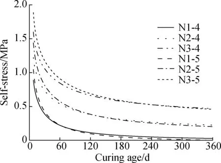
Fig.9 Calculated self-stress-curing age curves
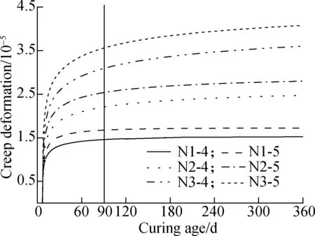
Fig.10 Calculated creep deformation-curing age curves
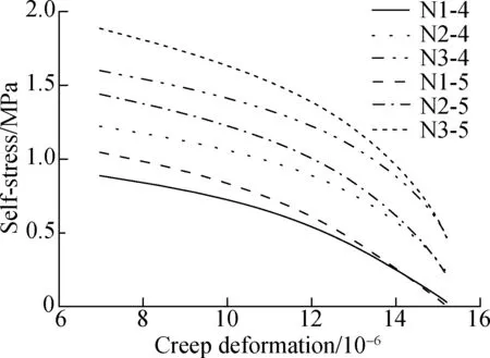
Fig.11 Calculated self-stress-creep deformation curves
3 Conclusions
1) The expansive concrete prepared in the study expands rapidly in the initial stage and shrinks gradually after 7 d. Free deformation of concrete increases with the increase in the dosage of EA. The expansive concrete with a 7.5%-10% dosage of EA can maintain expansion for a long time.
2) The hoop strain of the steel tube in CFST columns increases significantly in the initial 7 d and decreases later. Both increasing the dosage of EA and reducing the tube thickness increase the hoop strain. A proper addition of EA to internal concrete can prevent the debonding between steel tube and internal concrete.
3) The expansive deformation of CFST columns can be well predicted by the calculation method proposed in this study. The self-stress decreases with the increase in the curing age. The loss of self-stress for all specimens were greater than 70% of the initial self-stress after 360 d. Increasing the tube thickness of CFST columns increases the initial self-stress, while hastening the descending process of self-stress with the curing age.
4) Increasing the curing age, dosage of EA and tube thickness increases the creep deformation of concrete. Creep deformation affects the development of self-stress. Creep deformation accounts for 10%-22% of the free deformation, and cannot be ignored when studying the concrete deformation in CFST columns.
杂志排行

Journal of Southeast University(English Edition)的其它文章
- Coupling dimensions of human resource archetypes and organizational learning modes
- Min-max fuzzy model predictive tracking control of boiler-turbine system for ultra-supercritical units
- Firm review revelation policy considering social ties among consumers
- Fundamentals of quasigroup Hopf group-coalgebras
- A fault feature extraction method of gearbox based on compounddictionary noise reduction and optimized Fourier decomposition
- Effect of carbonation-drying-wetting on durability of coral aggregate seawater concrete