Unified Smith Predictor Based H∞ Wide-Area Damping Controller to Improve the Control Resiliency to Communication Failure
2020-05-22MithuSarkarBidyadharSubudhiandSandipGhosh
Mithu Sarkar, Bidyadhar Subudhi,, and Sandip Ghosh,
Abstract—Inter-area low frequency oscillation in power system is one of the major problems for bulk power transmission through weak tie lines. Use of wide-area signal is more effective than the local area signal in damping out the inter-area oscillations. Wide area measurement system (WAMS) is convenient to transmit the wide area signal through the communication channel to the remote location. Communication failure is one of the disastrous phenomena in a communication channel. In this paper,a dual input single output (DISO) H∞ controller is designed to build the control resiliency by employing two highest observability ranking wide area signals with respect to the critical damping inter-area mode. The proposed controller can provide sufficient damping to the system and also the system remains stabilized if one of the wide-area signals is lost. The time delay is an unwanted phenomenon that degrades the performance of the controllers. The unified Smith predictor approach is used to design a H∞ controller to handle the time delay. Kundur’s two-area and IEEE-39 bus test systems are considered to verify the effectiveness of the proposed controller. From the simulation results, it is verified that, the proposed controller provides excellent damping performance at normal communication and improves the controller resiliency to counteract the communication failure.
I. Introduction
LOW frequency oscillations (LFO) are one of the major problems for an interconnected power system. There are two forms of LFO, e.g., local area oscillation and inter-area oscillation. In case of local area oscillation, the generators of the same area are involved. A single generator or a group of generators oscillate against the rest of the generators in the same area, it can be defined as the local area mode of oscillation. The frequency range of this type of oscillations is about 1–2 Hz. Inter-area oscillation can be defined as when generators of one area swing against the generators of other areas in a wide area power system [1], [2]. The range of frequency of the inter-area mode is less than 1 Hz. The damping of this type of oscillation is very low. Hence, the power companies are concerned about the secure operation of the systems.Power system stabilizer (PSS) is widely used as a local controller to provide additional damping to the aforementioned oscillation. However, these local measurement based controllers are not appropriate to damp out the inter-area oscillations due to the low modal observability. The inter-area modes are spread to the multiple areas in the power system. Hence, a wide area signal based controller is more effective to provide the damping to inter-area oscillations [3].
The recent technologies such as wide area measurement system (WAMS) and phasor measurement unit (PMU) provide dynamic information about wide area signal and make it easier to transmit the wide area signal to the control site [4], [5]. Fast and reliable communication systems are necessary for wide area signal transmission. Even though the wide area signal gives accurate dynamic behavior of the system, but some communication problems, e.g., communication failure and time delay are associated with the transmission of the same. The communication delay may vary from 0.5 s to 1.0 s for wide area signal transmission [6], [7]. The variation of the time delay depends on the distance of communication line, the bandwidth of the communication channel and other communication factors. Due to the negative effect of the time delay, the controller performances may be degraded, as a result, the damping of the oscillation may be reduced even the system may be unstable. So, it is necessary to compensate the time delay at the design stage of the controller. A number of research works have been proposed to compensate the effect of the time delay[8], [9]. Pade approximation is one of the most conventional and widely used methods for modeling time delay [10], [11]. The effect of the order of Pade approximation on the damping of the inter-area modes is discussed in [8]. Choice of optimal order is required for Pade approximation to compensate the effect of delay properly. Unified Smith predictor (USP) based robustcontroller is designed for a plant with dead time [6] the controller provided satisfactory damping up to 1 s delay in the wide area signal. Several design approaches have been proposed in [6], [12], [13] for compensation the delay effect.
Due to communication failure, The wide area signal transmission is affected which leads to deterioration of damping performance of the controller. To resolve the above issue, suitable controller needs to be designed. A controller has been proposed in [14] in the cyber-physical system framework to secure the system from cyber attack and to improve the resiliency of the power system. Recently a goal representation heuristic dynamic programming (GrHDP)based WADC is proposed to address the issue of the communication failure in [15], [16]. Further, to handle the situation in which an actuator fails, a multi-objectivebased fault tolerant controller is proposed in [17] which provides a virtual actuator between the plant and controller.Sensor fault tolerant controller design approach has been proposed in [18], [19] to handle the communication failure.Recently a genetic algorithm based fixed order wide-area damping controller is proposed in [20] to handle the uncertainty and communication failure.
Also a number of solutions are proposed to address the issue of communication failure of the remote signal by using a local area signal as a backup feedback. A two level (centralized and decentralized) controller schemes is proposed in [4] by employing local and wide area signal respectively, where time delay in the wide area signal is compensated. It is shown in the above work that if the wide area signal is lost then local area based decentralized controller stabilizes the system. One local and one wide-area signals are employed to design a resilient controller in [11]. But the damping performance may be degraded as only the local signal is available when widearea signal is lost [15], [21]. Hence, it is a challenging task to provide the required level of damping performance by the local signals following loss of wide-area signal. Hence, it is the beneficial to employ multiple wide-area signals to improve the controller resiliency during communication failure.Several established methods use multiple wide-area signals as feedback to design the controllers [3], [22], [23]. But very few of them use multiple wide-area signals to handle the communication failure in power systems.
In view of the above, this paper presents a new approach to improve the controller resiliency (recovering the controller performances after the communication failure) by designing a DISOcontroller. It employs two wide area signals with the highest observability rank. The DISOcontroller comprises of two different single input single output (SISO) controllers. In a typical communication, both of the SISO controllers work simultaneously and provide adequate damping to the system.Unfortunately, if one of the wide area signals is lost, the DISO controller becomes a SISO controller, which utilizes the next highest observability ranking wide area signal and provides the damping to the system for stabilization. In this work, the time delay is considered in the wide area signals and the system is treated as a dead-time system. We propose a USP approach basedcontroller to handle the time delay.
The contributions of this paper are as follows:
2) USP approach is successfully applied to design acontroller with additional pole placement constraints to handle a range of time delay variation in the power system.
3) A comparison study is carried out with a conventional delay compensation technique given in [11]. The performance of the proposed controller is found to better than the later with higher delay range.
4) The performance of the proposed controller is also verified on a larger complex power system.
The rest of the paper is organized as follows. Section II describes the design of controller resiliency for a communication failure. Formulation of unified Smith predictor for a time delay system is presented in Section III.Mixed sensitivity basedcontroller procedure is briefly discussed in Section IV. Sections V and VI present simulation results obtained by using the resilient controller to the Kundur’s two area system and IEEE-39 bus test systems.Finally, conclusions are drawn in Section VII.
II. Controller Resiliency for Communication Failure
In this section, controller resiliency is built up by using two most efficient signals with the highest observability factors with respect to the most critical mode. When the most effective signal become unavailable due to any communication failure, the designed DISO controller acts as a SISO controller and provides damping to the system by using an alternative control input (next to the highest effective signal). Here the most effective signal that has the highest observability factor for most critical mode is referred to asand next highest effective signal is referred asAt first,is used to develop a supplementary controllerwhich is effective in the situation of communication failure.has the highest observability so, if we design a controller by usingit gives better damping performance. So, the controlleris designed by usingsignal considering a delay. At normal condition, both the controllers work simultaneously to improve the damping of the critical modes. To realize the problem, a DISOcontroller is presented here for a single input dual output (SIDO) plant as shown in Fig. 1.
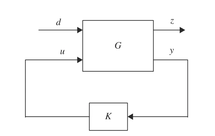
Fig. 1. General control structure.
A. Dual Input Single Output (DISO) Controller Concept for Single-Input Dual-Output (SIDO) Plant
The resilient controller can be formulated by adding an additional signalas feedback for the controller as shown in Fig. 2, whereis the plant,Kdenotes controller,defines as input,defines as performance output,denotes as measured output andis the disturbance. The measured outputis used as a feedback to the controller.

Fig. 2. DISO controller set up for SIDO plant.
Referring to Fig. 2, if the performance outputis used as the feedback signal, then another controller can be designed for the plant by using the signalSo, it is a SIDO system.Now the plantcan be described asandwhich represents as SIDO system.andare the transfer function for different outputs of the same plants. To achieve a good disturbance attenuation performance, thenorm of the transfer function fromtoshould be minimized.
By using co-prime factorization, the following expression can be obtained to design the DISO controller. The DISO controller can be described in terms of SIDO systems [11],[24]


B. Communication Failure Situation on Controller Performances
It is always not possible to obtain a wide area signal as a feedback of the controller due to communication network issues such as congestion of the communication medium and limited bandwidth availability. In this paper, the most effective wide area signalis considered as performance outputis taken as the measured outputWhen signalis not available,the SIDO system act as a SISO system and DISO controller becomes a SISO controller,hereis still present. The closed loop transfer function of the SISO controller (onlysignal is available)can be obtained as

It is observed that in the case of communication failure of the wide area signalboth of the transfer functions given in (5) and (6) do not contain the free parameterThe additional free parameterhelps to manipulate the transfer functionand also helps to minimizeBut in this case, ifdecreases thenincreases.So, there is a trade-off between the performance and the robustness. If we design another controllerthen another free parameteris introduced and the trade-off becomes less pronounced. The SISO feedback system has one degree of freedom in the controller design that is difficult to achieve all the desired goal. The parameterin the SIDO system adds an additional dimension for loop shaping. In DISO controller both of the signals are used as the feedback to get the desired frequency shaped which is easier than the SISO controller. In the communication failure, one signal is used as the feedback of the controller, so the controller gets one degree of freedom.Such condition is utilized to establish resilient control for the system. signalis always accessible even when the feedback signalis lost. So, at first, we design controllerby using signalto stabilize the system. But signalis more effective to provide the better damping performance. So,controlleris designed using the signalfor the updated plant as shown in Fig. 3. The updated plant is the open-loop plant integrated with controllerSo, by adding controllerthe free parametercan be added and the resulting DISO controller can fulfill the stability and robustness issues. But unfortunately, if signalis lost (communication fail) then the controllercan stabilize the system.
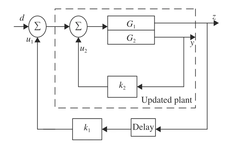
Fig. 3. Sequential controller design set up.
III. Unified Smith Predictor Approach for Time Delay System
The updated plant as shown in Fig. 3 can be expressed as a general state space form. The updated plant with the time delay can be expressed asas shown in Fig. 4,whereis the delay free augmented plant,is the time delay in the measurement output with a dead timeKis the controller to be designed for the dead time system.

Fig. 4. Plant layout with controller and time delay.
The state space representation of the generalized reduced order plant with the considered weights is given by

In this case, the above mentioned reduced order plant is the updated closed loop plant with the weights as shown in Fig. 3.Now, with the consideration of delayin the wide area signal, the expression of the plant model can be obtained by MSP as

The presence of any fast eigen value inyields a complicated computation leading to a complex numerical problem. But, in the meantime, the above computational problem can be addressed by using USP [28]. This numerical problem can be solved by splitting the delay free plant (P) into a stable partand an unstable partwith the help of any suitable transformation matrix. After the transformation,the delay free plant is given by
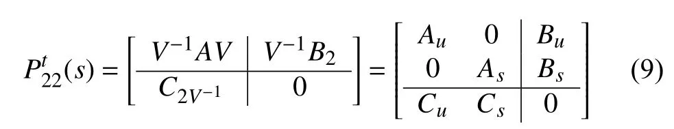
where the transformation matrixcan be obtained in such a way that the system matrixAcan be expressed as Jordan Canonical form.eigfunction available in MATLAB can be used to obtain the transformation matrix. By usingcdf2rdffunction, the transformed matrixis converted from complex diagonal form to real diagonal form.is the critical or unstable part ofAandis the stable or noncritical part ofA. The system matrixAis decomposed by splitting the complex plane along vertical linewithα is chosen as the maximum negative real part of poorly damped poles. Here,are all the eigenvaluesofwithandare the remaining eigen values ofThe delay free augmented plant (9) can be expressed as in terms of stable and unstable part, i.e.,where
and

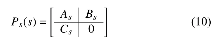
The predictor for the stable or noncritical part of the system is considered as CSP

and MSP is considered for unstable or critical part of the predictor as

where

Now the USP for dead time plantis defined as
The expression for the USP in terms of CSP and MSP is given by


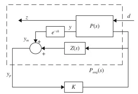
Fig. 5. Formulation of USP for time delay system.
The overall expression of the generalized plant can be formulated fromto design the controller for dead time plant is given in [28].

After formulation of the generalized plantby using the USP approach as shown in Fig. 5, the controlleris to be designed to achieve the desired damping performance. Now, if the controlleris enabled to provide the desired damping performance for the augmented plantthencan also compensate the time delay effect on the system.
IV. H∞ Controller Design
The objective is to minimize the disturbance and noise of the system. A sudden change of load, any fault in the system are the causes of the disturbance in the power system. Both of the controllers are designed with the help mixed sensitive approach. In order to formulate amix sensitivity control problem, the plant with the controller configuration is shown in Fig. 6. Usually, it is a disturbance rejection problem set up,whereis the plant, andis the controller anddefines as the disturbance of the plant.andare the weighting functions used to shape the open loop plant.is chosen as a low pass filter for disturbance rejection andis a high pass filter to reduce the control effort and increase the robustness. To achieve the objective, a robust controllerhas to be designed so that, the infinity norm of the closed loop transfer function including the weighted function should be minimized [22], [29].

Fig. 6. Standard control problem set up.
The objective of the mixed sensitivity basedcontroller can be expressed as


Fig. 7. LMI region for pole placement.
The following steps are carried out to design the proposed resilient controller:
Step 1:Linearize the nonlinear plant and determine the system modes.
Step2:Reduce the order ofto suitable order for flexibility and simplicity.
Step3:Design acontrollerusing LMI Toolbox by using the wide signal
Step4:Determine the closed loop system usingConsider this closed loop plant as the new plant that has to be stabilized.
Step5:Reduced the order of new plant with the wide area signal
Step6:Formulate the generalized plant as described in Section III using the reduced order plant and the mixedsensitivity weights. Treat this plant as an updated plant.
Step7:Design again acontrollerfor the updated plant.
Step8:Reduce both controllers to suitable orders.
Step9:Test both controllers on the real plant (full order).
V. Case Study I

Fig. 8. Single line diagram of 11 bus test system.
In order to implement the proposed resilient controller, the well-known Kundur’s two-area power system is considered as shown in Fig. 8 . The system consists of 11 buses and 4 generators. Two areas are connected by a weak tie-line. Each area consists of two generators and generator 1 is equipped with local PSS. The system parameters are given in [1].The nonlinear system is linearized around an operating point of 400 MW power transfer from Area-1 to Area-2. Modal analysis of the linearized open-loop system is performed.From the modal analysis, three electromechanical modesandare found. The frequency/damping ratio of the oscillations areandrespectively. From the mode shape, it is obtained that all the generators are involved inmode. So,modeis an inter-area mode. generator 1 and generator 2 participate inmode and generator 3 and generator 4 participate inmode. So,andare the local modes.As local PSS is connected with generator 1 so, the damping of the local modesis relatively high thanThe transmission line active power deviation is chosen as the feedback signal for controller design. The feedback signalsandare selected by a large value of observability factor with respect tomode.andare found to be the largest observability factor. So,andare chosen asandrespectively.andare the active power flowing through the line connecting busesandrespectively. From the controllability factor analysis,generator 4 is selected as the controller location [32]. After selectingandandcan be determined. The higher orderis reduced toorder for simplicity by balance truncation method [29]. The frequency response of the full order plant and reduced order plant are shown in Fig. 9. It is observed from Fig. 9 that, the response of the reduced order plant is almost identical to the full order plant.

Fig. 9. Singular value plot of original system and reduced order system.
Now, the supplementary controlleris to be designed by using the signalas the feedback signal.andare weighting functions for reducing the control effort and disturbance rejection. The weighting functions to design the controlleris considered asand
A. Performance Evaluation and Simulation Result
To evaluate the performances of the two controllersandthree different situations are considered such as without controller, communication failure of wide-area signal and normal communication. At normal condition, when both of the signalsandare present and time delays are considered in the remote area signalIn the communication failure, remote area signalis lost and onlysignal based controlleris present. Another condition is considered when only PSSs are present in the system (without controller). At normal condition (with both controllers), the damping of the inter-area modeis improved from0.032 toUnder communication failure condition (with onlythe damping of the inter-area mode becomes 0 .1537. To verify the performance of the designed controllers, nonlinear simulation is carried out for 15 s. For the nonlinear simulation,a pulse disturbance of magnitude of 0.05 pu is given after 1.0 s simulation at generator 2 terminal as the change in voltage reference. Different values of time delays, i.e., 500 ms, 750 ms, and 1.0 s are considered in the simulation stage to validate the effectiveness of the designed controllers.
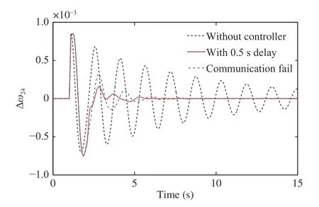
Fig. 10. response for 500 ms transmission delay.
The speed deviation of the generator 2 and generator 4 as shown in Fig. 10 represents the inter-area mode. 500 ms time delay is considered insignal at the simulation. It is observed from Fig. 10 that, when there is no communication failure, the controllers provide sufficient damping and the inter-area mode is settled down with in 5–6 s. In case of communication failure, thesignal based controller performs alone and brings the system stabilized with in 8 s.
The speed deviations of the generator 3 and generator 4 represent the local area modesThe performance of the controllers can be observed on the local mode from Fig. 11.The damping is improved at the normal condition as well as communication failure condition. There is no significant change in the oscillation between normal and communication failure condition. Active power deviation through tie lineis also taken as a monitoring variable. The effect of the controllers on the active power deviation is presented in Fig. 12. The oscillations are damped out with in almost 5–7 s.
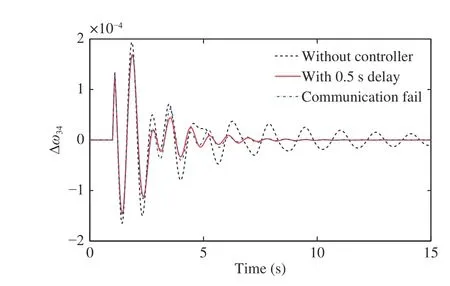
Fig. 11. response for 500 ms transmission delay.
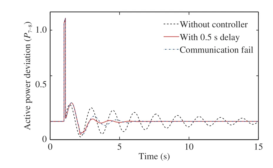
Fig. 12. response for 500 ms transmission delay.
Next, a 750 ms delay is considered in the simulation and the performances of the controllers are investigated. From Figs.13–15, it is seen that, at normal communication, the controllers act simultaneously and provide adequate damping to the system.
Figs. 16–18 show the performance of the controllers, when a 1.0 s transmission delay is considered. It is observed from Figs. 16–18 that, the performance of the controllers is very slightly degraded at normal operation. The oscillation of the inter-area mode is disappeared within 2–3 cycles of operation.Thus, it is observed that the proposed controller exhibits superior damping performance. The performance of the controllers on the local modes is almost identical to normal condition and communication failure condition.

Fig. 13. response for 750 ms transmission delay.
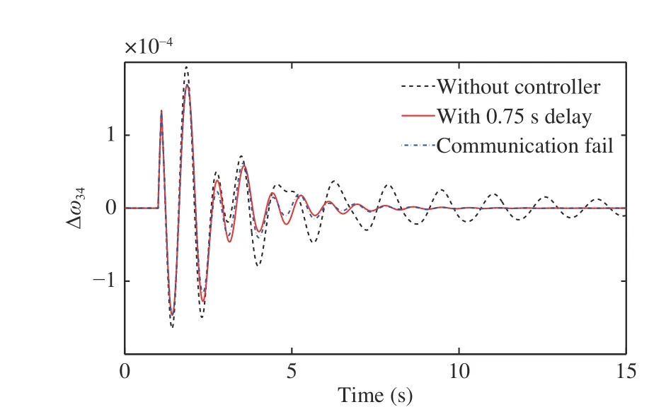
Fig. 14. response for 750 ms transmission delay.

Fig. 15. response for 750 ms transmission delay.

Fig. 16. response for 1.0 s transmission delay.
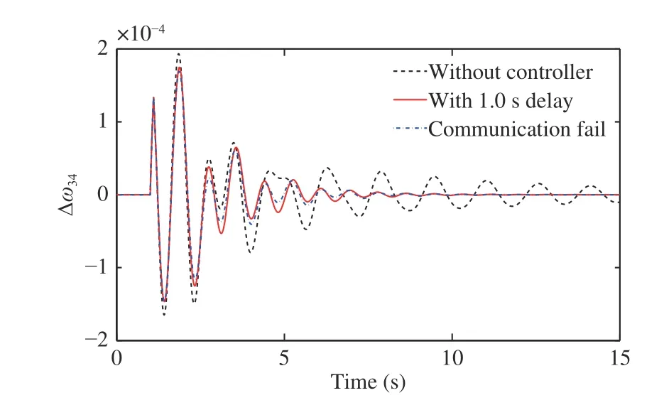
Fig. 17. response for 1.0 s transmission delay.

Fig. 18. response for 1.0 s transmission delay.
Fig. 19 shows that the response ofunder normal condition when delay is considered in both wide area signals(nadIt is shown from Fig. 19 that the damping reduces slightly when 500 ms delay is considered in both wide area signals but still the oscillations are died out within 10 s.

Fig. 19. at nominal communication with 500 ms delay.
Next, a comparison study is carried out with the existing method given in [11], where time delay is modeled with second order Pade approximation and based on integrated model (open loop plant and approximate model), acontroller is designed. Here, the controlleris the same as previously used. The time delay is modeled withorder Pade approximation [11]. An augmented plant is formulated with the new plant described in Step 5 and theorder delay. A conic sectoris taken to ensure a minimum damping ratio of 0.15. Thencontroller is designed for augmented plant considering 500 ms delay.Fig. 20 shows that both the controllers (proposed and existing)provide sufficient damping to the system when 500 ms delay is considered insignal. But it is observed from Fig. 21, that with 750 ms delay, the proposed controller gives a better response than the existing one. The settling time of the interarea oscillation is lesser for the proposed controller than the existing one.

Fig. 20. response with USP based controller and existing method based controller under 500 ms delay in signal.

Fig. 21. response with USP based controller and existing method based controller under 750 ms delay in signal.
It is also observed from Fig. 22 that when 500 ms delay is considered in both signals, the system remains stable and inter-area oscillation is damped out within 10 s with the USP based controller, the system becomes unstable for the controller designed using the method [11].

Fig. 22. response with USP based controller and existing method based controller under 500 ms delay in both signals.
VI. Case Study II
To verify the performance of the proposed controller, we next consider a more complex system, i.e., 10-machine 39-bus test system as shown in Fig. 23. All the system parameters and local PSSs data as in [33], [34]. Generator 1 to generator 9 are equipped with local PSSs. From the model analysis of the open loop system, three inter area-modes are found. The frequency/damping ratio of the three inter-area modes are found asandrespectively. The second and third modes have low damping but high frequency compared to the first mode. The settling time of the second and third mode is almost 10 s to 12 s.Hence, no damping controller is required for those two modes.So, our prime concern is to improve the damping of the first inter-area mode.
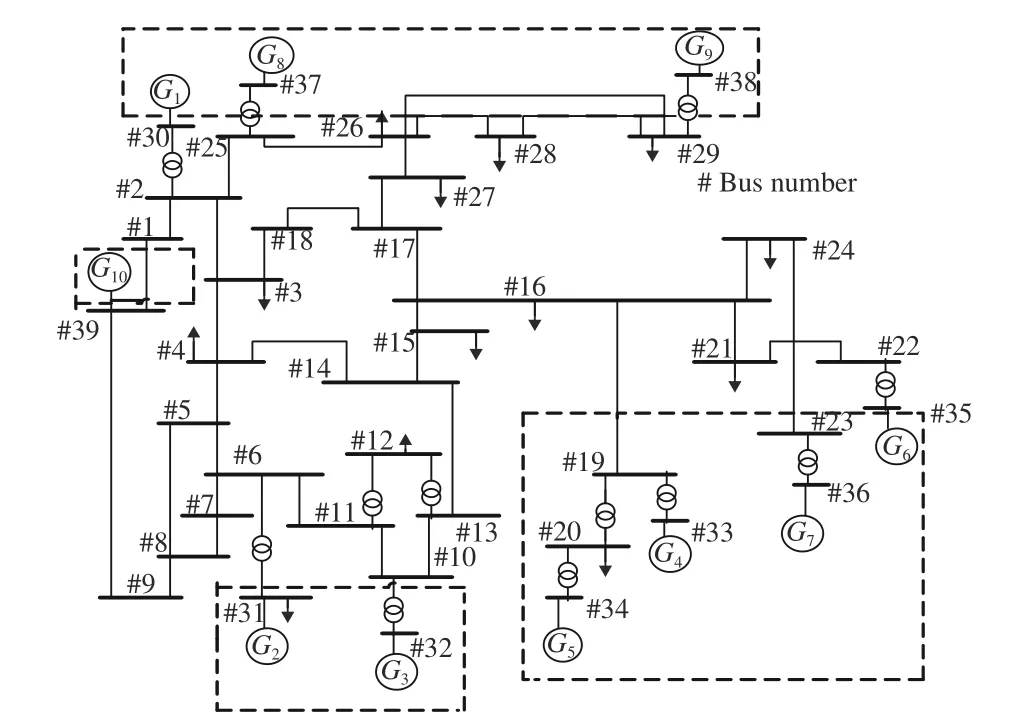
Fig. 23. Single line diagram of 10–machine 39-bus system.
The deviation of the active power flow through the tie line is considered as the feedback signal for the controllers.Geometrical controllability and observability are measured for selecting the most appropriate signals and controller location.By controllability and observability factor analysis,andare chosen asandrespectively and generator 4 is chosen as the controller location [32].andare the active power flowing through the line connecting buses 12 and 13, 3 and 18, respectively.

Fig. 24. Singular value plot of
A. Performance Evaluation and Simulation Result
It is observed from the modal analysis that, when both the controllers act simultaneously, the damping of the critical inter mode is significantly increased fromtoFor communication failure condition, the controllercan stabilize the system and improves the damping of critical inter area mode fromto
For the nonlinear time domain performance of the controllers, a 0.2 s pulse disturbance of magnitude of 0.05 pu is given at generator 4 terminal as the change in voltage reference. Different values of time delays (500 ms, 750 ms,and 1 s) are considered in simulation. The speed deviation between generator 4 and generator 10 represents response corresponding to the critical inter-area mode of the system. At normal condition, when 500 ms delay is considered insignal, Fig. 25 shows that both the controllers provide sufficient damping and the inter-area mode settles down within 6–7 s. In the event of communication failure, thesignal based controller performs alone and still helps the system to be stabilized. Figs. 26 and 27 show the performances of the controllers when 750 ms and 1.0 s transmission delay is considered respectively. The controllers still settle down the oscillations within 10 s. Thus it is clear that the controllers provide excellent performance for a wide range of delay variation.
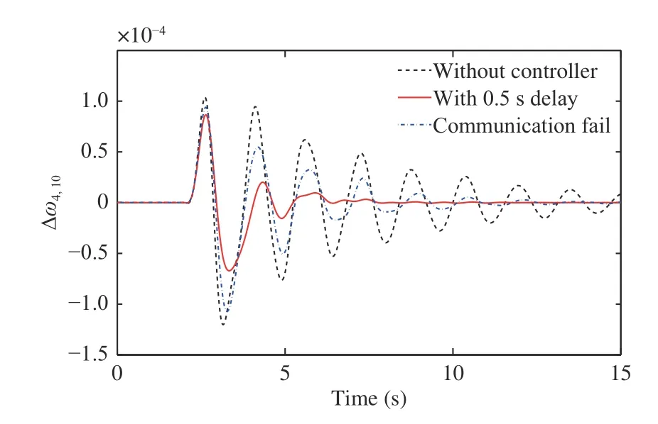
Fig. 25. response for 500 ms transmission delay at normal communication.
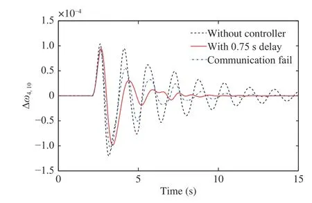
Fig. 26. response for 750 ms transmission delay at normal communication.

Fig. 27. response for 1.0 s transmission delay at normal communication.
Figs. 28 and 29 show the responses for the local-area modes, when 500 ms and 1.0 s delay are considered,respectively. In case of local mode, Figs. 28 and 29 show that the controllers are performed well for 500 ms delay but performances degrade significantly for 1.0 s delay.

Fig. 28. response for 500 ms transmission delay at normal communication.

Fig. 29. response for 1.0 s transmission delay at normal communication.
The effect of the time delay is also evaluated in the active power flow in the tie-line. Figs. 30 and 31 show the active power deviation response ofwhen 500 ms and 1.0 s delay is considered. It is observed from Figs. 30 and 31 that,the oscillations are settled within 1.0 s when both the controllers act simultaneously.

Fig. 30. response for 500 ms transmission delay at normal communication.

Fig. 31. response for 1.0 s transmission delay at normal communication.
Here, also a comparison study is a carried out with the existing method [11] the same as earlier. It is observed from Fig. 33 that both of the controllers are able to provide adequate damping to the system when 500 ms delay is considered insignal. But when 750 ms delay is considered,it can be seen from Fig. 34 that the performance is better for USP based controller.

Fig. 32. under normal communication with 500 ms delay.

Fig. 33. response with USP based controller and existing method based controller under 500 ms delay in signal.
It is also shown in Fig. 35 that when there is a 500 ms delay in both signalsthe USP based controller can stabilize the system within 10–12 s, whereas when the controller reported in [11] is applied the system becomes unstable.
VII. Conclusion
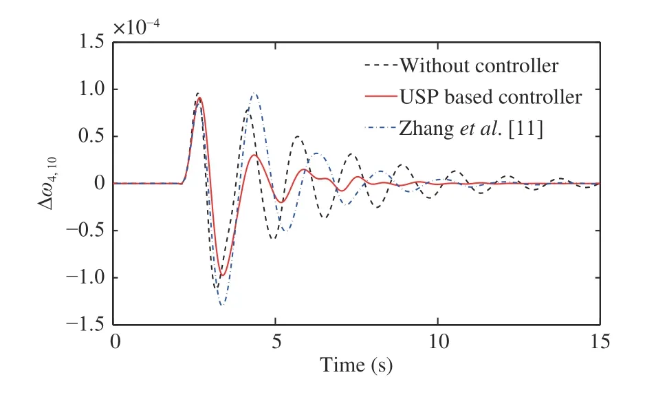
Fig. 34. response with USP based controller and existing method based controller under 750 ms delay in signal.
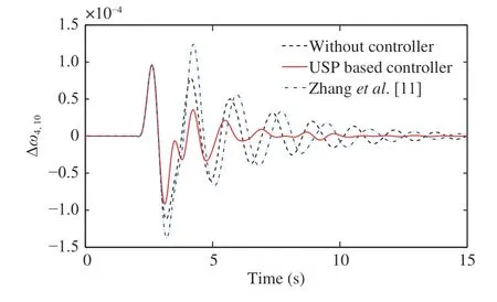
Fig. 35. response with USP based controller and existing method based controller under 500 ms delay in both signals.
Acknowledgment
The first author would like to thank Dr. Song Zhang and Mr. Chinna Obaiah Maddela for their suggestion during the research.
APPENDIX
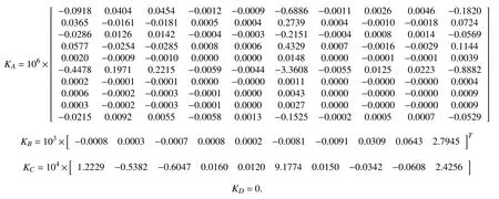
The state space representation of controller K1of 2-area system is


The state space representation of controllerK1of 39 bus power system is
杂志排行

IEEE/CAA Journal of Automatica Sinica的其它文章
- Artificial Intelligence Applications in the Development of Autonomous Vehicles: A Survey
- Data-Driven Based Fault Prognosis for Industrial Systems: A Concise Overview
- Review of Antiswing Control of Shipboard Cranes
- Research Progress of Parallel Control and Management
- Influence of Data Clouds Fusion From 3D Real-Time Vision System on Robotic Group Dead Reckoning in Unknown Terrain
- Effect of a Traffic Speed Based Cruise Control on an Electric Vehicle’s Performance and an Energy Consumption Model of an Electric Vehicle