A Delay-Dependent Anti-Windup Compensator for Wide-Area Power Systems With Time-Varying Delays and Actuator Saturation
2020-02-29MaddelaChinnaObaiahandBidyadharSubudhi
Maddela Chinna Obaiah, and Bidyadhar Subudhi,
Abstract—In this paper, a delay-dependent anti-windup compensator is designed for wide-area power systems to enhance the damping of inter-area low-frequency oscillations in the presence of time-varying delays and actuator saturation using an indirect approach. In this approach, first, a conventional wide-area damping controller is designed by using H ∞ output feedback with regional pole placement approach without considering time-varying delays and actuator saturation. Then to mitigate the effect of both time-varying delays and actuator saturation, an add-on delay-dependent anti-windup compensator is designed. Based on generalized sector conditions, less conservative delay-dependent sufficient conditions are derived in the form of a linear matrix inequality (LMI) to guarantee the asymptotic stability of the closedloop system in the presence of time-varying delays and actuator saturation by using Lyapunov-Krasovskii functional and Jensen integral inequality. Based on sufficient conditions, the LMI-based optimization problem is formulated and solved to obtain the compensator gain which maximizes the estimation of the region of at-traction and minimizes the upper bound of L2-gain. Nonlinear simulations are performed first using MATLAB/Simulink on a two-area four-machine power system to evaluate the performance of the proposed controller for two operating conditions, e.g.,3-phase to ground fault and generator 1 terminal voltage variation. Then the proposed controller is implemented in real-time on an OPAL-RT digital simulator. From the results obtained it is verified that the proposed controller provides sufficient damping to the inter-area oscillations in the presence of time-varying delays and actuator saturation and maximizes the estimation of the region of attraction.
I. INTRODUCTION
CURRENTLY, wide-area power systems (WAPSs) are formed by the interconnection of regional power systems to meet the growing demand for electric power [1]. WAPSs offer numerous advantages, such as increased capability and efficiency of generation allocation, and enhancement of redundancy [2]. The western electricity coordinated council(WECC) system in US is one of the typical examples of WAPSs. Inter-area oscillations (0.2-1.0 Hz) have a large influence on the operation of WAPSs due to the involvement of many generators and different areas, which reduces the power transfer capability between areas and can even cause the system instability. These oscillations are time-critical and grow in magnitude within a few seconds if they have insufficient damping, which can then lead to system separations and blackouts. The WECC system blackout on August 10, 1996, is an examples of this [2]. Traditionally, these oscillations are damped-out by using conventional power system stabilizers(CPSSs) by providing additional damping control to automatic voltage regulators (AVRs) on the generators or flexible AC transmission systems (FACTS) devices with their supplementary damping control. CPSSs provide sufficient damping to local area oscillations by using local measured signals as their feedback signals. However, these damping controllers with local signals provide less damping to inter-area oscillations due to the lack of global observability of locally measured signals [3].
With the development of wide-area measurement systems(WAMS), the aforementioned problem can be overcome by using wide-area feedback signals to PSSs and FACTS devices[4]. The damping controllers designed by using wide-area signals to improve the stability of the WAPS by integrating the inter-area oscillations are called wide-area damping controllers (WADCs). The performance of WADCs is adversely affected by time delays, which occur due to the usage of a communication network for transferring wide-area signals from remote areas to a control center and vice versa.These time delays are unavoidable in wide-area power systems, which also degrade damping performance or may even cause closed-loop system instability [5]. The duration of time delays depends on the transferred distance, type of the communication network and protocol used for transmission.Therefore, it is essential to consider the time delays for design of suitable damping controllers and find the time delay margin in which the wide-area power system remains stable. Various WADC design techniques are reported in the literature to guarantee the stability of the system by compensating the effect of time-delays [6]-[10].
On the other hand, actuator saturation is an inevitable nonlinear phenomenon in a control system due to the physical limitations of the actuator output signal which is limited by its minimum and maximum values. The presence of actuator saturation causes degradation in the performance of the closedloop system or even makes it unstable [11]. Several methods have been presented in the literature [11]-[13] to address the stability of a system under actuator saturation. Two approaches are provided for the studying the effect of actuator saturation,e.g., direct approach and indirect approach. In the direct approach, the actuator saturation is considered at the beginning of control design [14], [15]. In the indirect approach, a conventional controller is first designed without considering saturation and then designed with an add-on anti-windup compensator to minimize the adverse effect caused by actuator saturation nonlinearity [12], [16]. Among these two approaches,an indirect approach, which is also known as an anti-windup method is the most popular in practice.
Power system damping controllers usually have saturation limits, which are different from the traditional magnetic saturation of generators. These saturation limits are either intentionally designed or resulted from the practical limitations of the equipment ratings [17]. Due to the unavoidable physical limitations of the actuator, actuator saturation occurs in the operation of the power system when it is driven by the signals generated from the designed damping controller. The saturation affects the capability of damping oscillations of the designed damping controller by enforcing the actual damping controller outputs within a range of permissible output values. The restrictions in the damping controller output reduce the control signal necessary for the damping of oscillations and consequently affects the overall system dynamic performance [18]. Hence, it is imperative to design an appropriate damping controller such that it enhances the stability of the system in the presence of actuator saturation. In the literature, substantial research has been undertaken to model and study the effect of time-varying delays on power system stability ([6]-[10], and references therein), but very few works have been reported on the effect of actuator saturation on power system stability [17]-[21].However, to the author’s best knowledge, most of the damping controllers proposed in the power system literature have not considered the effect of time-varying delays and actuator saturation simultaneously.

1) This paper addresses the issue of problems arising in the feedback loop of a power system due to the usage of a communication network and the physical limitations of the controller device such as time-varying delays and actuator saturation.
2) To compensate for the effect of both time-varying delays and actuator saturation on the damping of inter-area oscillations of wide-area power system, a delay-dependent anti-windup compensator is proposed for supplementary damping control of flexible AC transmission systems (FACTS) devices.
3) An appropriate Lyapunov-Krasovskii functional and an integral inequality along with a reciprocally convex approach have been employed to obtain less conservative sufficient conditions which guarantee the asymptotic stability of the closed-loop power system.
4) Based on these conditions, the LMI-based optimization problem is formulated and solved to obtain the anti-windup compensator gain, which maximizes the estimation of the region of attraction and minimizes the upper bound ofL2-gain.
5) The effectiveness of the proposed controller is verified on a two-area four-machine power system with a Thyristor controller series capacitor (TCSC) in both a MATLAB/Simulink and OPAL-RT real-time digital simulator.

Fig. 1. Block diagram of power system with an anti-windup control.
The rest of the paper is organized as follows. The problem formulation and preliminaries are presented in Section II. In Section III, an anti-windup synthesis with time-varying delay is presented by using the Lyapunov-Krasovskii functional and Jensen integral inequality. Two convex optimization problems are presented in Section IV. In Section V, nonlinear simulation results obtained using MATLAB/Simulink on a two-area four-machine power system are presented. In Section VI, real-time results obtained using Opal-RT, a real-time digital simulator to validate the effectiveness of the proposed controller in real-time are presented. Finally, conclusions are presented in Section VII.
Notations:Throughout this paper, Rndenotes thendimensional Euclidean space. Rn×mis the set of alln×mreal matrices. The superscriptsTand -1 defines the transpose and the inverse of a matrix, respectively.P=PT>0(≥0) denotes thatPis a real symmetric positive-definite (positive semidefinite) matrix. diag{···} denotes a block-diagonal matrix.Idenotes the identity matrix with appropriate dimensions. The symmetric term in a symmetric matrix is denoted by “*”.
II. PROBLEM FORMULATION AND PRELIMINARIES
An interconnected power system consists of various components such as synchronous generators with their excitation systems (IEEE-ST1A), PSSs, and FACTS controllers such as TCSC, SVC, etc. and several loads. The above components are interconnected through a transmission network. A set of nonlinear differential algebraic equations(DAEs) represents an interconnected power system with the aforementioned components [32].
The linearized state space model of the pre-fault open-loop power system by excluding a wide-area damping controller(WADC) at an equilibrium point is given by

In low-frequency inter-area oscillation studies, fast dynamics are not considered. Hence, the full-order model of the system is not necessary to consider in controller design.To simplify and speed up the controller design procedure, it is necessary to reduce the system order. By employing the Schur model reduction method [33], the full-order model is reduced where only the poorly damped electromechanical modes are obtained. The linearized reduced model (1) is written as

wherexp(t)∈Rnpis vector of reduced order state variables andAp,Bp,C1,C2, andD2are known constant reduced real matrices with appropriate dimensions.
To enhance the damping of inter-area oscillations of WAPS described by (3), we consider the following dynamic output feedback WASDC in the absence of time-varying delays and actuator saturation:

wherexc∈Rnc,y∈Rpandyc∈Rmare vectors of the controller states variable, controller input and controller output respectively.
In this paper,H∞mixed-sensitivity formulation with the robust pole placement approach presented in [34] is considered to design the WASDC (4) to enhance the damping of inter-area oscillation in the absence of time-varying delays and actuator saturation.
Remark 1 [34]:For system (3), if there existnp×npmatric esR>0,S>0 ,nc×ncmatrixmatrixandm×ncmatrixsuch that

where

Moreover, matricesMandNare formulated from the singular value decomposition (SVD) ofI-RS, namely

Then the parameter of the dynamic output feedback controller in the form of (4) that places the closed-loop poles in the regioncan be computed as

Consider the time-varying delay in the feedback loop in Fig. 1.To compensate the effect of time-varying delay, WASDC (4)can be rewritten as follows:

where τ(t) denotes the time-varying delay that occurs in the feedback loop.
Assumption 1:τ(t) is a continuous function satisfying 0 ≤τm≤τ(t)≤τMand τ˙(t)≤ρ, where τm, τMare given positive scalars representing the lower and upper bounds of interval time-varying delay τ(t), and ρ is the upper bound of
Consider that the controller output is saturated by following limits:

In the presence of actuator saturation, the open-loop system(3) can be expressed as
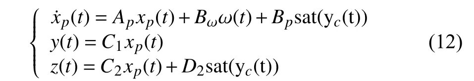
The designed WASDC (4) guarantees the stability of the closed-loop system in the absence of time-varying delays and actuator saturation. To mitigate the effect of time-varying delays ( τ(t)) and actuator saturation (s at(yc(t)))simultaneously, the controller form is modified by adding an anti-windup compensator (AWC) using a dead-zone sector nonlinearity as follows:

whereEcis a static anti-windup compensator gain, and the effect of AWC’s takes place only when the saturation occurs.
To mitigate the effects of time-varying delays and actuator saturation, from (12) and (13), the closed-loop power system becomes

Define an augmented vector

and the matrices

The augmented system can be written as

where ψ (Kη(t))=yc(t)-sat(yc(t))) is a dead-zone nonlinearity.
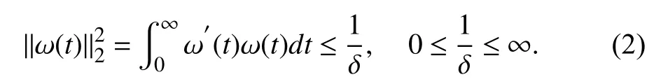
Definition 1:The estimate of the region of attraction (ROA)for the closed-loop system (17) with given initial condition φ(θ)is defined as

The objective of the paper is to design an anti-windup compensatorEcfor theH∞output feedback WASDC (4) to reduce the effect of time-varying delays and actuator saturation such that the closed-loop system (17) is asymptotically stable for all initial conditions φ(θ) belonging to the set χδ. Some of the useful Lemmas are presented for stabilization of the anti-windup compensator.
Lemma 1 (Jensen’s inequality) [26]:For any constant matrixtwo scalars τM≥τm≥0, and vector functionsuch that the following integration is well defined, it holds that:

Lemma 2 [31]:For any constant matrixmatrix


Lemma 3 [35]:Ifyc(t) and ν are elements of the set

then the nonlinearity ψ(Kη(t)) satisfies the following inequality:

whereT0∈Rm×mis any positive diagonal definite matrix.
III. ANTI-WINDUP SYNTHESIS WITH TIME-VARYING DELAY
TheH∞output feedback WASDC (4), guarantees the asymptomatic stability of the closed-loop system in the absence of actuator saturation and time-varying delays.However, the presence of time-varying delays and actuator saturation degrades the performance of the designed damping controller (4) and even may lead to instability of the closedloop system. In this section, we propose an anti-windup compensator design for the closed-loop system to compensate for the effect of both actuator saturation and time-varying delays using the Lyapunov-Krasovskii functional and Jensen integral inequality. Less conservative sufficient conditions formulated in the form of LMIs are given in Theorem 1.
Theorem 1:For a given scalarsand α >0, the closed-loop system (17) with anti-windup compensator gainEc=JF-1is asymptotically stable and possessesH∞performance index γ for actuator saturation and any timevarying delay τ(t) satisfying (6) and (7) respectively, if there exist symmetric positive definite matricespositive definite diagonal matrixF∈Rm×m, matrices∈Rnc×mand a positive scalar γ satisfying the following LMIs:

where

and

Proof:Consider the following Lyapunov-Krasovskii functional

whereX,Y1,Y2,Y3,Z1andZ2are positive definite symmetric matrices which are to be determined.
The time derivative ofV(t) along the trajectories of the closed-loop system (17) is given by

According to Lemma 1, we have the following inequality

when
According to Lemma 2, the following can be derived

From Lemma 3, for a matrixif the vectorη belongs to the following set

then the nonlinearity ψ(Kη(t)) satisfies the following inequality:

By considering the generalized sector condition (32), the time derivative ofV(t) is extended to

For any (np+nc)×(np+nc) matricesP1andP2, it is seen from (17) that

Substituting (28) and (30) into (27), and adding the left sides of (34) to (33), we have

Define an auxiliary function forH∞performance of the system (17),

and using the Schur complement, we have the following inequality

where

with

From (37), if Ψ <0, then the auxiliary functionM(t) is negative definite, which ensures that the closed-loop system is asymptotically stable.
In order to obtain an anti-windup compensator gainEc,introduce some change of variables as

ConsideringP2=αP1, where α is a scalar tuning parameter and pre- and post-multiply the inequality Ψ <0 by Π and Π′respectively, withthat is

From (38), we obtain the (24).
In order to include actuator saturation in the controller design, we consider a sector constraint as follows

By using Schur complement, we can rewrite as


We use the information of the lower bound (as upper limit of the second integral term) and derivative (in both integral terms) of the time-varying delay in the LKF formation to reduce the conservatism of the stability conditions.
Remark 3:In [8], [10], [22], the derivative of

Remark 4:Many new integral inequalities (such as Wirtinger-based inequality [27], Free-matrix-based integral inequality [28], auxiliary function-based inequality [29], and Bessel-Legendre inequality [30]) are developed by introducing more terms to reduce the estimation gap of the Jensen integral inequality. But those inequalities do not provide any contribution to the reduction of conservatism if only a simple LKF without augmented terms is applied [39].Due to the simple LKF (25), in this work, we chose the Jensen integral inequality [26] out of the aforementioned integral inequalities.
Remark 5:In Theorem 1, α is a scalar tuning parameter.When α is given, condition (24) in Theorem 1 becomes strict LMI and can be easily solved by using the LMI toolbox in MATLAB. However, choosing an arbitrary α does not lead to an optimal result. In this paper, the ‘fminsearch’ command of the optimization toolbox of MATLAB is used to find theα value.
IV. OPTIMIZATION ISSUES
To compute an anti-windup compensator gainEc, the proposed conditions in Theorem 1 is converted into a convex optimization problem which guarantees that all the state trajectories remain inside the bounded set χδand minimizes the upper bound of theL2-gain.
For minimizing the upper bound for theL2- gain of ω(t) onz(t), consider the following convex optimization problem


Consider the following convex optimization problem to estimate the maximization of the region of attraction of the closed-loop system.
min κ

The maximum estimate of the region of attraction is obtained by

where

V. CASE STUDY: A TWO-AREA FOUR-MACHINE POWER SYSTEM
A. System Description
The benchmark model of the two-area four-machine power system is considered to validate the efficiency of the proposed controller as shown in Fig. 2 , which is widely used for studying the low-frequency oscillations. The system consists of two areas and each area consists of two generators and 5 buses. These two areas are weakly connected by tie-line buses, so there are total 11 buses and 4 generators in the whole system. The synchronous generatorsGi(i=1,2,3,4)are represented by a sixth order sub-transient model with state variableswhich are equipped with a simple fast acting first-order IEEE-ST1A type static excitation system. To damp out the local area oscillationsG1andG3are equipped with a third-order PSS. The line data, bus data and the parameters of generators, PSS, and exciters are given in[40].

Fig. 2. A line diagram of two-area four-machine power system.
In normal operating condition, the active power that flows from Area 1 to Area 2 is approximately 400 MW. To improve the power transfer capability and enhance the damping of inter-area oscillations, a series FACTS device, i.e., a TCSC is connected in series with the transmission line #8-#9. The initial percentage compensation %kcof TCSC is considered to be 10% with 50% and 1% as their upper and lower limits in the presence of a supplementary damping controller.
B. Modal Analysis and Model-Order Reduction
From eigenvalue analysis, three electromechanical modes of oscillations are presented in the four-machine two-area system as shown in Table I. Out of these three modes, two are local modes and one is an inter-area mode. Modal controllability and observability [40] are used to select suitable controller placement and feedback signals for the damping controller design. A TCSC connected at line #8-#9 represents the controller location, and the active power deviation of line#10-#9 (ΔP10-9) is taken as a feedback signal. These have higher controllability and observability corresponding to the critical oscillatory mode.
By considering the control signal of TCSC (%kc) as the input and ΔP10-9as feedback output signal, the power system model is linearized at the equilibrium point. The size of the linearized model is 34th, order resulting in complexity in the controller design. To make the controller design convenient and feasible, model order reduction is required. By using the Schur balanced model reduction method [33], the original system is reduced to 8th order. The reduced order model retains the information about the poorly damped oscillatory modes. The frequency responses of both the full and reduced order model are shown in Fig. 3 . From the frequency response, a 8th order reduced model is used for the design of the proposed controller.
C. Results and Discussion
The reduced 8th order linearized power system model (3) is used to design the proposed damping controller.
First of all, the WASDC is designed for the reduced model(3) by usingH∞output feedback control with robust pole placement approach as described in Remark 1, without considering the effects of actuator saturation and time-varying delays. ForH∞output feedback control, the frequency dependent weighting matrices are chosen as follows:

To ensure the minimum damping ratio of 0.15 for the closed-loop system, a conic sector regionwith inner angle 2cos-10.15with the apex at the origin is selected for the poleplacement region. The order of the designed WASDC from Remark 1 is equal to the order of reduced model plus order of the weighting functions. The 10th order of controller is again reduced to 8th order by using the Schur balanced model reduction method.
Simulation studies are carried out on a nonlinear power system model using MATLAB/Simulink.

TABLE 1 INTER AND LOCAL-AREA MODES OF TWO-AREA FOUR-MACHINE SYSTEM

Fig. 3. Frequency response of the full order vs. the reduced order system.

Fig. 4. Effect of actuator saturation on the performance of the case study.
1) Effect of Actuator Saturation:The effect of actuator saturation on the closed-loop performance (in terms of speed deviation ofG1-G3and percentage compensation of TCSC(%kc)) is depicted in Fig. 4 , withH∞output feedback controller designed without considering actuator saturation.From Fig. 4, it can be observed that when minimum and maximum values constrain the actuator output, saturation occurs. Due to saturation, the performance of the closed-loop system degrades compared to the unconstrained actuator. The limits of the actuator are unavoidable due to the physical and security limitation of the actuator. So to mitigate the effect of actuator saturation, an anti-windup compensator is designed for the closed-loop system.

Fig. 5. Effect of time delays on the performance of the case study.
2) Effect of Time-Delay:The effect of time-delay on the closed-loop performance is depicted in Fig. 5 with theH∞output feedback controller designed without considering timevarying delays and actuator saturation. From Fig. 5 it is observed that theH∞controller exhibits satisfactory results in damping the inter-area oscillations when there is no delay in the feedback signal. However, when the time delay occurs and increases, the controller is incapable of providing satisfactory performance. When the time-delay increases, the control signal saturates more and degrades the performance of the closed-loop system.
To overcome actuator saturation and time-varying delay problems simultaneously, we propose a delay-dependent antiwindup compensator by using Lyapunov-Krasovskii functional and Jensen integral inequality.
To compute an anti-windup compensator gainEc, the proposed problem is converted into a convex optimization problem, which ensures the stability of the closed-loop system(17) for time-varying delays and saturation. In this work, we considered two optimization problems: maximization of the estimate of region of attraction and minimization the upper bound forL2- gain of ω (t) onz(t).
The optimization problem (42) of maximization of the estimate of region of attraction is solved for the closed-loop system (17) by using the LMI toolbox in MATLAB with ρ=0.9, τm=0 , τM=0.65, α=0.8,ycmax=0.5,ycmin=0.01,γ=0.1, σ=1e9, with which we obtain an anti-windup compensator gain
By using (43), we obtain δmax=0.4397.
The estimated region of attraction is shown in Fig. 6. The state trajectories of the two-area four-machine power system with actuator saturation for both scenarios with the proposed controller obtained by using the optimization problem of maximization of the estimation of region of attraction (45) is shown in Figs. 7-8, it can be observe that the settling time of the state trajectories is minimal.

The optimization problem (41) of minimization of the upper bound forL2-gain is solved for the closed-loop system (17) by using the LMI toolbox in MATLAB with ρ=0.9, τm=0,τM=0.65, α=0.8,ycmax=0.5,ycmin=0.01, we obtain γ=0.0534and an anti-windup compensator gain

The efficiency of the proposed damping controller is verified by using the optimization problem of minimizing the upper bound forL2-gain (46) for the following two scenarios.
Scenario 1:A 3-phase to ground fault takes place on a transmission line #8-#9 at 1 s with duration of 100 ms.
Scenario 2:The generatorG1terminal voltage increases+5%step at 1 s.
The dynamic responses of the rotor speed deviation of generator 1 and generator 3 (ω1-ω3) and the percentage compensation of TCSC (%kc) of the case study with the proposed controller, compared withH∞output feedback control with pole placement are shown in Figs. 9-10 under Scenarios 1 and 2, respectively. The proposed controller simultaneously reduces the effect of time-delays and saturation of the control signal. From the results, we can see that when the time-delay τ=450 ms occurs in the feedback loop theH∞controller does not provide sufficient damping to the inter-area oscillations and the control signal reaches its maximum value. The proposed damping controller guarantees the performance and stability of the closed-loop wide-area power system even if the time-delay reaches τ=650 ms and compensates for actuator saturation.
VI. REAL-TIME SIMULATION RESULTS

Fig. 7. The state trajectories of the case study with actuator saturation for Scenario 1 with the proposed controller.
Real-time simulation (RTS) has been an integral part of research and development of power systems and other engineering fields [41]. Real-time simulations are performed in the OPAL-RT OP4500 real-time digital simulator using INTEL multi-core processors with Xilinx Kintex 7 FPGA MMPK7 board. OPAL-RT provides a distributed real-time platform, which allows it to model and simulates the power system in MATLAB/Simulink with high accuracy, low cost,and small time-steps to precisely emulate the actual power system. The efficiency of the proposed controller is demonstrated in real-time under two different scenarios of the case study. The experimental set-up of the OPAL-RT OP4500 simulator is shown in Fig. 11. The detailed nonlinear power system with the damping controller is modeled in the MATLAB/Simulink, and further editing is performed to make it to compatible with the Opal-RT by using its RT-LAB library. Then, the model is split into two subsystems e.g., a master subsystem, where the plant and controller are kept and the console subsystem, where outputs are displayed. The total split model is loaded into the Opal-RT server to convert it to the C code. By setting the solver time-step as a fixed time-step mode with a time-step of 0 .8 ms, the program is executed. The results obtained from the simulator are shown in Figs. 12-13,From the real-time simulations for both operating conditions,it can be observed that the proposed damping controller guarantees the stability of the closed-loop wide-area power system with time-delays and actuator saturation in real-time with improved performance.

Fig. 8. The state trajectories of the case study with actuator saturation for Scenario 2 with the proposed controller.

Fig. 9. Dynamic responses of case study for Scenario 1.

Fig. 10. Dynamic responses of case study for Scenario 2.

Fig. 11. Real-time digital simulation using Opal-RT.
VII. CONCLUSIONS

Fig. 12. Real-time simulation responses of case study for Scenario 1 with proposed controller ( τ=650 ms) compared with H∞ controller ( τ=450 ms).

Fig. 13. Real-time simulation responses of case study for Scenario 2 with proposed controller ( τ=650 ms) compared with H∞ controller ( τ=450 ms).
The paper presents the design of an anti-windup compensator for a wide-area damping controller for enhancing the damping of inter-area low-frequency oscillations and improve the stability of WAPS. Firstly, a WASDC is designed by usingH∞output feedback control with a robust pole placement approach to damp out inter-area oscillations. This controller guarantees the performance and stability of WAPSs in the absence of time-varying delays and actuator saturation,but not in the existence of time-varying delays and actuator saturation. To mitigate the effects of time-varying delays and actuator saturation, an anti-windup compensator is proposed.Less conservative sufficient conditions are derived by using a delay-dependent Lyapunov-Krasovskii functional with Jensen integral inequality in linear matrix inequality form. Two convex optimization problems are proposed to maximize the estimation of the region of attraction and minimize the upper bound forL2-gain by providing the delay margin and its derivative to obtain an anti-windup compensator gain. The efficiency of the proposed controller is validated by implementing the case study in both MATLAB/Simulink software and Opal-RT real-time simulator. From results obtained from both MATLAB/Simulink software and a realtime simulator, it clearly shows that the proposed controller exhibits excellent performance in the presence of time-varying delays and actuator saturation compared to WASDC designed without considering time-varying delays and actuator saturation. In our future work, we will focus on the augmented Lyapunov-Krasovskii functional (LKF) along with Wirtingerbased inequality and free-matrix-based inequalities to reduce the conservatism by augmenting the state-related vectors in the non-integral terms and/or integral terms of the LKF.
杂志排行

IEEE/CAA Journal of Automatica Sinica的其它文章
- Networked Control Systems:A Survey of Trends and Techniques
- Big Data Analytics in Telecommunications: Literature Review and Architecture Recommendations
- A Stable Analytical Solution Method for Car-Like Robot Trajectory Tracking and Optimization
- A New Robust Adaptive Neural Network Backstepping Control for Single Machine Infinite Power System With TCSC
- Algorithms to Compute the Largest Invariant Set Contained in an Algebraic Set for Continuous-Time and Discrete-Time Nonlinear Systems
- Asynchronous Observer Design for Switched Linear Systems: A Tube-Based Approach