Binaural Rendering based on Linear Differential Microphone Array and Ambisonic Reproduction
2019-07-19,,
, ,
(School of Marine Science and Technology, Northwestern Polytechnical University, Xi’an 710072, China)
Abstract: Binaural recording is normally deployed on a human listening subject or a dummy head with recording devices of a similar size to the human head. However, with popularity of augmented reality systems used on mobile devices, PDA and portable visualization devices, the problem is how to achieve binaural rendering from small-sized microphone array recordings. In this work, we propose a binaural rendering system for augmented reality based on linear differential microphone array, which is compact and has small array structure. We combine differential beamforming and Ambisonic encoding for sound field decomposition, and then use the concept of virtual loudspeakers and Ambisonic decoding for rendering. From the simulation results, we select the optimal virtual loudspeaker layout. The subject experiments confirm that the proposed method achieves better effect than the standard binaural recording device on sense of orientation and out-of-head experience.
Keywords: augmented reality; linear differential microphone array; binaural rendering; virtual loudspeaker; Ambisonics; head-related transfer function
In recent years, Augmented Reality(AR) technology has received widespread attention and can be applied in medical treatment, education, military, game and entertainment. Generating realistic spatial audio in AR is the key to immersive communications. Spatial audio can be produced through a loudspeaker array or a pair of headphones[1]. In sound field reproduction, a large loudspeaker array is normally required for an immersive experience,while the headphone based rendering is particularly attractive for mobile devices, PDA and portable visualization devices. This paper mainly studies the headphone-based binaural rendering for AR applications.
The purpose is to capture a natural sound field using recording devices and to render (that is, to recreate) the recording auditory scenes by headphone. Existing methods to solve this problem include: binaural recording,Motion-Tracked Binaural(MTB) and virtual loudspeaker method based on Ambisonics[1-2]. Binaural recording measures signals by two high fidelity microphones, which are placed on the ears of the subject or the dummy head. From these recordings, a nearly original sound field is presented at the listener’s ears, resulting in a realistic listening experience.
MTB is developed on the basis of binaural recording. In practice, MTB uses a circular microphone array with a diameter approximating human head. During playback, the head tracker is used to determine the microphone closest to the listener’s ear, and the signal interpolation model is integrated to more efficiently acquire binaural signals.
Ambisonics was proposed by Gerzon in the 1970s. It is a sound reproduction technology based on spherical harmonic decomposition and reconstruction. The core idea is to use sound field microphone to capture an acoustic scene and reproduce it through loudspeakers around the audience. To realize Ambisonic system by headphone, we need an appropriate layout of the virtual loudspeakers and to use corresponding HRTFs for rendering.
One problem in binaural recording is that the size and shape of the recording devices, which are roughly the same size as human head, for a realistic playback. This, however, significantly limits its practicability and portability. In order to realize the miniaturization of recording device, we propose a binaural rendering system based on Linear Differential Microphone Array(LDMA).
1 Background
In this paper, differential beamforming and traditional sound field decomposition method are combined to decompose the sound field.
1.1 LDMA and differential beamforming
The spacing of LDMA elements is small, so thatNth-order differential can be approximated by theNth-order differences between microphone signals. However, the traditional LDMA has a small whitenoise gain and its order is hard to increase. To this end, Benesty et al. proposed a zero-point constrained differential beamforming based onM(M>N) elements of LDMA[3].
TheNth-order LDMA can be designed as follows:
D(ω,α)h(ω)=β,
(1)
where,
(2)
(3)
(4)
(5)

We design a minimum-norm filter and the vector of filter coefficients is:
(6)
Then, the beampattern of minimum-norm filter is:
B[h(ω,α,β),θ]=dH(ω,cosθ)h(ω,α,β)=
(7)
We setαandβto design different beampattern. And the filter coefficients can be calculated according to equation (6).
1.2 Circular harmonic decomposition
Sound field can be decomposed into infinite order spherical harmonic (3D) or circular harmonic (2D) superposition. Here, we take the truncation orderNsolvingeto approximate a 2D sound field, which requires at least 2N+1 microphone recording signals. Because the microphone array is far away from the sound source, the signals can be treated as plane wave and can be written into the following decomposed form:
(8)
wherepis sound pressure at the microphone positionx,kis wave number, andφxis the azimuth corresponding to the microphone.
The decomposition components can be obtained by solving equations (8). We get the first order componentsW,XandYto approximate the 2D sound field, whereWis the omnidirectional component, andX,Yare figure-of-eight pointing components, respectively, directing to the front and right. That is,
W+Xcosφ+Ysinφ,
(9)
where, [·]Rrepresents the real part of components and [·]Irepresents the imaginary part. For linear microphone array, onlyWandYcomponents can be obtained to recreate the half-plane sound field.
(10)
By solving equation (10),WandYequal as followed:
(11)
2 Ambisonics based binaural rendering
2.1 Encoding for LDMA
Ambisonics can obtain two kinds of signals called A-format and B-format. A-format contains the output signals of four cardioid microphones. B-format is the standard audio format and is composed byW,X,YandZcomponents.Wcomponent is the 0th-order information corresponding to the output of omnidirectional microphone.X,YandZcomponents are the 1-st order information corresponding the output of figure-of-eight microphone pointing to the front, left, and up.
(12)
Thus, we can obtainWandYcomponents:
(13)
Besides its small size, DMA can achieve the frequency-invariant beampattern, so that it is more suitable to process the broadband speech signal. Therefore, we choose the equation (13) to encode the audio scene.
2.2 Decoding for virtual loudspeakers
We select the Regular Polygon decoder[4]to obtain the virtual loudspeaker driving signals. The loudspeakers are equidistant far from the listener and are placed equally in angle. The simplest Regular Polygon decoder is a square layout with the listener in the center and four loudspeakers are required at least. When using the 1-st order Ambisonics to reconstruct a 2D sound field, theZcomponent is ignored. That is,
Pl=W+Xcosφl+Ysinφl,
(14)
where,Plis the driving signal andφlis the azimuth of thel-th loudspeaker.
We set the azimuth of four loudspeakersasφ=45°,135°,225° and 315°, denoted asLF,LB,RBandRF. This layout can equally reproduce the entire sound field. We can use equation (15) to calculate the loudspeaker driving signals:
(15)
LDMA cannot distinguish front and back, so theXcomponent is zero:LF=LB,RF=RB. Therefore, we have three virtual loudspeaker layouts, usingLF&RF&LB&RB,LF&RFandLB&RBrespectively.
Since human ears have different perception of front and back, the effects of three virtual loudspeaker layouts will be different. In the following, the above three virtual loudspeaker layouts will be compared to select the optimal one.
2.3 Binaural rendering
Ambisonic technology is a kind of loudspeaker reproduction. But in order to realize headphone playback, we should use Head-related Transfer Function(HRTF) to filter the virtual loudspeaker driving signals.
HRTF is a function of source direction in frequency domain, and it is generally assumed independent of distance when the source is in the far field[5]. From Section 2.2, we can get the virtual loudspeaker positions and the corresponding driving signals required for sound field reproduction. Suppose there areLsources in total, each location is denoted as (θl,φl) and the signal isSl(ω). The binaural signals are the sum of multiple sources:
(16)
where,Hleft(θl,φl,ω) andHright(θl,φl,ω) are the left and right ear HRTF of direction (θl,φl).
Finally, we can get the binaural signals in time domain by solving inverse Fourier transform ofPleft(ω) andPright(ω).
3 Simulation and experiment
3.1 Simulation
The Image Source Method is used to simulate the room impulse response of a rectangle room, so that we can get the microphone signals. We set a 5m×4m×3m room and 0.4 reflecting coefficient. Source and LDMA are all located at the planez=1.5m, and the 8-elements LDMA is placed in the center of room. We choose the speech as the test signal and its sampling rate is 16kHz. The source rotates counterclockwise from the front and each position is 7.5° apart in total of 48 positions.
We use two important binaural cues for objective evaluation, Interaural Time Difference(ITD) and Interaural Level Differerence(ILD). Fig.1 shows the ITD and ILD results of the binaural signals generated using the proposed method.

Fig.1 Results of different virtual loudspeaker layouts
From Fig.1(a), the ITD ofLB&RBis the highest and most smooth, the ILD of three virtual loudspeaker layouts has a small difference, so we can draw a conclusion thatLB&RBis the optimal layout.
Because the size of LDMA is smaller than the human head, ITD of the binaural signals generated using the proposed method is smaller than that from normal binaural recordings. From Fig.1, we can see that the ITD result is only 200μs and need to be compensated for more realistic rendering.
The compensation method can be summarized into three parts: 1) Calculate the difference between ITD of Bell HRTF database and the binaural signals generated using the proposed method in Ref.[6]; 2) Truncate the shifted sinc function to design a fractional time delay filter[6]; 3) Convolute the binaural signals with the filter to obtain compensation signals.
Fig.2 shows the ITD and ILD results of signals with compensation and without compensation.
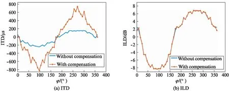
Fig.2 Results of signals without compensation and with compensation
We can see that in Fig.2: 1) The compensated ITD result approximates that of binaural recordings on a dummy head; 2) The ILD results with and without compensation is roughly equal because the time delay filter does not change signal amplitude.
3.2 Experiment
The recording devices as shown in Fig.3 include Sabine panorama microphone[7]and an 8-elements LDMA, spacing 0.011m. The Sabine recording device uses the artificial ear design and the distance between ears is 0.16 m. Binaural recording is used to obtain binaural signals directly, so that we select it as the benchmark device.

Fig.3 Recording devices
We use a 48-elements loudspeaker array to play source audio in a reverberant environment. The recording devices are placed at the center of the loudspeaker array and meet far field condition of the recording. 48 loudspeakers play speech signal one by one in a clockwise direction.
From Fig.4, we can see that: 1) The ITD result of binaural audio with compensation is higher than Sabine; 2) The ILD of Sabine and binaural audio with compensation are not smooth. This is because actual system background is quite noisy.

Fig.4 Results of experiments
We choose 10 testers to score random audio: Sabine, the proposed method without compensation and with compensation. In the testing process, the computer for playing audio, sound volume and headphone are consistent and unchanged. Each tester scores all audio in the following two aspects: sense of orientation and out-of-head experience. And testers are told about the following rating rules:
Sense of orientation: 0—10 point, 0 represents the worst sense of orientation and 10 is optimal. 0—4, 5—7, 8—10 indicate that the sound source distribution is not consistent and the motion track is not smooth, the distribution and the track are relatively smooth, the distribution and the track are smooth, respectively.
Out-of-head experience: 0—10 point, 0 is the weakest and 10 is the strongest. 0—4, 5—7, 8—10 respectively indicate that the sound source is located in the head, on the surface of head, outside the head, respectively, and the motion radius of sound source is smaller than, close to and larger than the size of head. The smaller radius, the lower score.
Testing results are shown in Tab.1. We can see that: 1) For out-of-head performance, binaural audio with compensation is better than Sabine; 2) Binaural audio with compensation can improve the sense of orientation and its source image directions are more accurate; 3) Testers’ perception shows that the source images of Sabine are higher than horizontal plane.

Tab.1 Test results from 10 testers subjective
4 Conclusion
This paper proposes a binaural rendering algorithm using small-sized linear differential microphone array for recording and Ambisonic-based virtual loudspeakers and HRTF knowledge for rendering. It can be demonstrated through experiments that this method realizes immersive binaural rendering and is better than the binaural recording device Sabine in terms of sense of orientation and out-of-head experience.
References:
[1] ZHANG W, PRASANGA S, CHEN H C, et al. Surround by sound: A review of spatial audio recording andreproduction [J].AppliedSciences, 2017,7(5): 532.
[2] ALGAZI V R, DUDA R O. Headphone-based spatial sound [J].SignalProcessingMagazineIEEE, 2011,28(1): 33-42.
[3] BENESTY J, CHEN J D. Study and design of differential microphone arrays [M]. New York,USA: Springer, 2012: 1-31,115-144.
[4] HELLER A, LEE R, BENJAMIN E. Is my decoder Ambisonic[C]∥125th Audio Engineering Society Convention. London, UK: AES, 2008: 1-21.
[5] CHENG C I, WAKEFIELD G H. Introduction to Head-Related Transfer Functions(HRTFs): Representations of HRTFs in time, frequency, and space [J].JournalofAudioEngineeringSociety, 2001,49(4): 231-249.
[6] VALIMAKI V. Discrete-time modeling of acoustic tubes using fractional delay filters [M]. Helsinki, Finland: Helsinki University of Technology, 1995: 65-81.
[7] SABINETEK Inc.全球首款3D全景麦克风[EB/OL].[2018-09-15].http:∥www.sabinetek.com/l,4,0.html.
