Experimental Study and Finite Element Analysis on Ultimate Strength of Dual-Angle Cross Combined Section Under Compression
2019-06-12HaoHuJianHeLianSongZhifengZhanandZhengliangLi
Hao Hu ,Jian He ,Lian SongZhifeng Zhan and Zhengliang Li
Abstract: This paper investigates Q420 dual-angle cross combined section columns under axial and eccentric compression by conducting experiments.The specimen parameters,experimental setup,and test results are presented.It showed that local buckling occurred apparently for single internode specimens(λ<35)under axial compression,while overall bending buckling appeared for others,and no torsional buckling occurred.The theoretical formulas on stability factor were derived by the energy approach.Non-linear finite element models considering residual stress were established using ANSYS which were verified by the corresponding experimental results.The parametric study was to evaluate the effects of slenderness ratio(λ),width to thickness ratio of angles(b/t),the number of filled plate(n),load relative eccentricity(e)and the lateral support stiffness on the ultimate strengths of dual-angle cross combined section columns.Based on above analysis,the design equations are proposed by using curve fitting technique.It is shown from comparison between test results,finite element analysis and related specifications that the ultimate strength from theoretical formulas,proposed equations and finite element models are consistent with experiments results.
Keywords: Double angle,combined section,experimental,finite element analysis.
1 Introduction
Transmission tower line project has played an important role in Chinese economic development with the increase in electric power demand.Moreover,the tower with high-strength combined angle section is urgently needed because the component with low-strength single angle section has been unable to meet the carrying capacity required for high-rising and long-distance tower which suffers more and more complicated loads.The single section has been studied sufficiently at present.Wakabayashi et al.[Wakabayashi and Nonaka(1965)]tested single angle in transmission on the buckling strength and results were compared with buckling theories.Earls et al.[Earls and Galambos(1997);Earls(2001)]studied equal-leg single angle geometric axis flexure and proposed relevant calculation methods by finite element techniques which compared and were agreed well with test results.The response of steel single equal-leg and unequal-leg angles subjected to eccentric compression were investigated by finite element analysis and experimental study by Liu et al.[Liu and Hui(2010);Liu and Chantel(2011)].Wei et al.[Wei,SU,Ma et al.(2012)]researched on the optimal layout of high-strength steel in the ultrahigh voltage transmission towers and the optimization model was solved by using fast non-dominated sorting genetic algorithm.Buckling resistance of perforated hot-rolled steel L-shaped members was investigated using ABAQUS procedure by Brando et al.[Brand and Matteis(2013)].Cao et al.[Cao,Guo and Zeng(2015)]studied buckling behavior of Q420 large-section and high-strength angle steel(LHS)columns under axial compression by test and finite element method,and a new column curve was proposed to predict the buckling strengths of LHS columns.
The buckling behaviors of dual-angle columns were not so much reported despite of wide application in angle-steel transmission tower at home and abroad.The inelastic flexural and flexural-torsional buckling of axially loaded,pin-ended single-angle,tee and double-angle struts(T type)were investigated experimentally theoretically by Kitipornchai et al.[Kitipornchai and Lee(1986)].The evaluation for double-angle members(T type)under flexural-torsion condition based on the AISC specifications was studied by Liu et al.[Liu,Lue and Lin(2013)].Bearing capacity of eccentric compression members with combined angle iron cross-section was research by Li et al.[Li,Yang,Han et al.(2009)].Liu et al.[Liu and Li(2013)]studied dual-angle cross combined section columns of single internode under axial compression by test,and derived theoretical formulas on capacity based on the energy approach.Calculation method of pad connecting two angle steel in transmission steel tower was obtained by Zhong et al.[Zhong and Jin(2008)].However,it maybe update for design theory on dual-angle combined section obtained from solid-web component in Chinese specifications[Zhang,Xia and Huang(2003);He,Wei and Luo(2002)].Design equations in foreign codes[AISC 360-05(1985)and Eurocode 3(2005)]were not completely applicable to Chinese steel columns because of difference on material,standard and manufacture level.The mechanical behavior for plate with crack was investigated based on adaptive singular ES-FEM and poly-tree adaptive ES-PFEM using ANSYS[Nguyen,Liu,Bordas et al.(2013);Nguyen,Nguyen,Rabczuk et al.(2017);Chau,Ngo,Klaus et al.(2018)].All in all,it is necessary to study the behaviors of cross section composed of two high-strength angles with the rapid development of transmission tower.
This research aims to study the buckling behaviors of dual-angle cross combined section columns on single and double internode with different slenderness ratios under axial and eccentric compression by test.Non-linear finite element models considering residual stress were established by ANSYS and agreed well with the test results.Based on verified finite element models,the parametric study was to evaluate the effects of slenderness ratio(λ),width to thickness ratio of angles(b/t),the number and position of batten plate(or called filled plate)(n),load relative eccentricity(e)and the lateral support stiffness on the ultimate strengths of dual-angle cross combined section columns.Finally,the theoretical formulas using the energy approach and proposed equations based on parametric analysis were given,which were consistent with experiments.
2 Experimental work
2.1 Test specimens
The specimens are composed of two kinds of specifications L160×12,L160×14 and the material is Q420,as shown in Fig.1.The experimental columns assembled together by two equal leg angles are bolted by batten plates,which are combined with and without horizontal supports,respectively.The components under eccentric compression generated by load deviation of angles include single and double internode specimens(λ=30~50)which are L14(In Figs.1(a),1(c)and 1(e),where,the symbolOis eccentric load action position,eois load eccentricity which is the distance from this position to the centroid of the cross section measured in the major-axis direction,andρis the distance from the side of leg to the centroid)and S14 series(In Figs.1(b),1(c)and 1(e)),respectively;the others are single internode under axial compression for L12 series(λ=25~55)in Figs.1(a),1(c)and 1(d).The each end of specimen was milled with flat plate to ensure full contact with end bearing plates.The specimen parameters are shown in Tab.1.The material properties obtained from the tensile coupon tests are summarized in Tab.2,which include the elastic modulus(E),the tensile yield stress(fy),the yield strain(εy).
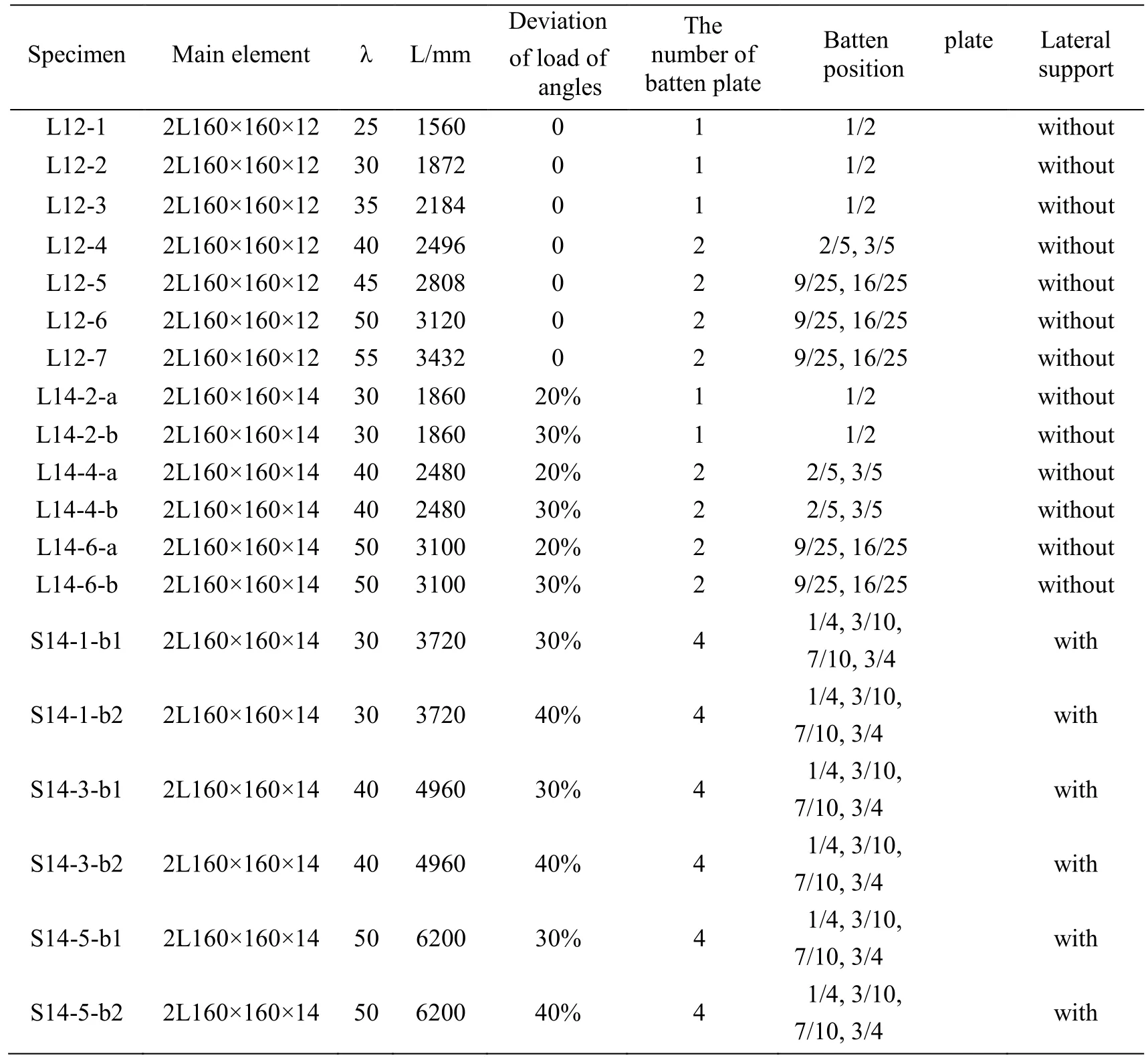
Table 1:The test specimens of dual-angle cross combined section

Table 2:Material properties of steel
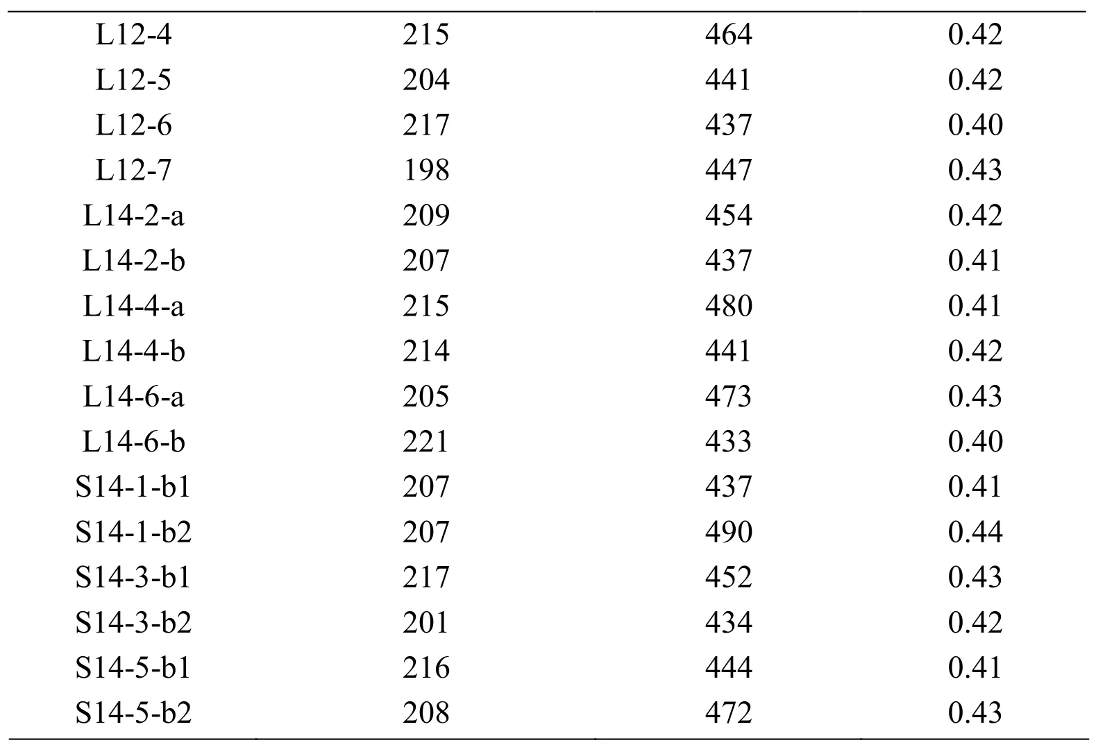
L12-4 215 464 0.42 L12-5 204 441 0.42 L12-6 217 437 0.40 L12-7 198 447 0.43 L14-2-a 209 454 0.42 L14-2-b 207 437 0.41 L14-4-a 215 480 0.41 L14-4-b 214 441 0.42 L14-6-a 205 473 0.43 L14-6-b 221 433 0.40 S14-1-b1 207 437 0.41 S14-1-b2 207 490 0.44 S14-3-b1 217 452 0.43 S14-3-b2 201 434 0.42 S14-5-b1 216 444 0.41 S14-5-b2 208 472 0.43
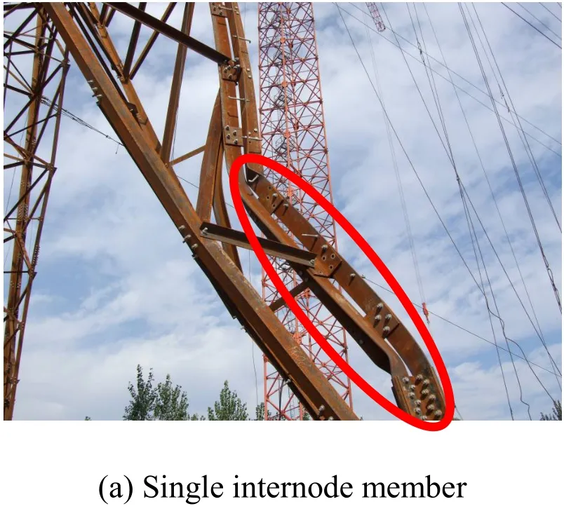
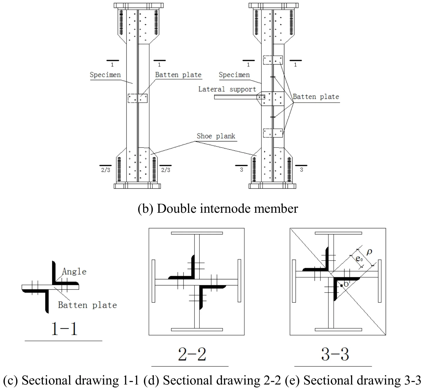
Figure 1:Shape of the specimen
2.2 Test setup and procedure
This loading experiment was conducted in Laboratory on Structural Engineering of Chongqing University.The specimens were loaded vertically by a testing machine 10000 kN capacity.The size of batten plates is 140 mm*306 mm*16 mm and 140 mm*306 mm*18 mm.The specimen ends were bolted by shoe planks which were connected with hinge caps.The hinge support consisted of the hinge cap and ball hinge which was joined by the base.The lateral supports of the double internode specimens were connected with cross beams which were combined by the loaded frame.The force sensors were placed between the lateral support and cross beam,as shown in Fig.2.A theodolite was used to measure the verticality of the specimen before test.At the loaded ends of the specimen,the lateral movements were prevented by four horizontal stopper steel bars with the diameter of 20 mm which were fixed by the loaded frame.The load shortening and lateral displacement were recorded by using the Tokyo-Sokk S-2420 data acquisition system.

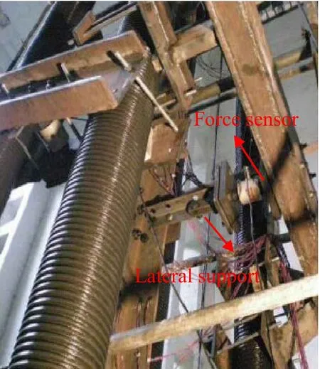
Figure 2:Test setup
2.3 Test result
The failure modes were combined destruction of overall bending buckling and local warping for L12 series specimens which were single internode axial compression members as shown in Fig.3.Local warping of component was more apparent with λ<35,while the failure mode mainly was overall bending buckling with λ≥35.Warping slightly occurred when some specimens with small slenderness ratio value failed,but local instability occurred on one limb of members as long as warping deformation appeared,which led to component failure.

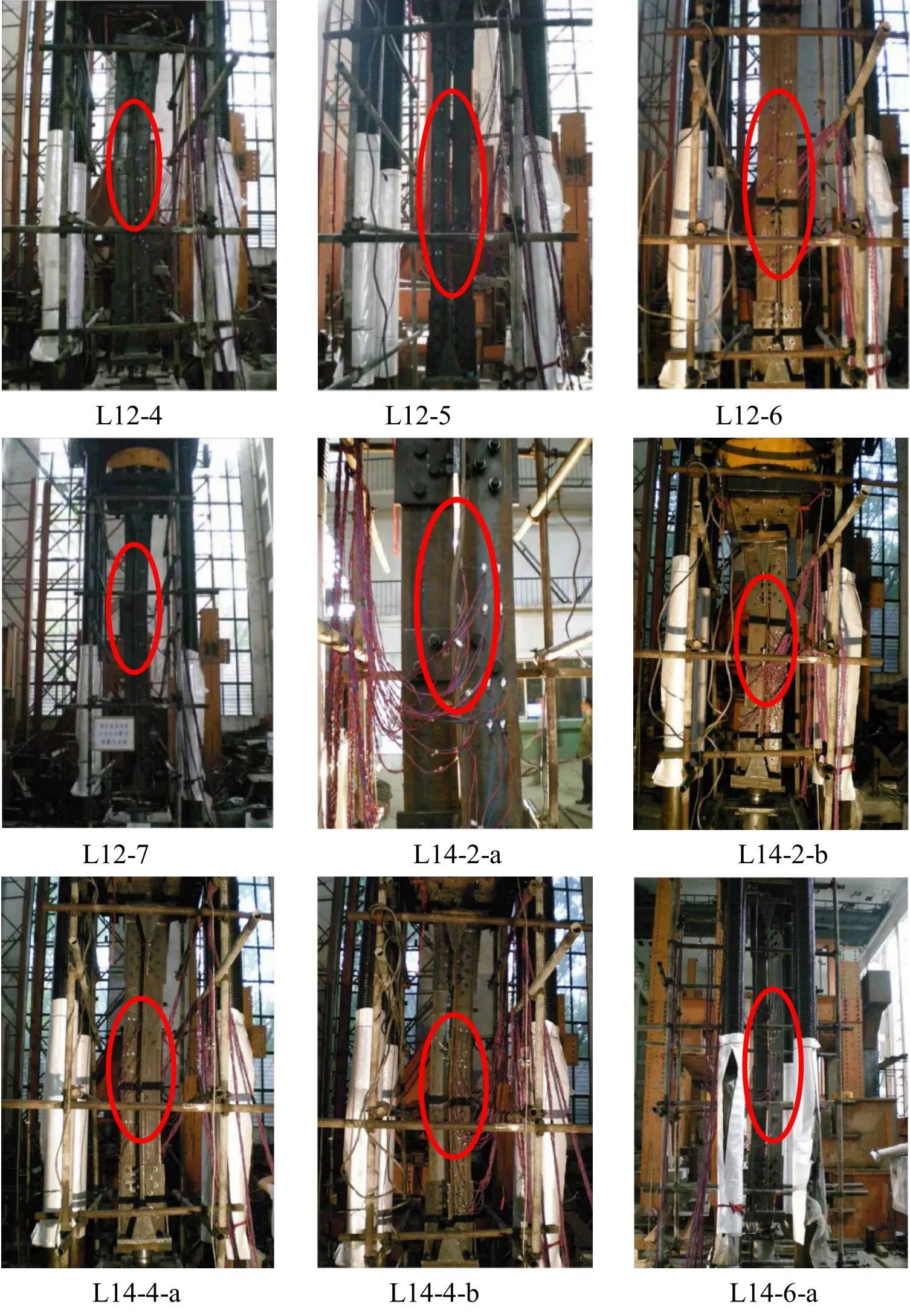
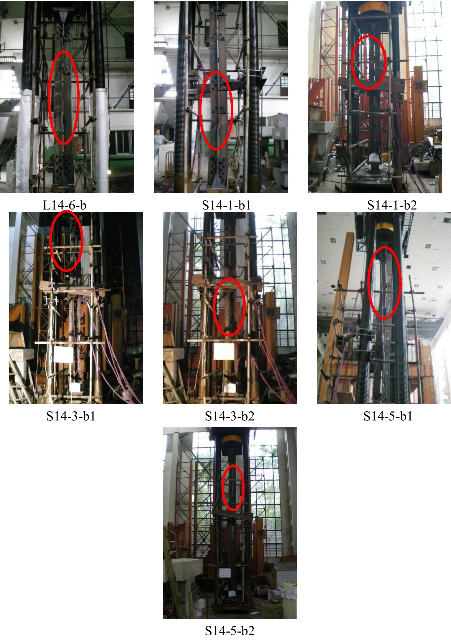
Figure 3:Deformed shapes obtained from test
Apparent warping occurred on the specimens of L12-1 and L12-2 with λ=25 and λ=30,respectively.Initial bending and warping of angles increased with the increase of load value.Local deformation was greater when specimens attained the extreme limit loading and the failure mode of bending appeared.Warping of angles on the specimen of L12-3 with λ=35 was less apparent than the former and overall bending buckling occurred because carrying capacity with big slenderness ratio value was lower than that with small slenderness value.The failure mode was overall bending buckling on the specimens of L12-4 to L12-7 with λ=25 to λ=30,respectively.

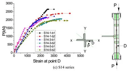
Figure 4:Load-strain curves
The failure mode was overall bending buckling on the specimens of L14 series which were single internode eccentric compression members.Bending buckling in every internode appeared on S14 series specimens which were double internode eccentric compression members.Bending deformation of eccentric compression specimens occurred earlier than that of axial ones.
The experimental load-strain curves of all specimens for same measuring point are shown in Fig.4.It can be seen that the strain value is more than 0.25% and maximum strain is close to 0.5% when specimens failed.The test indicated that the failure mode was overall bending buckling rather than torsional buckling.Rotation of ball joints occurred mainly thanks to bending buckling and local instability of members.
3 The theoretical model
According to the failure modes of specimens in test,simplified mathematical models are shown in Fig.5 and Fig.6.At first,the total potential energy of buckling of plate by the energy method in the slightly curved state was established.The load edges are fixed while it is fixed and free in non-loading sides as shown in Fig.5.The load edges are simply supported and fixed while it is fixed and free in non-loading sides as shown in Fig.6.The total potential energy(II)is the sum of the strain energy(U)and the external potential energy(V)of plate[Liu(1985)].
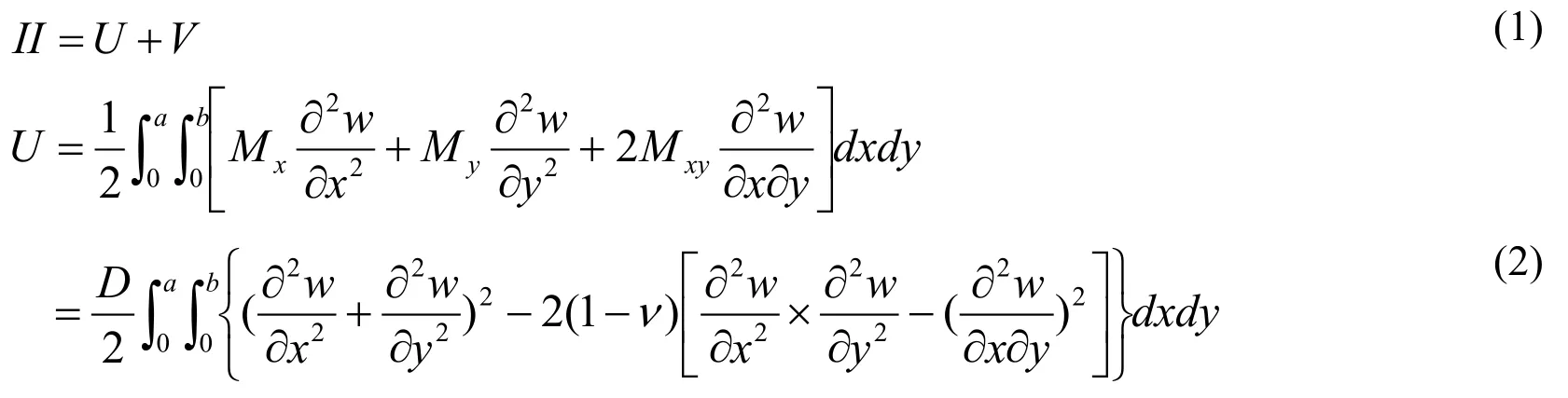

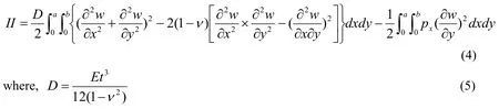
By substitutingpy=0,pxy=0 into(3),the total potential energy(II)is given by
3.1 The number of the filled plate is 1 under axial compression
When the amount of the filled plate is equal to 1 in Fig.5,the deflection surface function of platew,which is consistent with the geometric and mechanical boundary conditions,is assumed as

Substituting Eq.(6)into Eq.(4),the total potential energy(II)is given by


Figure 5:The analysis model with 1 filled plate
According to the principle of stationary potential energy,,the buckling loadis solved by

Because of the arbitrary constantf≠0,Eq.(8)can be simplified to

The buckling load of the plate is obtained whenm=1 andν=0.3.

For the thick angle plate,the buckling will occur in the elastic-plastic state when the buckling stress obtained from the elastic buckling formula exceeds the material proportional limit.

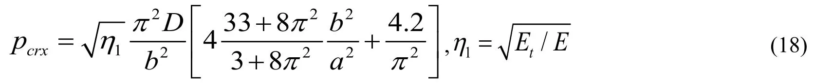
When the local buckling occurs,the buckling capacity of the plate is given by

where,η1-the elasticity modulus reduction factor,
η2-the influence coefficient of local buckling of plate.
3.2 The number of the filled plate is 2 under axial compression
When the amount of the filled plate is equal to 2 in Fig.6,according to boundary conditions of plate,the deflection surface function of platewcan be assumed as

Substituting Eq.(13)into Eq.(4),the total potential energy(II)is given by
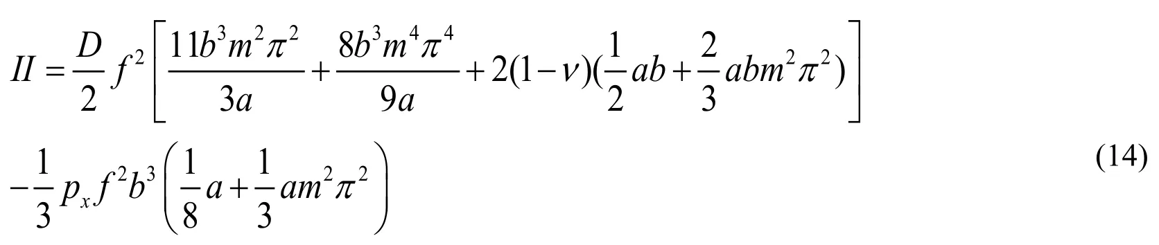

Figure 6:The analysis model with 2 filled plates

Because off≠0,Eq.(15)can be simplified to

The buckling load of the plate can be obtained whenm=1 andν=0.3.

For the thick angle plate,the buckling will occur in the elastic-plastic state when the buckling stress obtained from the elastic buckling formula exceeds the material proportional limit.
When the local buckling occurs,the buckling capacity of the plate is given by

3.3 The number of the filled plate is 1 under eccentric compression
Under pressure and bending moment in Figs.7 and 8,px1is the line load distributed on the surface of plate,andα0is the stress gradient.


Figure 7:The analysis model with 1 filled plate
When the amount of the filled plate is equal to 1 in Fig.7,substituting Eqs.(20)and(6)into Eq.(4),the total potential energy(II)is given by


Because off≠0,the Eq.(22)can be simplified to

The buckling load of the plate can be obtained whenm=1 andν=0.3.

For the thick angle plate,the buckling will occur in the elastic-plastic state when the buckling stress obtained from the elastic buckling formula exceeds the material proportional limit.

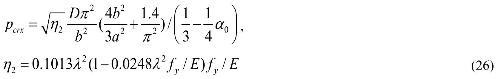
When the local buckling occurs,the buckling capacity of the plate is given by
3.4 The number of the filled plate is 2 under eccentric compression
When the amount of the filled plate is equal to 2 in Fig.8,substituting Eqs.(20)and(13)into Eq.(4)as above.

Figure 8:The analysis model with 2 filled plates


Because off≠0,the Eq.(28)can be simplified to
The buckling load is given whenm=1 andν=0.3 as above.

For the thick angle plate,the buckling will occur in the elastic-plastic state when the buckling stress obtained from the elastic buckling formula exceeds the material proportional limit.

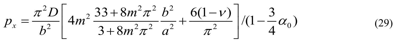
When the plate occurs local buckling,the buckling load is given as above.


Figure 9:Comparison of stability factor obtained from test and theory
The stability factors obtained from the theory calculation and tests are compared in Fig.9 for all specimens.Single and double internode eccentric compression members are simplified as single internode axial ones for calculation.The theoretical value is lower than that of the test mainly owing to two hypothesis of calculation model.The one is that the effect of constraint from the filled plate to angle on bearing capacity of specimens is ignored.The other is that the impact from steel hardening on the carrying capacity is not taken into consideration in the theoretical analysis.However,it can be seen that the change trend is basically consistent with each other.
4 Finite element analysis
4.1 FEA model
Three-dimensional four-node shell element(SHELL181)given in the finite element program ANSYS was used in this study to model the angle,filler plate and end plate;the models of single and double room components were established,as shown in Fig.10.The arc-length method is used in the nonlinear analysis program for components with two ends on simply hinged supports under the loading way as test.Steel constitutive and residual stress distribution are shown in Fig.11.Initial bending of all members was taken into account as the first mode of eigenvalue buckling analysis.The elastic modulus(E),tensile yield stress(fy),yield strain(εy),ultimate tensile stress(fu),ultimate strain(εu)and Poisson's ratio(ν)from tensile steel coupon tests are used in ANSYS.

Figure 10:The finite element model

Figure 11:Steel constitutive and residual stress distribution
The comparison of the member strengths obtained from the finite element analysis and tests is summarized in Tab.3.Good agreement between the FEA and test results was achieved with the maximum difference of 10.5%.The typical failure modes obtained from finite element analysis were verified by that observed in the experimental investigation,as shown in Fig.12.The minor deviation between the FEA and test results attributes to the difference between the ideal FEA model and practical experimental work with inevitable specimen and material imperfections.In general,the failure modes of the specimens observed in the tests were closely simulated by the finite element analysis.Thus,it was shown that the developed finite element model successfully predicted the structural behavior of the dual-angle cross combined section under axial and eccentric compression.

Table 3:Comparison of ultimate strength obtained from tests and FEM

L12-4 2180.00 2326.61 -6.7%L12-5 2200.00 2203.19 -0.2%L12-6 1950.00 2153.87 -10.5%L12-7 1900.00 2044.63 -7.6%L14-2-a 2840.00 2671.59 5.9%L14-2-b 2410.00 2514.11 -4.3%L14-4-a 2490.00 2587.11 -3.9%L14-4-b 2490.00 2429.74 2.4%L14-6-a 2330.00 2431.12 -4.3%L14-6-b 1850.00 2018.35 -9.1%S14-1-b1 2650.00 2585.20 2.4%S14-1-b2 2400.00 2453.80 -2.24%S14-3-b1 2220.00 2366.64 -6.6%S14-3-b2 2070.00 2283.92 -10.3%S14-5-b1 2140.00 2141.12 -0.5%S14-5-b2 1960.00 2098.00 -7.0%
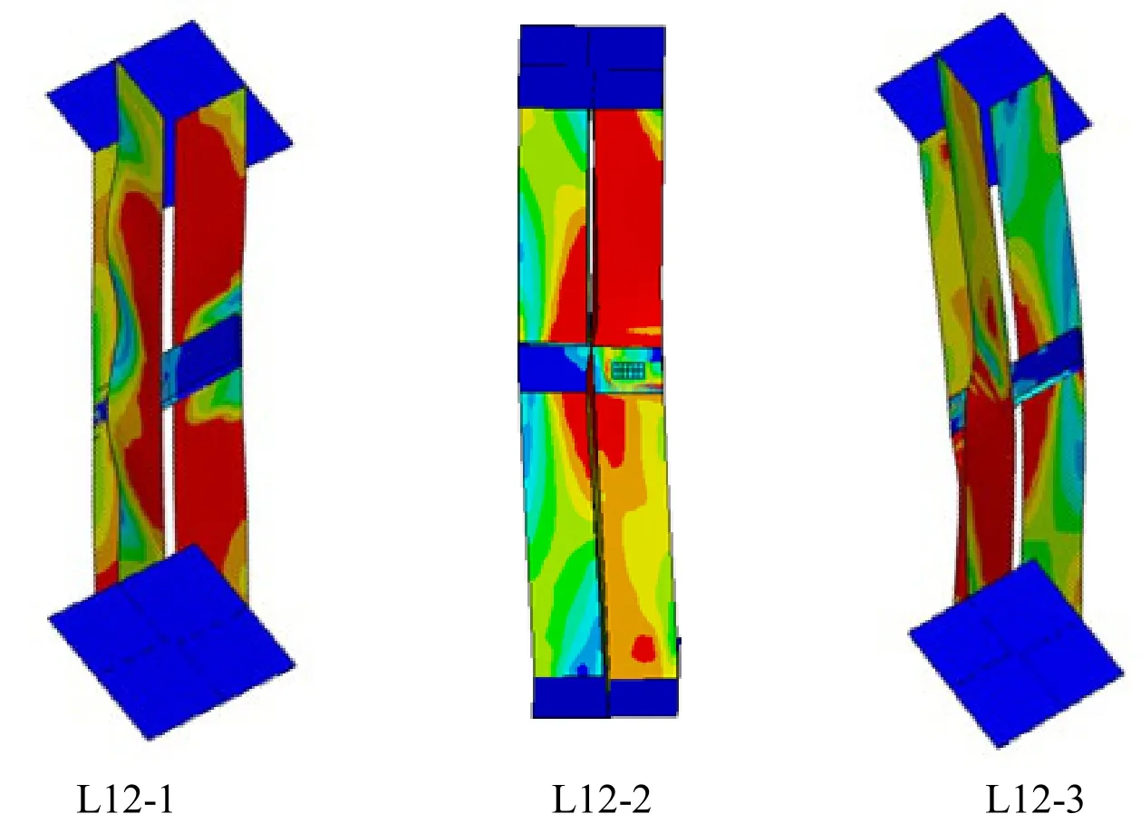
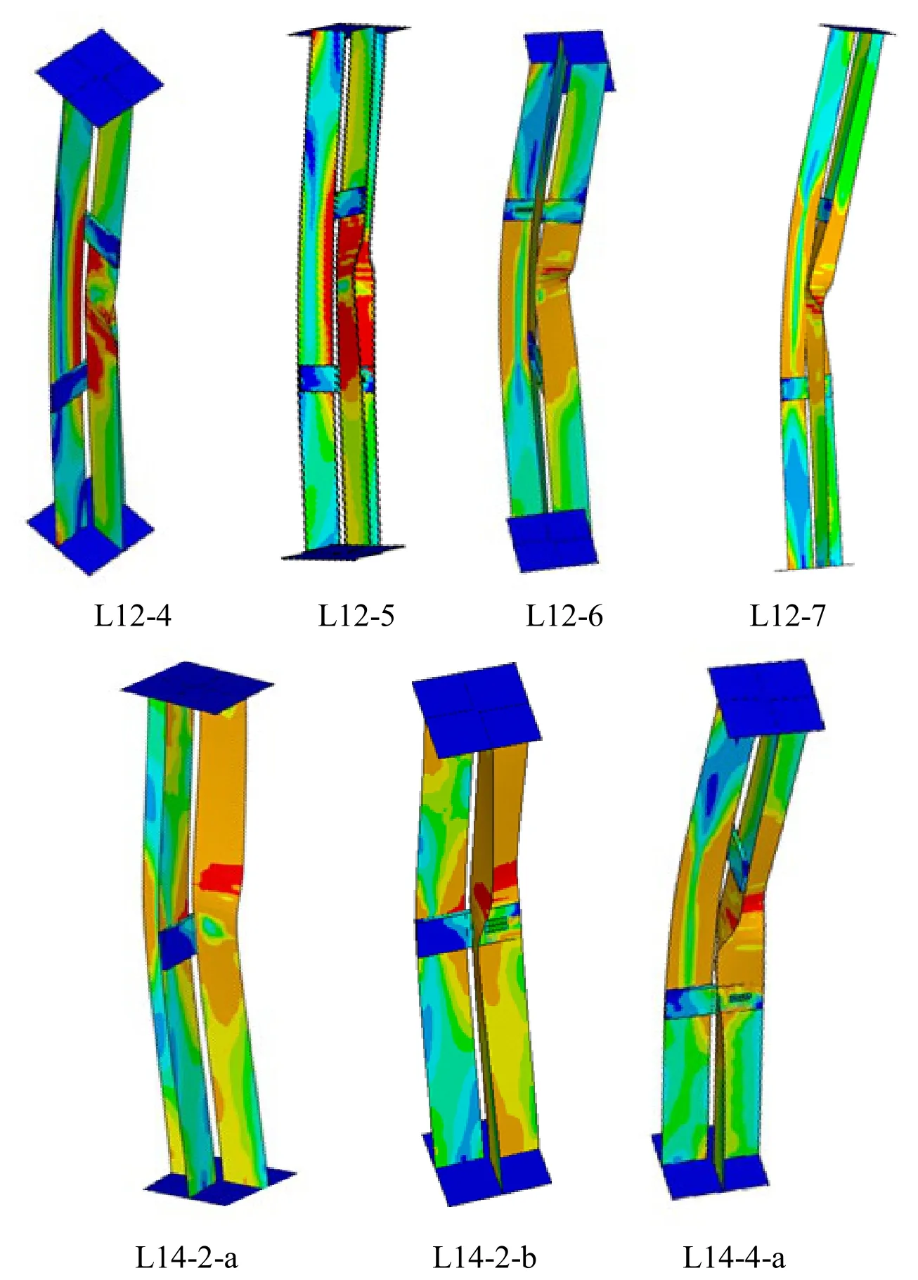


Figure 12:Defomed shapes obtained from FEA
4.2 Effects of geometric parameters
The effects of main geometric parameters on the behavior of members were carefully investigated in the parametric study by FEA,which include slenderness ratio(λ),width to thickness ratio of angles(b/t),the number and position of filled plate(n),load relative eccentricity(e)and the lateral support.

Figure 13:Influence of parameter λ on load-carrying capacity

Figure 14:Influence of width-thickness ratio on load-carrying capacity
As shown in Figs.13 and 14,the effects of parameters(λ,b/t,n)on the carrying capacity of single internode axial compression members were studied,andPyis yield load of specimens,Pis ultimate load.The carrying capacity decreased with the increase ofλandb/tvalue regardless of the number of filled plate in Figs.13(a)and 13(b).The carrying capacity increased stably with the increase ofnandt/bvalue when the filled plate was arranged uniformly in Figs.14(a)and 14(b).
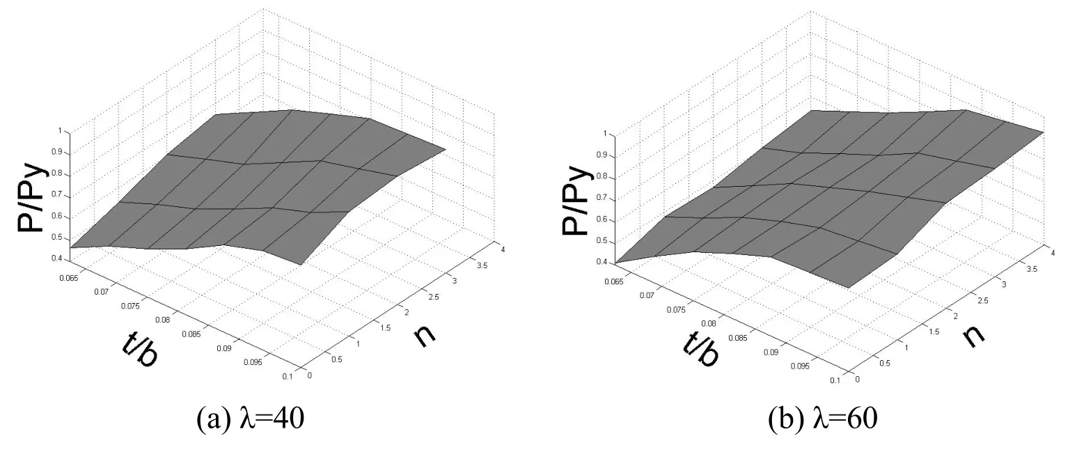
Figure 15:Influence of width-thickness ratio and parameter n on load-carrying capacity

Figure 16:Influence of parameter e on load-carrying capacity
As shown in Figs.15 and 16,the effects of parameters(λ,b/t,n,e)on the carrying capacity of single internode eccentric compression members were studied.PyandMyare yield load and moment of specimens,PandMare ultimate load and moment,respectively.For specimens with fixedλand relative eccentricitye(e=eo/ρ,see Fig.1)value while filled plate distance is less than 40i(the parameteriis the smallest radius of gyration of single angle),the ultimate strengths increased with the increase oft/bandnvalue within a certain range,and then increased slowly asnvalue increased continuously in Figs.15(a)and 15(b).The impacts of relative eccentricityevalue around the weak and strong axis of combined section on the ultimate strengths(b/t=160mm/14mm,n=2)were shown in Figs.16(a)and 16(b),with differentλvalue,respectively.It shows that the trend of change on the ultimate strengths around the weak axis was larger than that around the strong axis when relative eccentricityevalue increased.Therefore,the carrying capacity of members with eccentric compression can be calculated as the ones with axial compression in the range of its changing slowly.

Figure 17:Influence of parameter λ on load-carrying capacity
As shown in Figs.17-23,the effects of every parameter on the carrying capacity of double internode eccentric compression members were studied(e=0 shows axial compression).In Fig.17,the ultimate bearing capacity decreased with the increase ofλvalue on axial and eccentric compression members.It decreased slowly with the increase ofevalue in the case of sameλvalue.In the range of 30 to 80 aboutλvalue,load capacity showed a mean decrease of 12.3% withe=0,and 11.0%,9.2% withe=0.3 ande=0.6 around the weak axis,respectively.At the same time,it showed an average decrease of 11.7%,10.9% withe=0.3 ande=0.6 around the strong axis,respectively.
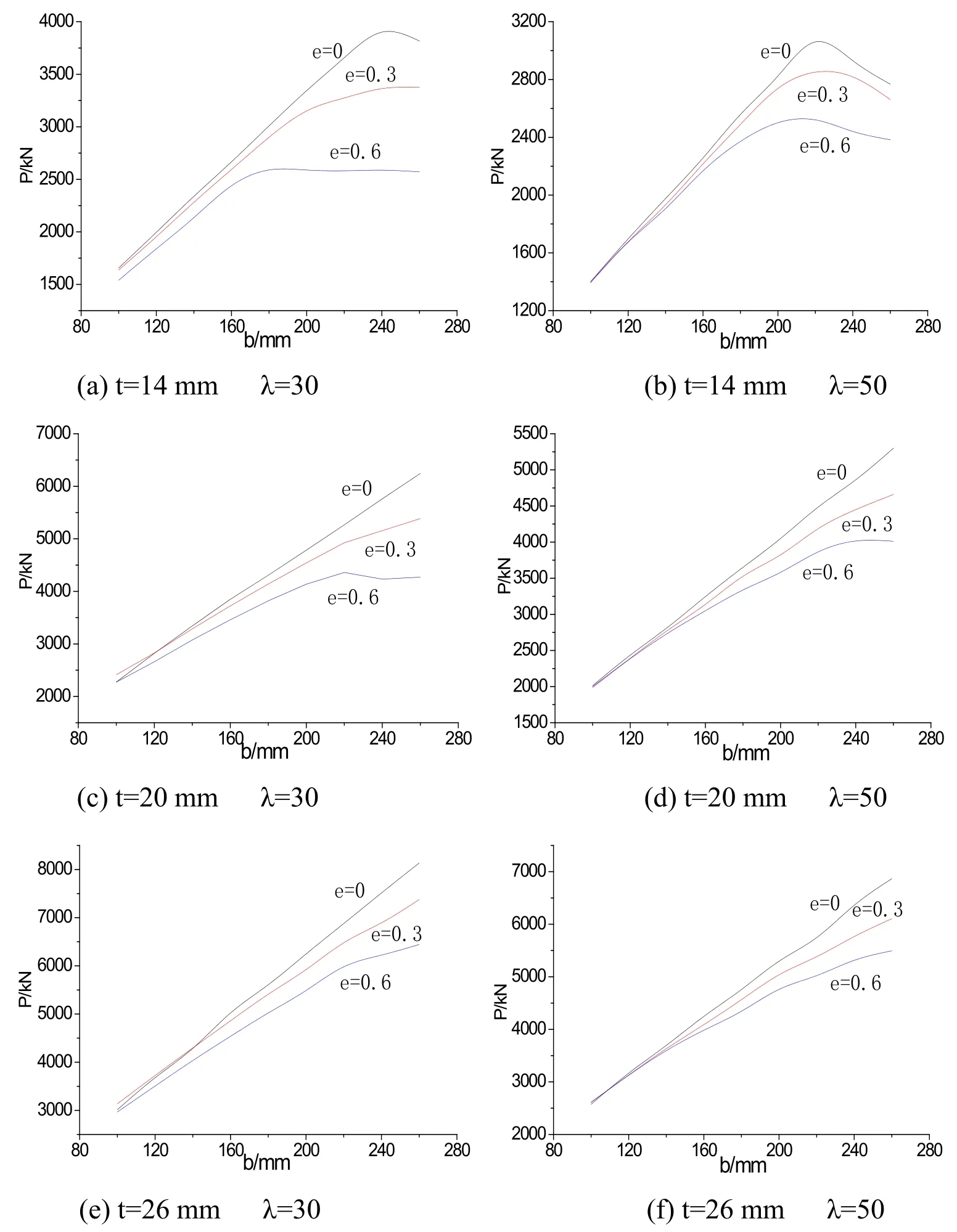
Figure 19:Influence of parameter b on load-carrying capacity(around the strong axis)
In Figs.18 and 19,the effects of the width of anglebon the carrying capacity were investigated with different geometric parameters(t=14,20,26 mm,andλ=30,50)as eccentric load was applied around the weak and strong axis,respectively.As shown in Figs.18(a)and 19(a),it increased with the increase of b value(t=14 mm,andλ=30)and the failure modes are flexural buckling.It decreased because of local buckling on angles whenb/texceeded a certain value(e=0,b/t=17.1;e=0.3,b/t=12.9;e=0.6,b/t=10).Figs.18b and 19b(λ=50)showed the same law as the former two figures(e=0,b/t=15.7;e=0.3,b/t=14.3;e=0.6,b/t=12.9).
In Figs.18(c)-18(f)and 19(c)-19(f),the failure modes are all flexural buckling when the members reached the ultimate carrying capacity in theb/trange of 3.85 to13.The ultimate carrying capacity appeared linear growth with the increase ofbvalue under axial compression,yet it increased slowly whenb/treached a certain value with eccentric compression.
The ultimate carrying capacity has the similar change law between load eccentricity around the weak axis and the strong axis;it is a little higher around the weak axis in the case of the same eccentricity.The bigger eccentricity is,the lower capacity is,the trend of which with small slenderness ratio is more obvious.
Figs.20 and 21 showed the impact of the number of the filled platenon the ultimate carrying capacity.The Chinese design code requirement[Zhang,Xia and Huang(2003);He,Wei and Luo(2002)]is that the filled plate distance is less than 40i(the parameteriis the smallest radius of gyration of single angle)for dual-angle compression members combined by the filled plate,but it doesn't tell the influence degree of filled plate number on the ultimate strength.The bearing capacity increased with the appropriate increase of the filling plate because of reducing the slenderness ratio and strengthening connection between angles.However,it had a trend of slow increase when the number of filling plate continued to increase because the local bucking deformation between filling plates was too large.Therefore,the filling plate distance was proposed not less than 15iin this study based on the FEA results.
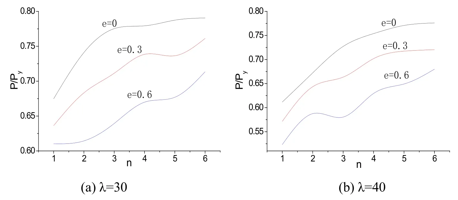
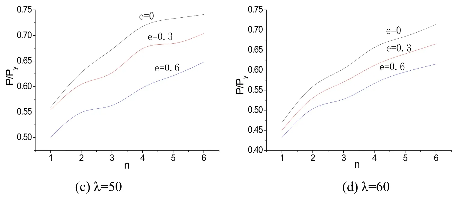
Figure 20:Influence of parameter n on load-carrying capacity(around the weak axis)
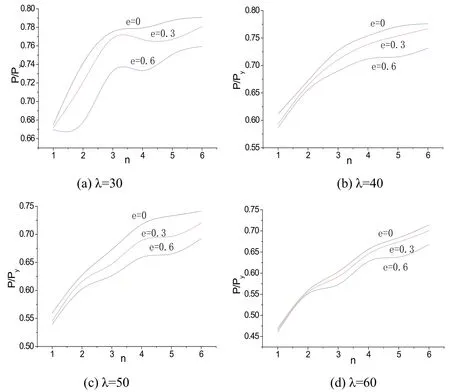
Figure 21:Influence of parameter n on load-carrying capacity(around the strong axis)
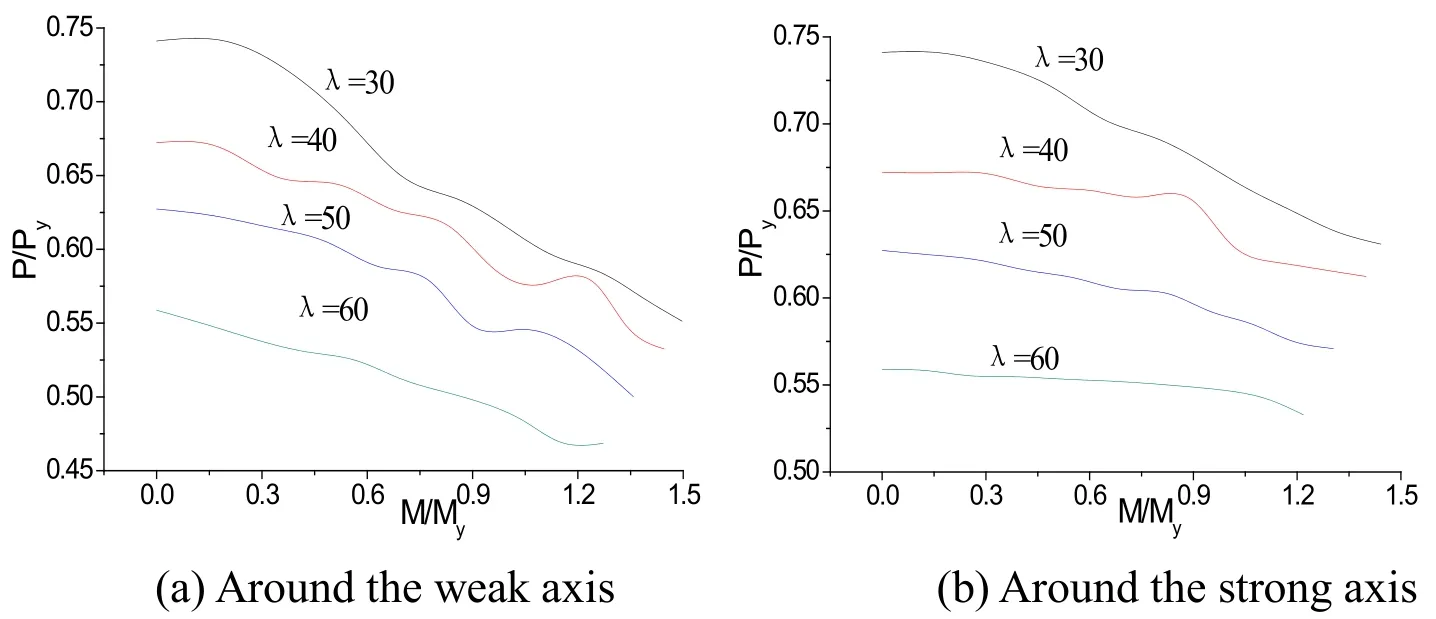
Figure 22:Influence of parameter e on load-carrying capacity
The impacts of load eccentricity around the weak and strong axis of combined section on the ultimate strengths(λ=30~60)of double internode were shown in Fig.22,respectively.It was the decrease trend on the ultimate strengths with the increase ofM/Myvalue.The decrease amplitude was larger around the weak axis than that around the strong axis,and it was the same for members with small slenderness ratio than that with big slenderness ratio.
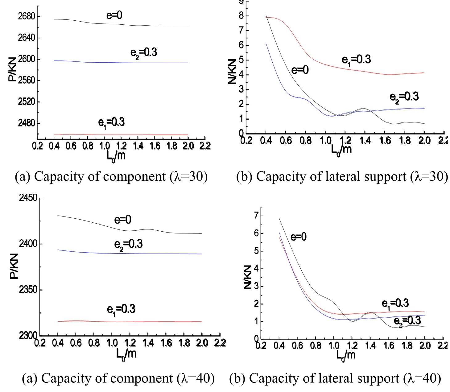
Figure 23:Influence of lateral support rigidity on load-carrying capacity
In Fig.23,the impacts of lateral support on the axial and eccentric members were studied(λ=30,40),L0is the support length,Nis the support load,and the support stiffness is changed by different support lengths;e1is the relative eccentricity around the weak axis ande2is relative eccentricity around the strong axis.The Fig.23 showed that the support stiffness had no influence on the carrying capacity of members.However,the support load decreased with the increase of the support length because of the support stiffness and restriction effect on component reducing.The lateral support had some unchanged internal force whenL0value is more than 1.2 meters due to very weak support stiffness.The support load was less than 0.5 percent of ultimate bearing capacity of all calculated members;it was much lower than that of the current design codes[Zhang,Xia and Huang(2003);He,Wei and Luo(2002)],so the lateral support can be calculated as the Chinese codes.
4.3 Comparison of ultimate strengths of single and double internode component
It was found that the bearing capacity of double internode component under compression in a single room with fixed slenderness ratio was usually lower than that of single one,the trend of which increased with the increase of slenderness ratio based on the finite element analysis.To investigate this trend quantitatively,a total of 98 Q420 models(the number of single and double internode models is equal)under axial compression with different geometric parameters(λ=25~55,b=160 mm,andt=10~16 mm)were analyzed in the parametric study,which were selected from the range of practical applications.Ratio on ultimate strengths of single to double internode component from FEA and ratio on ultimate strengths of double internode component of design code[Zhang,Xia and Huang(2003)]to FEA were shown in Tab.4 and Tab.5,respectively.

Table 4:Ratio on ultimate strengths of single to double internode component from FEA
The capacity obtained from FEA of single internode component is 12.1% higher than that of double on average whose maximum is 17.6% in a single internode withλ=40;it is 31.6% higher withλ=55 on average,and the maximum is 37.4% as shown in Tab.4.
The capacity obtained from code[Zhang,Xia and Huang(2003)]is 8.8% higher that from FEA on average on double internode models and the maximum is 13.6% withλ=35;it is 16.4% higher withλ=40 on average and the maximum is 19.2%;it is 34.3% higher withλ=55 and the maximum up to 38% as shown in Tab.5.The capacity calculated from the code for design of steel structures is equal between single and double internode components with the same slenderness ratio value and other same parameters.
If the maximum difference of 10% was acceptable,the slenderness ratio value recommended on double internode components was less than 40 in a single internode based on comprehensive FEA and specification results.
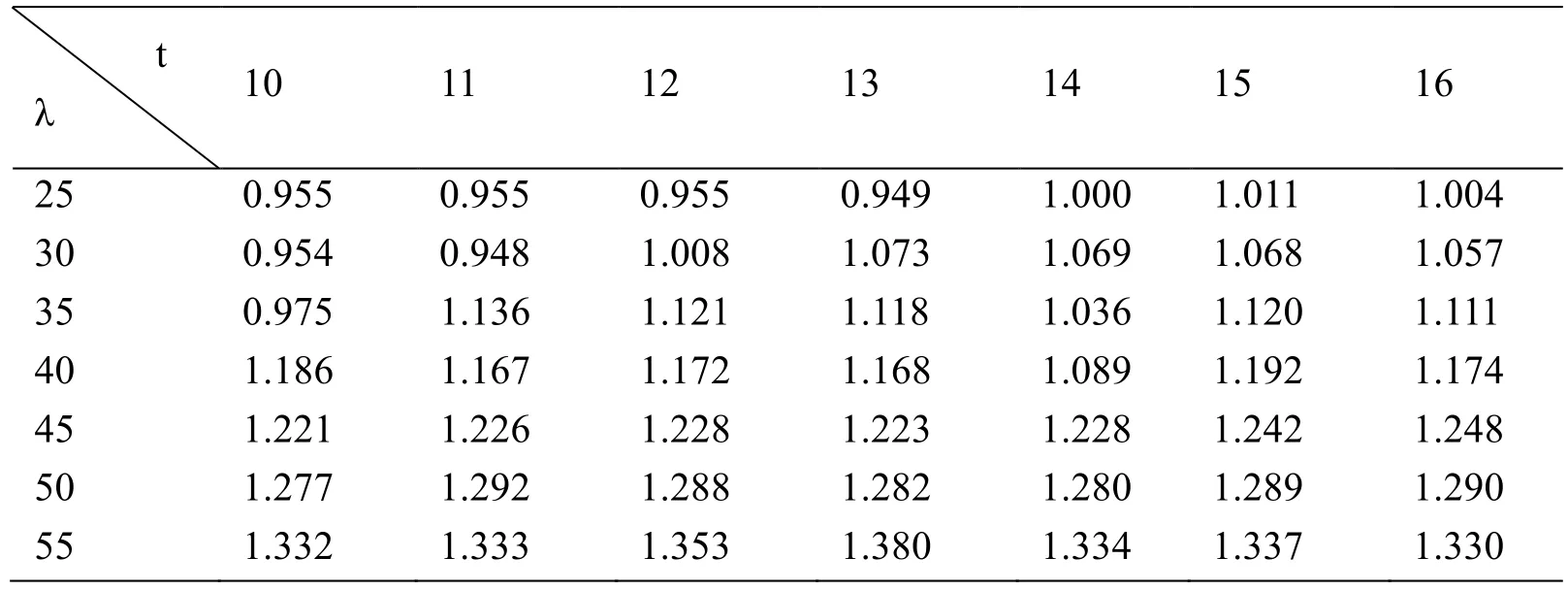
Table 5:Ratio on ultimate strengths of double internode component of design code to FEA
5 The Proposed formulas
The design formulas are proposed in this study based on the FEA results using curve fitting technique for single and double internode components under axial and eccentric compression subjected to different failure modes as follows.
5.1 The single internode component under axial compression
Based on the above discussions and analysis,with some appropriate amendments to the calculation method of lattice component in code[Zhang,Xia and Huang(2003)],the calculate results can be in good agreement with the test value of stability capacity of double-angle cross section member.If the double-angle cross section component was looked like a lattice one based on steel design code[Zhang,Xia and Huang(2003)],the bearing capacity should be modified by multiplying a coefficientξconsidering the slenderness ratio,and the total formula is still as follow:

But the slenderness ratio of combined section should be instead of the equivalent slenderness ratio.

Therefore,the slenderness ratio of dual-angle cross combined section is given by

where,
φ-stability factor;
f-design strength value of steel;
A-area of combined section;
λ0-equivalent slenderness ratio;
λx-slenderness ratio of the entire component;
λ1-slenderness ratio around the smallest sub-limb stiffness axis,whose effective length is the distance of bolts between consecutive two filled plates;
ξ-adjustment factor.
The adjustment factor is as follow:

The parameters are as follows:
a0=2164.0-378.2275*(b/t)+16.3538*(b/t)2
a1=-15473.5+2712.6475*(b/t)-117.5318*(b/t)2
a2=40473.4-7111.34*(b/t)+308.679*(b/t)2
a3=-45828.2+8070.0925*(b/t)-350.9153*(b/t)2
a4=18999.1-3353.05*(b/t)+146.055*(b/t)2
-dimensionless slenderness ratio,;
fy-yield strength value of steel;
E-elastic modulus of steel;
b-limb wide of angle iron;
t-thickness of angle iron.
5.2 The single internode component under eccentric compression
In practical engineering,the combined action of bending moment and axial force leads to complex loading of members.The relationship between the two former was discussed,which gave the recommended formula on the bearing capacity of members with evenly arranged filling-plate(n=1,2)and eccentric around different axis.It was chosen in the range of 25 to 60 as the common slenderness ratio of the main member in transmission tower should not be too big.
When the amount of the filled plate is equal to 1:

Around the weak axis,
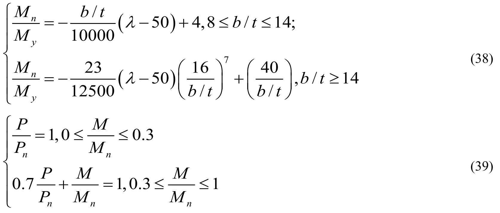
Around the strong axis,

When the amount of the filled plate is equal to 2:

mN-bar stability strength reduction factor.
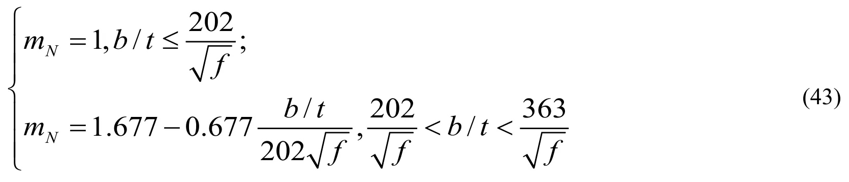
Around the weak axis,

Around the strong axis,
Pn-ultimate bearing capacity of component for axial compression;
Mn-moment of section(when relative eccentricityeis 1)when the component reaches
ultimate bearing capacity;
Py,Myand other parameters are as above.
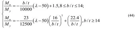
5.3 The double internode component under eccentric compression
The design equations of double internode component for eccentric compression were proposed in this part;the slenderness ratio chosen was in the range of 30 to 60.The filled plates in every room and the lateral supports were set up as regulatory requirements[Zhang,Xia and Huang(2003)].ALL parameters are as above.

Table 6:Comparison between code and formula for capacity of component
The capacity results of specimens obtained from different methods are given in Tab.6 and Fig.24.PGB1andPGB2are the results calculated from the code[Zhang,Xia and Huang(2003)]with different yield stress(the nominal yield strength and material test yield strength),andPDL/Tis calculated from technical regulation[He,Wei and Luo(2002)],PAISCfrom the code[AISC 360-05(1985)],PEC3from the code[Eurocode 3(2005)]andPREfrom the proposed formulas,respectively.However,the relevant calculation methods on dual-angle cross combined section with double internode are not given in the codes[AISC 360-05(1985)]and[Eurocode 3(2005)].

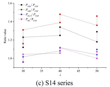
Figure 24:Comparison of the ratio value of Load-carrying capacity for specimens
The ratio value ofPGB1/PEXP,PGB2/PEXP,PDLT/PEXP,PAISC/PEXP,PEC3/PEXPandPRE/PEXPis 1.049,1.129,1.132,1.165,1.066 and 1.027 on average,and the maximum difference is 1.120,1.250,1.228,high to 1.264,1.133 and 1.119 on L12 series,respectively.The ratio value ofPGB1/PEXP,PGB2/PEXP,PDLT/PEXPandPRE/PEXPis 1.158,high to 1.30,1.035 and 0.92 on average,and the maximum difference is 1.370,high to 1.550,1.203 and 0.916 on L14 series,respectively;it is 1.258,high to 1.36,1.052 and 1.041 on average,and the maximum difference is high to 1.340,1.480,1.117 and 1.113 on S14 series,respectively.
By comparison as above,the difference between proposed formulas and test results is the minimum on all specimens because the double internode component calculated by Chinese codes[Zhang,Xia and Huang(2003);He,Wei and Luo(2002)]is just simplified to single internode,moreover,it is equivalent to solid-web component ignoring filled plates.These suggested formulas are given with some safety surplus for bearing capacity design,so proposed estimation underestimate the maximum load for most specimens.However,some proposed estimation values of the components are a little greater than that of experimental results.The ratio value is within 10% and it is acceptable for engineering design.Therefore,it is demonstrated that the proposed method agreed well with test results,which takes account into the material yield strength,cross-section slenderness,filled plate spacing and other factors on stability capacity of composite members,is practical and accurate.
6 Conclusions
The scope of application of relevant code was investigated by component tests because the ultimate bearing capacity of dual-angle cross combined section under compression obtained in the test on 1:1 model tower was inconsistent with that of the current codes[Zhang,Xia and Huang(2003);He,Wei and Luo(2002)].In this test,the specimens were composed of two specifications L160×12,L160×14 and the material was Q420,which included material test,single internode components under axial and eccentric compression,and double internode components under eccentric compression.Based on the experimental and FEA results,the conclusions are as follows:
(1)Apparent local buckling occurs(λ<35)because of small slenderness ratio and filled plates distance;the members with big slenderness ratio show overall bending buckling accompanied by local instability of angle iron.The failure mode is overall bending buckling around the strong axis of cross combined section rather than torsional buckling.Moreover,bending buckling on double internode members appears in every internode and the internode deformation is more apparent near the loading end.
(2)The main geometric parameters which include slenderness ratio(λ),width-thickness ratio of angles(b/t)and load eccentricity(eo)have important effects on the behavior of members.The ultimate bearing capacity decreases with the increase ofλandb/tvalue in the same conditions.The bigger eccentricity is,the lower capacity is,the trend of which with small slenderness ratio is more obvious.However,the lateral support has no influence on components.
(3)The ultimate bearing capacity maybe decrease with the increase of the number of filled plate,especially for components with bigb/tand smallλvalue,in other words,the filled plate distance should not be too small.However,it can increase with the increase of the number of filled plate with bigλvalue.It had a trend of slow increase when the filling plate continued to increase because the local bucking deformation between filling plates was too large.Therefore,the filling plate distance is proposed for not less than 15ibased on the FEA results.
(4)The theoretical formula of dual-angle cross combined section under compression derived shows that it is not only effected by limb wide and thickness of angle iron but also filled plate or batten plate.It is shown from the comparison that the component strengths calculated using the theoretical equations were agreed well with the test results,which simplified complex stress state of members and can provide theoretical basis for practical engineering.
(5)The design equations for single and double internode members under compression are proposed base on comprehensive parametric analysis.Code methods used for traditional method makes calculating results have large error compared with tests,while the design equations agree well,which means the proposed design equations are verified to be accurate and have some applicable value.
Conflict of interests:The authors declare no conflict of interest.
Acknowledgments:This research was financially supported by the science and technology project of Chongqing University of Arts and Sciences(No.2017RJJ31,No.2017YJJ54,No.2017YJJ55),and the major breeding project of Chongqing University of Arts and Sciences(No.P2018JG13).
Data Availability statement:The data used to support the findings of this study are included within the article.
杂志排行

Computer Modeling In Engineering&Sciences的其它文章
- An Automated Approach to Generate Test Cases From Use Case Description Model
- Hybrid Deep VGG-NET Convolutional Classifier for Video Smoke Detection
- A Normal Contact Stiffness Model of Joint Surface Based on Fractal Theory
- Design of Smith Predictor Based Fractional Controller for Higher Order Time Delay Process
- IoT Based Approach in a Power System Network for Optimizing Distributed Generation Parameters
- 3D Bounding Box Proposal for on-Street Parking Space Status Sensing in Real World Conditions