Experimental investigation on flow characteristics in circular tube inserted with rotor-assembled strand using PIV☆
2019-02-15LichenHeWeiminYangChangfengGuanHuaYanLinZhengXiahuaZuo
Lichen He,Weimin Yang,Changfeng Guan,Hua Yan*,Lin Zheng,Xiahua Zuo
College of Mechanical and Electrical Engineering,Beijing University of Chemical Technology,Beijing 100029,China
Keywords:Particle image velocimetry(PIV)Swirling flow Rotor-assembled strand Circular tube
ABSTRACT Rotor-assembled strand works as a typicaltube insert to achieve heat transfer augmentation and scale inhibition in a heat exchanger.In this work,the PIV experiment regarding the flow fields in a circular tube inserted with rotor-assembled strand was conducted and the flow characteristics on transverse section and longitudinal section were analyzed.The results showed that swirling flow was produced in the tube inserted with rotors and it was particularly strong within the swing diameter of the rotor on the section that contains the rotor;the average turbulence intensity and the radial velocity were improved notably;the velocity vectors on the longitudinal section remained along the direction of a straight line;both the swirling flow and average turbulence intensity were higher for the rotor with three blades than for the rotor with two blades except that the radial velocity was approximate,but they were all reduced by enlarging the lead of the rotor.Characterization of the flow patterns in a circular tube contributes to understanding the heat transfer efficiency and scale inhibition performance of the rotor-assembled strand and provides guidance for its application.
1.Introduction
The sustainable development road of energy conservation and consumption reduction must be taken by the nations in the world to keep competitive in the development of economy and society under the background of energy shortage and deficiency.As one kind of high energy consuming equipment,shell and tube heat exchangers are extensively applied in fields of chemical production,petroleum refinery,power generation and metallurgy,and so on.However,the inferior heattransfer efficiency,which causes the loss oflarge amountofenergy,has been the intractable problem disturbing enterprises and even industries.Therefore,it is no time to delay to save energy and improve the energy utilization efficiency.
The heat transfer enhancement technology is just an effective approach to resolve the problem of lower energy utilization efficiency.Heat transfer enhancement techniques can be classified either as passive,which require no direct application of external power,or as active,which require external power[1,2].In comparison to the active techniques,the passive ones are applied more widely in engineering.A variety of passive techniques have been developed,among which the tube inserts are the most popular ones,this is because they can be installed and taken down with ease in existing tube bundles during the routine maintenance without the need for replacing them.The tube inserts consist of several common types:wire coil[3–5],static mixer[6],vortex generator[7–9]and twisted tape[10–14].
Rotor-assembled strand,which is shown in Fig.1,was proposed as a novel kind of tube insert that possesses the functions of heat transfer augmentation and scale prevention by Yang et al.[15]in 2005.With regard to the rotor-assembled strand,lots of research has been conducted.Han et al.[16]described experimental investigation of heat transfer and single-phase pressure drop through tubes with different rotor-assembled strands inserted in the Reynolds number range of 800–9000 with lubricant as working fluid.The comparison of different rotor-assembled strand inserted tubes and plain tube showed that the heat transfer benefited from the increase of the diameter of rotorassembled strand with the same lead and the decrease of the lead of rotor-assembled strand,so does the friction factor.Zhang et al.[17]carried out numerical simulations to investigate the heat transfer and friction loss characteristics of a circular tube equipped with helical blade rotors and to optimize the configuration of the rotor.The simulation results revealed that for rotors with different cross section shapes,the rotor with ellipse section shape generated higher Nusselt number,friction factor and thermal performance factor;for rotors with different axis diameters,the Nusselt number,friction factor and thermal performance factor increased with the increasing rotor axis diameter;for rotors with different blade numbers,the Nusselt number and thermal performance factor increased with the increasing blade number,and the rotor with four blade numbers offered the highest friction factor followed by the rotor with two blade numbers and then the rotor with three blade numbers.Jiang et al.[18]experimentally studied the turbulent heat transfer and flow characteristics in a circular tube equipped with single spiral slot rotor(SSR)-assembled strand,single low flow resistance rotor(LFR)-assembled strand and rotor-assembled strands mixed by spiral slot rotor(SSR)and low flow resistance rotor(LFR).The obtained results revealed that mixed-rotor assembled strand with numberratio Y=2 yielded highermean thermalperformance factor than those with other number ratios Y=1 and 0.5 around 2.83%and 1.64%,respectively and the thermal performance factor decreased with increasing total number(H)of rotors in each group when number ratio is at a constant value Y=2.Zhang et al.[19]reported the thermohydraulic characteristics ofthe circular tube equipped with Left–Righthelicalblade rotors and investigated the in fluence ofthe assembled mode of Left–Righthelicalblade rotors on heattransfer,friction factor and thermal performance factor characteristics of the enhanced tube.The experimental results revealed that the thermal performance factor of Left–Right helical blade rotors increased with the decreasing number of the Right helical blade rotor;meanwhile,the enhanced tube with the ratio of Left–Right helical blade rotor number as 1/3 generated the highest thermal performance factor.

Fig.1.Schematic diagram of rotor-assembled strand.
The hydraulic and thermal performance of the inserts is fundamentally determined by their flow behaviors generated in a circular tube,so itisofgreatimportance to carry outthe research on the flowbehavior.Recently,the visualization measure technique-particle image velocimetry(PIV)is increasingly maturing together with the advancement of optical technology and image processing technology,and it has been extensively applied in various research on flow patterns.Jasiński[20]presented results of the computer simulations of the flow in a circular pipe with ball inserts turbulizing the flow and also the experimental investigations carried out using a PIV apparatus.The obtained results showed a good correlation between the experiment and computer modeling.Song et al.[21]conducted measurements of the flow field in a pipe with twisted tape by PIV.The results revealed the characteristic two-peak velocity profile.Che et al.[22]investigated the characteristics of the longitudinal vortex induced by trapezoid-winglets in a circular tube by the PIV technique.The results showed thata counter-rotating vortex pair was formed behind each wingletand they distributed as a symmetricalvortex array in the transverse section,and the trapezoid winglet showed the preferable turbulent disturbance characteristics in the tube.
As for the PIV investigation on the flow behaviors in a circular tube inserted with rotor-assembled strand,He et al.[23]had already made some attempts.Restricted by the poor conditions in former studies,the crucial flow characteristics on the transverse section are not revealed.For this purpose,in this work the experimental apparatus is redesigned and the experiment is further conducted so that the de ficiency of the former work can be made up for to have a thorough understanding of the flow behaviors in a circular tube inserted with rotor-assembled strand.
2.Experimental
The PIV experiment was carried out in a closed circulation loop,and the schematic diagram and the practical picture of the experimental setup are shown in Figs.2 and 3,respectively.It is composed of a water tank,a pump,a valve,a turbine flowmeter,a quartz glass tube,acrylic tubes,auxiliary PVC tubes and flanges.The flow rate of the circulation loop is controlled by regulating the opening of the valve and its value is measured by the turbine flowmeter.To accurately capture the flow field of the interested zones,the quartz glass tube,which has high quality of light transmission,is selected to be the test section tube,and its dimensions is φ40× 3 mm;also a rectangular transparent box filled with water is fixed outside the quartz glass tube so that the light scattering can be eliminated when the laser is irradiated onto the hook face.The rotor-assembled strand is inserted in the test section tube,and the transverse section and the longitudinal section which need to be captured are shown in Fig.4.
The rotors employed in this experiment,which are shown in Fig.5,are manufactured by 3D printing with the material of photosensitive resin so that the laser can easily penetrate the rotors.The detailed geometrical parameters of the rotors are listed in Table 1.

Fig.2.Schematic diagram of the experimental setup.

Fig.3.Practical experimental setup.

Fig.4.Schematic drawing of test section.
The PIVsystem is a commercialsystem(TSIIncorporated,USA)which includes a laser source(New Wave Research Solo Nd:YAG,200 mJ,15 Hz),a CCDcamera(PowerView Plus 11MP,4008×2672 pixels),a synchronizer and Insight 3G software.The glass bead,which has a diameter of 8–12 μm and possesses good property of light re flection,is selected as the tracking particle.The position and the focus ofthe CCDcamera are adjusted well to acquire a clear field of view.The physical size of the field of view for the transverse section is 34 mm×34 mm,and for the longitudinal section it is 34 mm×100 mm.Based on the dimension of the inner diameter of the tube,the spatial resolutions for the transverse section and longitudinal section are determined to be 41.72 μm·pixel-1and 43.98 μm·pixel-1,respectively.The flow field was consecutively illuminated twice by the laser pulse with tiny time interval Δt,meanwhile it was captured by the CCD camera with the synergy of the synchronizer to acquire a pair of images which record the motion of the tracking particles.The time interval Δt is confirmed by the rule that the maximum displacements of the tracking particles are less than one-quarter of the interrogation window size within Δt,and it is determined to be 450 μs in this experimentaccording to the volume flow rate 30 L·min-1.The interrogation window size is 32×32 pixels with 50%×50%overlap.The number of tracking particles is adjusted to be 5–10 in each interrogation window.When the image pairs are 200,the deviation ofthe RMS velocity is less than 2%and the acquired results are credible,therefore 200 pairs of images are captured for each condition to get the time-averaged velocity field.The Insight 3G software is adopted for processing each pair of images with the cross-correlation algorithm to create a 2D velocity vector map.
3.Results and Discussion
3.1.Parameter definition
The transverse velocity usin the transverse section is defined as:

where,urand uθdenote the radial and tangential velocities in the transverse section,respectively.
The turbulent intensity I in the transverse section is defined as:
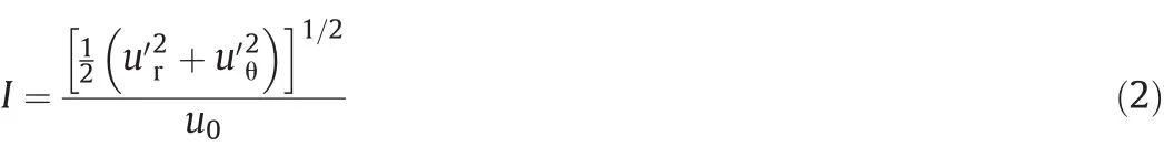
where,ur′and uθ′denote the radial and tangential fluctuating velocities in the transverse section,respectively.
The velocities and the radial position in this work are nondimensionalized with the average velocity of the mainstream u0and the radius of the tube R0,respectively.
3.2.The flow fields on transverse sections

Fig.5.The rotors employed in the experiment.

Table 1 Geometrical parameters of the rotors
Fig.6 shows the velocity fields on transverse sections in the tube with rotor I and plain tube.Transverse velocity integrates the radial and tangential velocity,and it is a quantity that best illustrates the motion of fluid on the transverse section.It can be seen from Fig.6(a)and(c)that swirling flow is produced on section S1 in the tube with rotor I compared with the flow field in the plain tube,and the swirling flow is particularly strong within the swing diameter of rotor I,this is because rotor I rotates under the impact of fluid,and when it rotates,it drives the fluid adhered to the blades to follow its rotation;while in the zone outside of the swing diameter of rotor I,the swirling flow is relatively weak.By comparison,it can be obtained thatthe maximumvalue of us/u0on section S1 in the tube with rotor I is 596.8%higher than that in the plain tube,which demonstrates that inserting rotor I into the tube has great effect on improving the transverse motion of fluid.
As shown in Fig.6(b)and(c),weak swirling flow isalso produced on section S2 in the tube with rotor I,and the maximum value of us/u0is 460.6%higher than that in the plain tube;in the zone outside of the swing diameter of rotor I,the direction of the swirling flow is the same with thaton section S1,butin the zone within the swing diameter of rotor I,the direction of the swirling flow is reversed,this is because when fluid impacts rotor I to make it rotate,the fluid itself obtains reversed velocity vector based on the conservation of momentum.In view of the fact that section S2 is behind rotor I,it means that the rotor can exert in fluence on the zone behind it.
The swirling flow on the transverse section is beneficial to the exchange and mixing of fluid in different zones of the tube,and it could reduce the thickness ofthe boundary layerand destroy the formation condition of the fouling because of the flush effect to the tube wall,therefore the conclusion can be drawn that inserting rotors into the tube is helpful to improve the heat transfer efficiency and scale inhibition performance in the zone that contains the rotor as well as in the zone behind the rotor.
Fig.7 shows the velocity fields on section S1 in the tubes with rotors II and III.It can be seen that just as the swirling flow on section S1 in the tube with rotor I,there is also swirling flow on section S1 in the tubes with rotors II and III,but the maximum value of us/u0in the tube with rotor II is 53.85%lower than that in the tube with rotor I,and the maximum value of us/u0in the tube with rotor IIIis 48.1%higherthan thatin the tube with rotor I.For the tube with rotor II,the reason is thatthe lead(helical pitch)of rotor II is larger than that of rotor I,that is the twisting degree of rotor II is lower than that of rotor I,thus the rotational speed that rotor II obtains is lower when the fluid impacts rotor II,and the velocity vectorthe fluid obtainsis smaller;while forthe tube with rotor III,it is because the blade number of rotor III is more than that of rotor I,thus the rotational speed of rotor III and the velocity vector the fluid obtains are higher.Hence,the conclusion is that the rotor with three blades possesses higher heat transfer efficiency and scale inhibition performance than the rotor with two blades,and enlarging the lead of the rotor would reduce the heat transfer efficiency and scale inhibition performance.

Fig.6.Velocity fields on transverse sections in the tube with rotor I and plain tube.
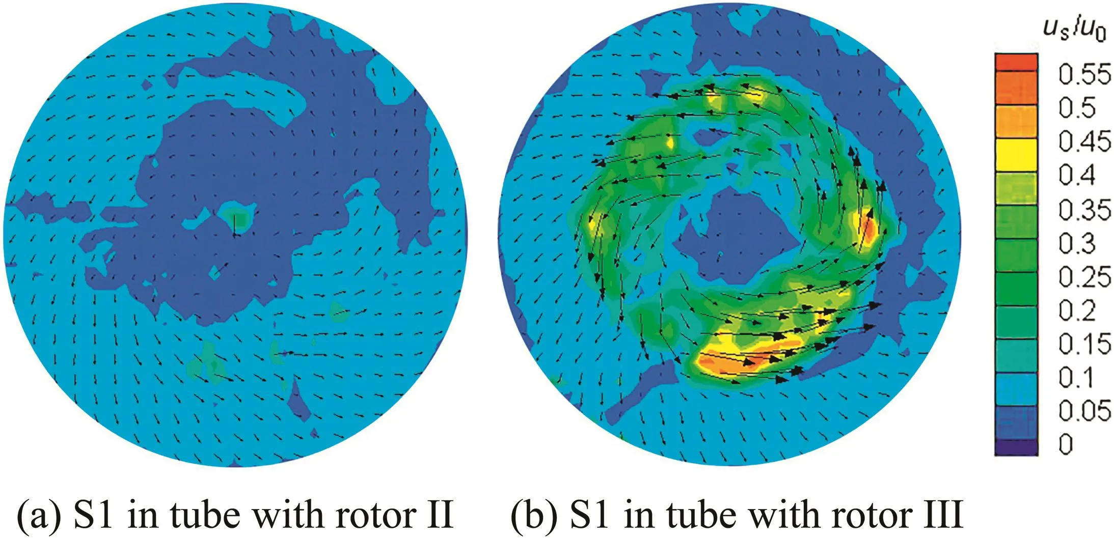
Fig.7.Velocity fields on transverse sections in the tubes with rotors II and III.

Fig.8.Turbulence intensity along different circumferences.
Fig.8 shows the turbulence intensity along different circumferences on section S1 in the tube with rotor I.Turbulence intensity represents the disturbance which rotors bring abouton fluid,and the disturbance is of greatimportance in enhancing the convective heattransfer of fluid in tube.Itcan be seen thatthe turbulence intensity along differentcircumferences would fluctuate,and it fluctuates in different extents at different R/R0:at R/R0=0.4 and R/R0=0.6,it fluctuates seriously;while at R/R0=0.2 and R/R0=0.8,it fluctuates gently.Because ofthe factthat R/R0=0.4 and R/R0=0.6 are in the rotational zones of the blades of rotor I,the results are caused by the ceaseless rotation of rotor I;as for R/R0=0.2 and R/R0=0.8,because they are near the central axis of rotor I and outside of the swing diameter of rotor I,the in fluence produced by the ceaseless rotation of rotor I is not strong,therefore the fluctuation is gentle.Nevertheless,the turbulence intensity fluctuates around certain value wherever R/R0is.
Since the turbulence intensity along differentcircumferences fluctuates around a certain value,it is necessary to analyze the average turbulence intensity along different circumferences.The average turbulence intensity along the radius R/R0on different sections in the tube with rotor I and plain tube is shown in Fig.9.It can be seen that the average turbulence intensities on sections S1 and S2 in the tube with rotor I are all higher than that on section in the plain tube,while they are different from each other.On section S1,the average turbulence intensity increases first and then decreases with the increase of the radius R/R0;the maximum value occurs at the margin of the blades of the rotor,and it is 253.6%higher than that of the plain tube.On section S2,the average turbulence intensity changes slightly within the swing diameter of the rotor,while it reduces outside of the swing diameter of the rotor,and the maximum value is 108.62%higher than that of the plain tube.These results demonstrate thatthe rotors enhance the disturbance of fluid primarily in the zone within the swing diameter of the blades,and itis higher on the section thatcontains the rotor than on the section that is behind the rotor.

Fig.9.Average turbulence intensity along the radius R/R0 on different sections.

Fig.10.Average turbulence intensity along the radius R/R0 in different tubes.
Fig.10 shows the average turbulence intensity along the radius R/R0on section S1 in the tubes with rotors I,II and III.It can be seen that the average turbulence intensity on section S1 in different tubes exhibits the same trend with the increase of the radius R/R0;the maximum value in the tube with rotor II is 53.5%lower than that in the tube with rotor I,and the maximum value in the tube with rotor III is 42.68%higherthan that in the tube with rotor I.The results are in accordance with the velocity fields in these three tubes,that is the rotor with three blades arouses more intense disturbance than the rotor with two blades does,and enlarging the lead of the rotor would reduce the disturbance.
3.3.The flow fields on longitudinal sections
Fig.11 shows the velocity fields on longitudinal sections in the tube with rotor Iand plain tube.Itcan be seen thatas with the velocity vector in the plain tube,there is no distinct deviation from the axis in the tube with rotor Ieither,which means thatthe radialvelocity is minor in comparison to the axial velocity in the tube with rotor I;in addition,compared with the velocity field in the plain tube,it is well-distributed in the tube with rotor I except for the region of the central axis because of the rotation of rotor I,and the even distribution of the flow field undoubtedly contributes to improve the convective heat transfer characteristics of fluid in the tube.To avoid the disadvantageous effect of the centralaxis on the projection of the laser source,the captured longitudinal section in the tube with rotor I had to be moved up beyond the central axis,and this has led to the results thatthe maximum value of u/u0in the tube with rotor I is lower than that in the plain tube.
Fig.12 shows the velocity fields on longitudinal sectionsin the tubes with rotors II and III.It can be seen that just like the velocity field in the tube with rotor I,it is well-distributed in the tubes with rotors II and III as well,and the velocity vectors in these two tubes are along the direction of the straight line too.
Radial velocity is the most direct quantity that promotes the exchange and mixing of mainstream fluid and fluid that is close to the tube wall,so in the following the radial velocity is extracted to further analyze and compare the differences between the tubes with rotors I,II,and III and the plain tube.
Fig.13 shows the radial velocity along x(the direction of fluid flow)atdifferent R/R0in the tube with rotor I.Itcan be seen thatthe radialvelocity fluctuates constantly with the increase of x,but as a whole it presents the following trend:itis high in the region ofthe existence ofrotor I,then it decreases and ultimately maintains at a steady level.The reason why it fluctuates is also that the rotor is ceaselessly rotating.It can also be seen that the ur/u0is higher at R/R0=0.25 than at R/R0=0.5;as for the ur/u0at R/R0=0.75,because it is outside of the swing diameter,it is mainly caused by the turbulent fluctuation,and the in fluence of rotor I is tiny.At R/R0=0.25,the direction of ur/u0in the region behind rotor I is contrary to that in the region of the existence of rotor I,and this is in accord with the fact that the direction of the swirling flow is reversed,which occurred on section S2.

Fig.11.Velocity fields on longitudinal sections in the tube with rotor I and plain tube.

Fig.12.Velocity fields on longitudinal sections in the tubes with rotors II and III.

Fig.13.The radial velocity along x.

Fig.14.The radial velocity along x in different tubes.

Fig.15.The radial velocity along the diameter D/D0 in different tubes.
The radial velocity along x at R/R0=0.5 in the tubes with rotors I,II,and III and plain tube is shown in Fig.14.It can be seen that the radial velocity ur/u0in the region of the existence of rotors in the tubes with rotors I,II and III all increases by a large amount compared with that in the plain tube,which means that it makes great contribution to the augmentation of the radial velocity by inserting the rotors into the tube.As for the amplitude of increase,it is approximate in the tubes with rotors I and III,and it is least in the tube with rotor II.The results mean that the radial velocity of the rotor with three blades is approximate to that of the rotor with two blades,and enlarging the lead of the rotor would reduce the radial velocity.
Fig.15 shows the radialvelocity along the diameter D/D0at x=40 mm in the tubes with rotors I,II,and III and plain tube.It can be seen that the radial velocity is high in the tubes with rotors I,II and III,particularly in the zone of the swing diameter of the rotors,while it is merely the turbulent fluctuation in the plain tube.Likewise,the magnitude of the radial velocity is in accord with the results obtained in Fig.14:it is approximate in the tubes with rotors I and III,and it is least in the tube with rotor II.With regard to the distribution of the radial velocity,it has no definite trend with the increase of D/D0,but anyway the effect of promoting the exchange and mixing of the fluid in the tube,which the rotor has brought,is remarkable.
4.Conclusions
In this work,the PIV experiments regarding the flow fields in the tube inserted with different rotors and the plain tube were conducted and the flow characteristics on the transverse section and longitudinal section were analyzed.The conclusions could be drawn as follows:
Swirling flow was produced in the tube inserted with rotors:it was particularly strong within the swing diameter ofthe rotor on the section that contains the rotor,and the direction of the swirling flow within the swing diameter of the rotor on the section behind the rotor was contrary to thatin otherregion ofthe tube;the average turbulence intensity and the radial velocity were improved notably;the velocity vectors on the longitudinal section remained along the direction of a straight line;both the swirling flow and average turbulence intensity were higher for the rotor with three blades than for the rotor with two blades except that the radial velocity was about the same,but they were all reduced by enlarging the lead of the rotor.Characterization of the flow patterns in a circular tube contributes to understanding the heat transfer efficiency and scale inhibition performance of the rotor-assembled strand and provides guidance for its application.
杂志排行

Chinese Journal of Chemical Engineering的其它文章
- PIVexperimentand large eddy simulation ofturbulence characteristics in a confined impinging jet reactor☆
- CFD predictions for hazardous area classification
- Hydrate agglomeration modeling and pipeline hydrate slurry flow behavior simulation☆
- Improving the performance of a thermoelectric power system using a flat-plate heat pipe☆
- Extending the EMMS/bubbling model to fluidization of binary particle mixture:Formulation and steady-state validation☆
- Numerical simulation of flow focusing pattern and morphological changes in two-phase flow inside nozzle☆