A Bio-Inspired Global Finite Time Tracking Control of Four-Rotor Test Bench System
2018-12-26RoohulAminIrumInayatLiAijunShahaboddinShamshirbandandTimonRabczuk
Rooh ul Amin,Irum Inayat,Li Aijun,Shahaboddin Shamshirband and Timon Rabczuk
1 School of Automation,Northwestern Polytechnical University,Xi’an,710072,China.
2 Department of Computer Science,National University of Computer and Emerging Sciences,Islamabad,44000,Pakistan.
3 Department for Management of Science and Technology Development,Ton Duc Thang University,Ho Chi Minh City,Vietnam.
4 Faculty of Information Technology,Ton Duc Thang University,Ho Chi Minh City,Vietnam.
5 Institute of Structural Mechanics,Bauhaus University Weimar,99423,Weimar,Germany.
Abstract:A bio-inspired global finite time control using global fast-terminal sliding mode controller and radial basis function network is presented in this article,to address the attitude tracking control problem of the three degree-of-freedom four-rotor hover system.The proposed controller provides convergence of system states in a predetermined finite time and estimates the unmodeled dynamics of the four-rotor system.Dynamic model of the four-rotor system is derived with Newton’s force equations.The unknown dynamics of four-rotor systems are estimated using Radial basis function.The bio-inspired global fast terminal sliding mode controller is proposed to provide chattering free finite time error convergence and to provide optimal tracking of the attitude angles while being subjected to unknown dynamics.The global stability proof of the designed controller is provided on the basis of Lyapunov stability theorem.The proposed controller is validated by(i)conducting an experiment through implementing it on the laboratory-based hover system,and(ii)through simulations.Performance of the proposed control scheme is also compared with classical and intelligent controllers.The performance comparison exhibits that the designed controller has quick transient response and improved chattering free steady state performance.The proposed bioinspired global fast terminal sliding mode controller offers improved estimation and better tracking performance than the traditional controllers.In addition,the proposed controller is computationally cost effective and can be implanted on multirotor unmanned air vehicles with limited computational processing capabilities.
Keywords:Bio-inspired global fast terminal sliding mode controller,attitude tracking,radial basis function network,four-rotor hover system.
1 Introduction
A noticeable surge has been witnessed in use of Multirotor UAV(MUAV)for numerous civil and strategic defense applications including aerial shooting,transportation,urban surveillance,and rescue operations,in the recent past.It is because of several outstanding properties of MUAV(s)such as its low development cost,structural simplicity,hovering capability,and low speed maneuverability [Raptis and Valavanis(2011)].Literature shows several configurations of MUAV(s)i.e.four-rotor,quadcopter,hexarotor,and octorotor for which various controllers have been designed to tackle variable operating conditions(e.g.[Bouabdallah,Noth,Siegwan et al.(2004); Hoffmann,Huang,Waslander et al.(2007); Pounds,Mahony and Corke(2010); Rinaldi,Chiesa and Quagliotti(2012);Chen and Huzmezan(2003); Amin and Aijun(2017)]).Conventional linear controllers(e.g.PID,Linear Quadratic,and robust H∞ controllers)implemented to control MUAV(s)(e.g.[Bouabdallah,Noth,Siegwan et al.(2004); Hoffmann,Huang,Waslander et al.(2007); Pounds,Mahony and Corke(2010); Rinaldi,Chiesa and Quagliotti(2012); Chen and Huzmezan(2003); Amin and Aijun(2017); Amin and Aijun(2016)])are designed on the mathematical model linearized about the fixed heave state.These classical linear control methods were not found practically viable for controlling trajectory tracking of MUAV,especially in presence of parametric uncertainties and modeling inaccuracies.Hence,it can be concluded that apart of the availability of several controllers for MUAV[Amin,Aijun and Shamshirband(2016)],the effective control of MUAV(s)is still active control problem due to its complex nature and highly coupled system dynamics.
Literature study reveals that nonlinear control techniques have outperformed classical control methods in dealing with parametric and un-parametric uncertainties and outward disturbances.Among others,Sliding Mode Controller(SMC)has been proved as the most efficient and effective robust technique in handling uncertain systems [Lantos and Márton(2011)].Moreover,literature review also states several SMC based techniques developed for 3 DOF four-rotor system and quadcopter such as use of SMC for quadcopter control was introduced by Bouabdallah and Siegwart [Bouabdallah and Siegwart(2005)].The results of the aforementioned technique exhibited poor performance and chattering in output states [Bouabdallah and Siegwart(2005)].Xu et al.also employed SMC for quadcopter but the major limitation was that simulations were not performed on a real platform [Xu and Ozguner(2006)].Exact feedback linearization was proposed for quadrotor control by Mian et al.[Mian and Wang(2008)],and Voos[Voos(2009)].On comparison between feedback linearization controller and SMC,the latter showed efficient performance in noisy conditions [Lee,Κim and Sastry(2009)].Bouadi proposed SMC based adaptive tracking controller for quadcopter with model uncertainties and in presence of external turbulences [Bouadi,Simoes Cunha,Drouin et al.(2011)].Yang et al.presented Adaptive Fuzzy SMC(AFSMC)for attitude and position tracking of quadcopter subjected to actuator failure [Yang,Jiang and Zhang(2014)].Recently,Sumantri et al.[Sumantri,Uchiyama and Sano(2016)] proposed a least-square based SMC for chattering free quadrotor control.However,sliding surface was usually a linear subspace of the system states in the aforementioned sliding mode based controllers.This results in the convergence of errors to origin in infinite time that only ensures asymptotic stability.
Terminal SMC(TSMC)and fast terminal SMC(FTSMC)are the two variants of SMC designed to achieve stability in finite time.Venkataraman & Gulati introduced TSMC for nonlinear systems [Venkataraman and Gulati(1992)] which was then successfully employed for uncertain linear and MIMO systems(e.g.[Man and Yu(1997); Wu,Yu,and Man(1998)]).However,TSMC proved inefficient in finite time convergence in such operational conditions where system states are far-off from the origin.Moreover,TSMC suffers from singularity problem in robotic manipulators control.The singularity problem was addressed by Feng et al.by introducing nonsingular TSMC(NTSMC)for control of rigid manipulators [Feng,Yu and Man(2002)].The first issue was resolved by Yu &Man,by introducing FTSMC for nonlinear dynamic systems for convergence of system states,whether being close or away in fast finite time [Yu and Man(2002)].However,FTSMC also has singularity problem [Feng,Yu and Man(2002)] which was addressed by Yu et al.[Yu,Du,Yu et al.(2008)],by introducing a nonsingular FTSMC(NFTSMC);a recursive FTSMC for finite time convergence of nth-order system to resolve singularity problem.Nonetheless,FTSMC and NFTSMC both lack adaptability and learning properties and face chattering problem [Li,Dou and Su(2011)].Therefore,it can be observed that system stability can be compromised with poor system performance.However,augmentation of an adaptive or learning based controller with FTSMC and NFTSMC and a bio-inspired switching law can serve purpose.
With the advent of intelligent controllers,fuzzy logic and neural network-based controllers are gradually being employed in many applications and systems with uncertain system dynamics(e.g.[Yu,Li and Li(2011); Fu,Wu,Κo et al.(2011); Lian(2014); Κaiser,Chowdhury,Mamun et al.(2016); Sun and Li(2015); Chohra,Benmehrez and Farah(1998)]).In particular,Radial Basis Function Network(RBFN)controllers have been used in several mechanical and electro-mechanical systems(e.g.[Liu(2012); Feng,Xiao,Leung et al.(2014)]).An RBFN approximates the dynamical model and provides a unique solution for a specific data set.In addition,RBFN also provides noise tolerance,enhanced system stability,and quick learning as compared with other learning-based controllers [Yu and Xie(2011)].Literature shows that a considerable number of studies have been conducted to cater parametric uncertainties,external disturbances,and actuator failure for different configurations of MUAV.However,attitude tracking problem with unmodeled dynamics approximation still needs attention,which can cause the MUAV instability during operation making it prone to intermittent issues.Recently,Amin et al.[Amin,Aijun,Κhan et al.(2016)] proposed tracking controller using adaptive extended normalized radial basis function(AENRBF)to address the tracking problem with unmodeled dynamics estimation.The proposed controller was successfully tested on a four-rotor test bench system subjected to outward disturbances.However,the controller did not provide any means to control convergence time and high computation was required for the computation of ENRBF.This shows that the proposed controller is not feasible for micro MUAV aimed to operate in disturbance free environment with limited processing power.This provides the motivation to explore more on intelligent controllers for MUAV control.
In this study,a Bio-Inspired Global Fast-Terminal SMC(BIGFTSMC)in conjunction with RBFN is proposed for attitude tracking control of four-rotor test bench system.The RBFN is employed to estimate the neglected system dynamics and to overcome the aforementioned FTSMC issues.BIGFTSMC provides fast and finite time tracking of attitude angles irrespective of system states’position from the equilibrium point.The Bio-inspired switching law is employed to eradicate chattering phenomena.The closedloop system stability is analyzed using Lyapunov stability theorem and it is showed that the designed controller provides stable tracking performance.The efficiency of the designed controller is examined using numerical simulation and simulation results are also compared with classical PID controller and AENRBFN controller.Moreover,the proposed BIGFTSMC is tested on four-rotor test bench system to validate effectiveness through experiment.The contributions of this study are stated as:
1.BIGFTSMC in conjunction with RBFN is used for tracking control problem of MUAV which is computationally cost effective as compared with the previous work such as AENRBFN(e.g.[Amin and Aijun(2017); Amin,Aijun,Κhan et al.(2016)]).
2.Fast finite time convergence of states is provided irrespective of the initial conditions,that is an exceptional feature of the designed controller unavailable in the previous work(AENRBFN)and classical controller i.e.PID(e.g.[Amin and Aijun(2017);Amin,Aijun,Κhan et al.(2016)]).
3.Bio-inspired switching law is introduced with FTSMC for chattering free response,which is not a characteristic of AENRBFN and PID controllers.
4.The stability of the complete system with designed BIGFTSMC is investigated and proof of asymptotic stability of the closed loop system is also provided.
The rest of the article is structured as follows.In Section 2,the four-rotor test bench experimental setup,dynamic model and problem statement are presented.In Section 3,the RBFN based dynamic estimation,BIGFTSMC design,and closed-loop system stability analysis is provided.Numerical simulation and experimental findings are given in Section 4.In the end,Section 5 concludes this article.
2 Experimental setup
2.1 Structure details
The four-rotor system is a 3-DOF laboratory test bench system developed by Googol Systems [Googol Technology(2012)].The four-rotor hover system is used to design and implement flight control laws for MUAV(s).The flight controllers designed for the fourrotor test bench can also use for attitude tracking control of other variants of aerial vehicles.The four-rotor experimental system is shown in Fig.1.
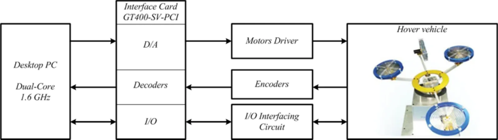
Figure 1:Four-rotor test bench experimental system
The test bench system comprises of a moving platform and a control cabinet.The moving sub-system comprises of four propellers connected to a circular gimbal called front,back,left,and right propellers.The gimbal is fixed on a universal joint that restricts the linear motion(i.e.surge,sway,and heave)of the hover system and only allows the 3DOF rotational motion(i.e.pitch,roll,and yaw).The 3DOF rotational motion is caused by the torque(s)generated by propellers.For instance,the pitch motion is caused by front,right,and left propellers; the roll motion is caused by right and left propellers; and the yaw motion is caused by the back propeller.High precision encoders are attached with the propellers’motors that determine the angles of rotational motion.The hover system moving platform is connected to a computer system through a control cabinet.The computer system provides the users with the facility to design and test flight controllers using MATLAB/Simulink.The computer system is connected to the control cabinet through a PCI card(GT400-SV-PCI).The PCI card comprises of D/A converters(DACs),decoders,digital,and analog inputs/outputs(I/Os).
2.2 Dynamical model
Four-rotor hover system has four inputs and three outputs.The thrust forces produced by the propellers denoted as Flfor left propeller,Frfor right propeller,Fffor front propeller,and Fbfor back propeller are the inputs.The system outputs are denoted aswhere φrepresents roll angle,θis pitch angle and ψis yaw angle.Front,right,and left propellers are at equal distance equidistant lffrom center as presented in Fig.2 [Amin,Aijun,Κhan et al.(2016)].
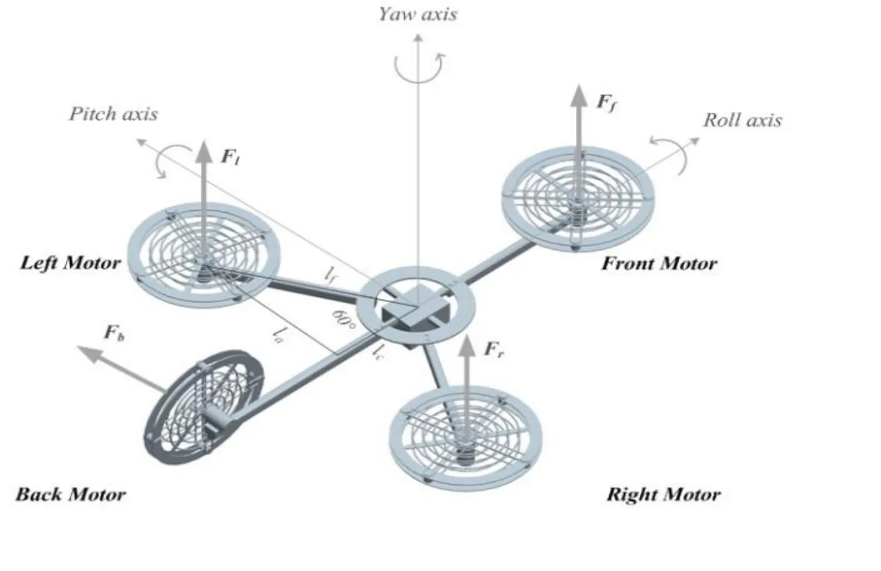
Figure 2:Four-rotor test bench system structure
The assumptions made while modeling four-rotor test bench system are stated below:
· The four-rotor system has a symmetrical and rigid structure.
· The inertia matrix of the four-rotor system is time invariant.
· Roll and pitch angle movements are limited to ±15° due to structural constraints.
The roll motion is determined using the following equation
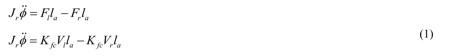
Where Jris the roll axis inertial moment and Kfcis a constant that represents voltage to thrust ratio.Fig.2 shows thatTherefore the Eq.(1)is rewritten as

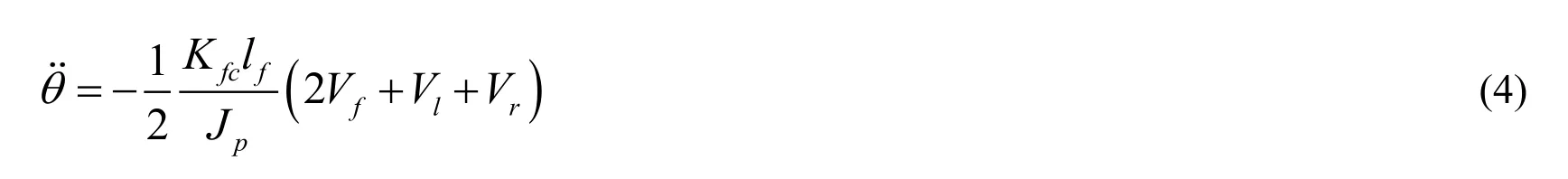
Likewise,the pitch movement is determined by the following equation
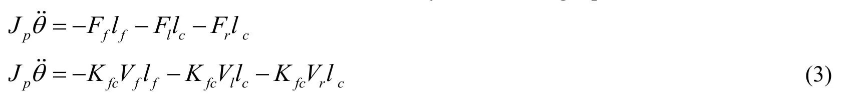
Where Jpis the pitch axis inertial moment.Fig.2 shows that
Therefore the Eq.(3)can be rewritten as
The yaw movement is determined by the following equation
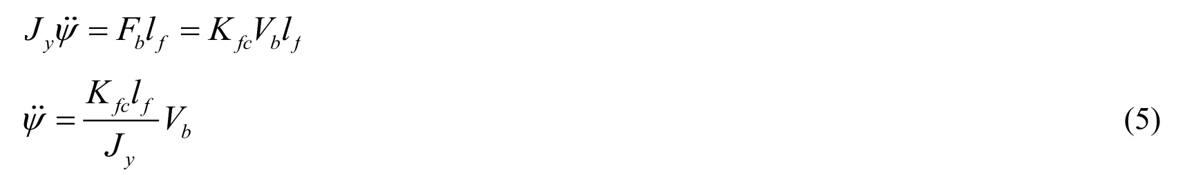
Where Jyis the yaw axis inertial moment.
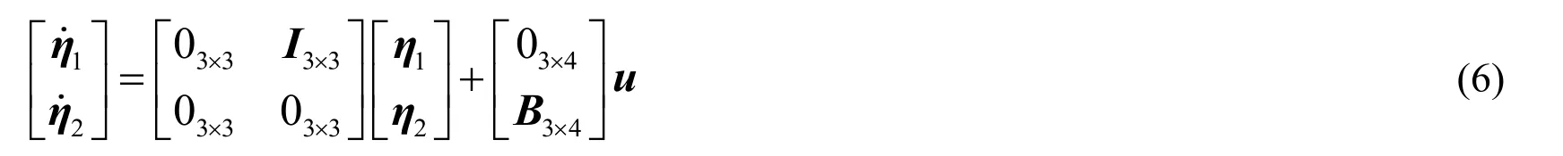
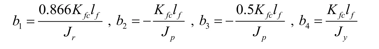
Let system states defined asand control input definedUsing the above defined vectors,Eqs.(2),(4),and(5)can be rewritten as
2.3 Problem formulation
The complete dynamical model of four-rotor system is defined as follows


This study is aimed to estimate the neglected dynamics and to propose a controller for the four-rotor hover system such that output vector ηtrack the reference vectorηdwithin finite time and without any steady-state error.The assumptions made in the control design of four-rotor system are given as following:
Assumption 1:The reference state vector ηdand its time derivatives are bounded and continuous.
Assumption 2: The nonlinear functionis bounded and differentiable.
3 Controller design
3.1 RBFN based dynamics estimation
In this research,the unmodeled dynamics of four-rotor test bench system are estimated using RBFN.The RBFN has feed forward network structure with four layers:(i)An input layer having n inputs,(ii)A hidden layer having l neurons,(iii)A normalized layer having l nodes,and(iv)An output layer,as shown in Fig.3.
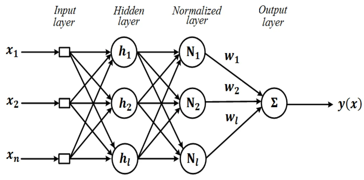
Figure 3:The RBFN architecture
Input Layer:The input layer takes an input vectorand passes on the input vector to the hidden layer.The input vector is comprised of error and error derivatives of all output states i.e.roll,pitch,and yaw.The error values are real numbers and error ranges are same for roll and pitch but are different for yaw.Hence,input vector is not normalized between [0,1].
Hidden Layer:The hidden layer comprises of l neurons and each neuron node in the hidden layer receives an input vectorx .Each node is comprised of a Gaussian function that changes the input to a nonlinear function,described as

Where cjrepresents origin vector,represents Euclidean distance,and σis the distance between input and origin of the Gaussian function.The hidden layer transmits the data to the normalized layer.
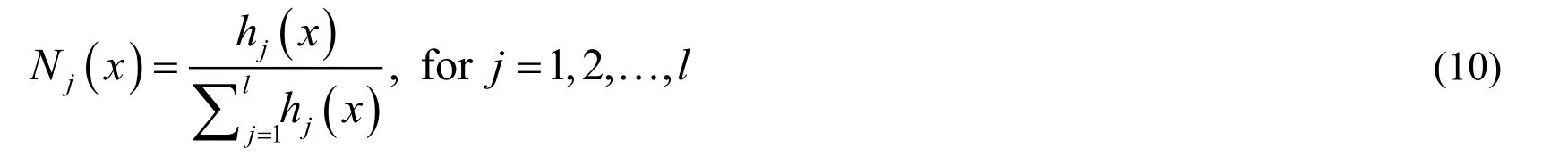
Normalized Layer:In this layer,Gaussian functions are normalized to enhance the consistency of the input data range.The output of this layer is shown as
Output Layer:The output layer is an algebraic summation of weighted normalized outputs,which is shown as

The optimization of the weight vector w is performed using Levenberg-Marquardt(LM)algorithm as a learning method.The cost function of RBFN is defined as
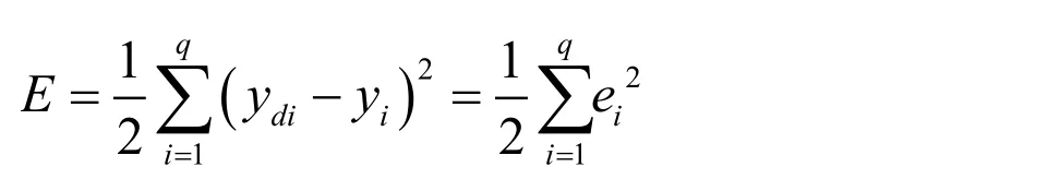
Whereydiand yirepresents the expected response and actual response of the particular system output respectively.In LM algorithm,the weight update Δ wiis determined to minimize the following expression.
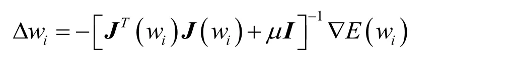
Where wiis the weight vector,e(wi)is the error vector,J(wi)is the Jacobian matrix of e(wi),and μis the learning parameter.The LM algorithm continues to update weight matrix till the cost function is optimized.If the cost function is optimized at step n,the weight update of RBFN is given as

The steps used in RBFN training using LMA are given in algorithm 1.
Definition 1 [Beirami(2006)]:Any continuous,bounded,and differentiable function can be defined as:

Remark 1:The size of a RBFN is characterized by the number of neurons in the hidden layer.In control applications,selection of hidden layer neurons is the most critical task.If number of neurons is limited,it may not fully solve the problem.On the contrary,a complex network is always inclined to memorize unnecessary data.This result in the form of noise added in the learning stage.
The selection of hidden layer neurons in control application is still a challenging task as no analytical solution has been devised till date.The typical heuristic approach is used for selection,in which various networks are trained with increasing complexity and estimation errors of all networks are observed.After training,all the network models are compared and,the network with the lowest error is selected.
Remark 2:According to Definition 1,any unknown bounded function can be estimated using RBFN with desired accuracy.The Eq.(13)can also be written as

3.The derivative of matrix w is very small and
The RBFN output in Eq.(11)is rewritten as

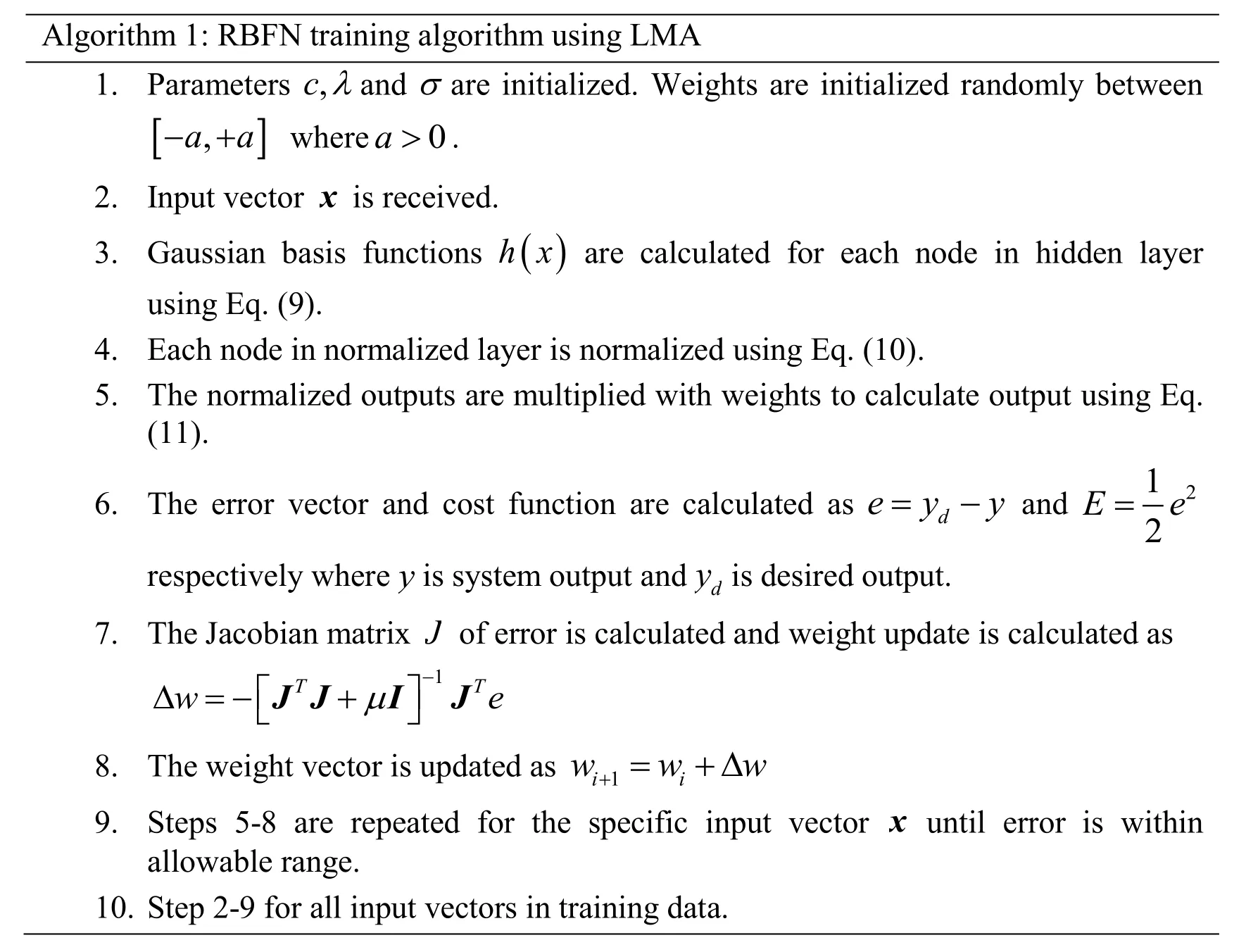
Algorithm 1:RBFN training algorithm using LMA 1.Parameters and are initialized.Weights are initialized randomly betweenwhere.2.Input vector is received.3.Gaussian basis functions are calculated for each node in hidden layer using Eq.(9).4.Each node in normalized layer is normalized using Eq.(10).5.The normalized outputs are multiplied with weights to calculate output using Eq.(11).6.The error vector and cost function are calculated as andrespectively where is system output and is desired output.7.The Jacobian matrix of error is calculated and weight update is calculated as 8.The weight vector is updated as 9.Steps 5-8 are repeated for the specific input vector until error is within allowable range.10.Step 2-9 for all input vectors in training data.
3.2 Bio-inspired global fast terminal sliding mode control(BIGFTSMC)design
The dynamical model of four-rotor system presented in Eq.(7)(Section 2.3)can also defined as


The global fast terminal sliding vector is proposed as

The time derivative of Eq.(18)results in
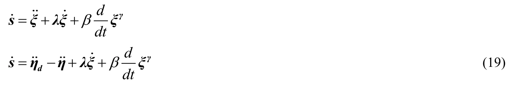
Substitution of Eq.(17)in Eq.(19)gives

Theorem 1:The tracking error ξof attitude angles of the four-rotor system will exponentially converge to origin in finite time if there exists a control law defined as

Where B-†represents the pseudo inverse of matrix B,φ,α>0,and δsis the bioinspired switching law.
Proof:First we provide the proof of tracking error convergence to the zero with the defined sliding surface and then the proof of finite time conversion is provided.Substitution of the proposed control law(Eq.(21))in Eq.(20)results in

Multiplying s with the Eq.(22)results in

Sinceγ,αand φare positive numbers and δsis a switching law,this implies
The sliding surface defined in Eq.(18)at s=0can be written as

When the tracking errorξis far-off from the origin,the convergent time is dominated by the fast terminal termβξγ.When the error approaches the sliding surface the convergent time is determined usingEq.(24)can be written as
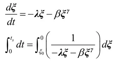
Thus,the time interval in which tracking error converges to zero is given as

Therefore,it is showed that by appropriate values of λ,β,and γ,the tracking error is converged to origin in finite predefined time ts.
io-Inspired Switching Law:
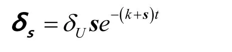
The bio-inspired switching law was introduced by Yang et al.[Yang,Zhu,Yuan et al.(2012)].In this work a modified bio-inspired switching law δsis combined with FTSMC for chattering free finite time convergence of system states.The switching law rate is defined as

Where δsis the bio-inspired switching law,k is the decay constant,δUand δLare upper and lower bounds of the switching law(δU,δL>0),and δ+and δ-are positive and negative switching functions such that
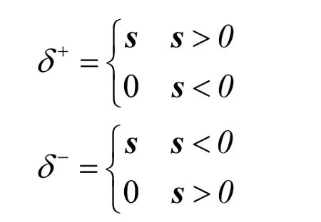
For positive sliding surface0>s ,the negative switching function becomes zero and solution of Eq.(26)results in the following switching law:
Sincek+s>0,it is clear from the above equation that as s →0,δs→0.
Similarly,for negative sliding surface,s<0,the positive switching function becomes zero and solution of Eq.(26)results in the following switching law:

Since k-s >0,it is clear from the above equation that as s →0,δs→0.
Hence,it shows that the bio-inspired switching law for different sliding surfaces results in smooth switching without any chattering.
3.3 Stability analysis
The definitions used in the stability analysis are stated here [Slotine and Li(1991)].
Definition 2:If a positive definite Lyapunov candidate function V(x)exists for a dynamical system so that V(0)=0and(x)<0,then the dynamical system is said to be asymptotically stable.
Definition 3:If asymptotic stability holds for any of the initial states,the system is said to be globally asymptotically stable.
Theorem 2:If the proposed controller(Eq.(21))in conjunction with RBFN based estimated dynamicsis used for four-rotor system control,then global asymptotic stability of the closed-loop system is guaranteed.

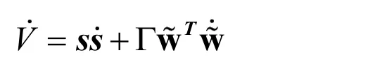
Proof:Let the Lyapunov function is defined as The time derivative of the defined Lyapunov function results as

The weight update is taken as

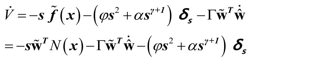
Now the Eq.(28)becomes

Sinceγ,αand φare positive numbers,this implies φ s2+αsγ+1≥0so the Eq.(30)becomes V <0.Since the Lyapunov function is steadily decreased,therefore closed loop system is globally stable.Thus,the designed system is globally asymptotically stable.
4 Results and discussions
In this section simulation and experimental findings are shown to demonstrate the efficiency of the designed controller.The simulations and experiment are performed to validate the proposed controller and to implement the controller on the laboratory-based hover system.First of all,unit step output of BIGFTSMC is determined and compared with outputs of classical PID and AENRBFN controllers.Next,tracking response of BIGFTSMC is studied with sinusoidal input trajectory.The four-rotor test bench system parameters are listed in Tab.1.
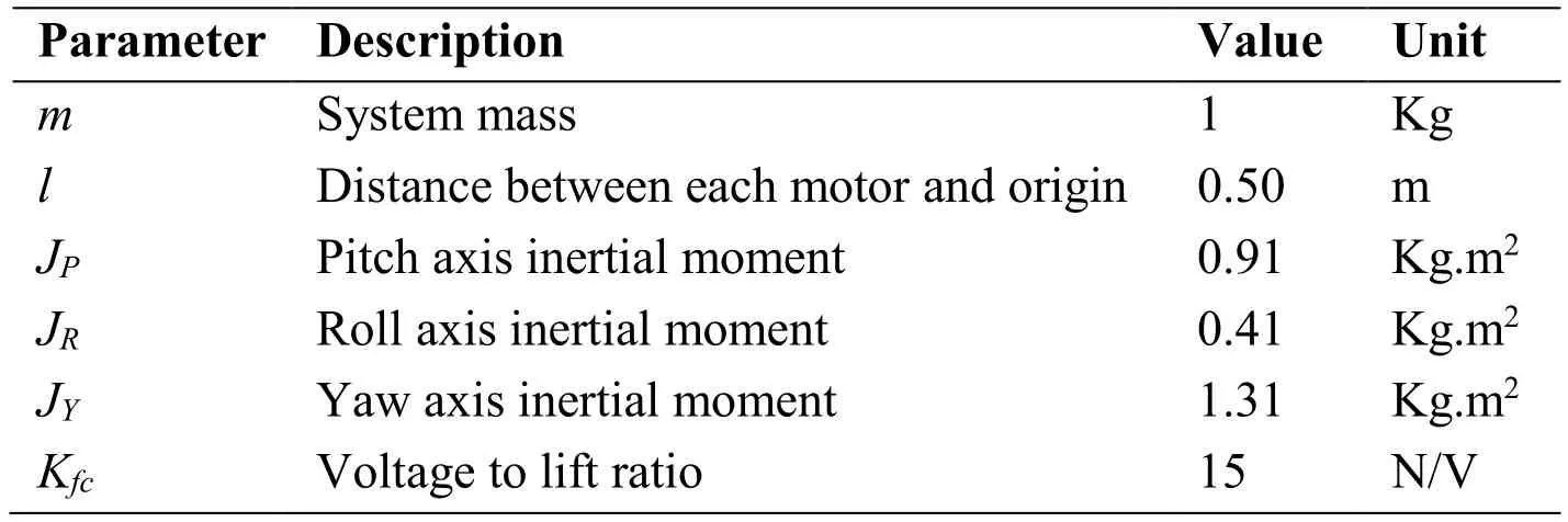
Table 1:Four-rotor hover system parameters
4.1 RBFN supervised training
The RBFN is trained to estimate the four-rotor system unknown dynamics.The proposed RBFN has three substructures with respect to system outputs.Each substructure is comprised of two input nodes,five hidden nodes,five normalized nodes,and an output node.The input vector is comprised of error and error derivatives for all output states i.e.roll,pitch,and yaw,expressed asThe initial weights of the hidden neurons are randomly generated within the interval [-1,1].The training data covers the learning space {-1 5,-1 0,-5,0,5,10,15}considering the maneuverability of the hover system.The number of learning episodes is set to 10000 with learning rateμ=0.1.Each learning episode will stop if the hover system tracks the desired reference input and error is within allowable rangeε=0.05.The heuristic approach is considered for selection of number of learning episodes i.e.RBFN is trained with various learning episodes and it is found that optimal solution can be obtained with around 10000 learning episodes.
The error convergence for the RBFN training is shown in Fig.4.
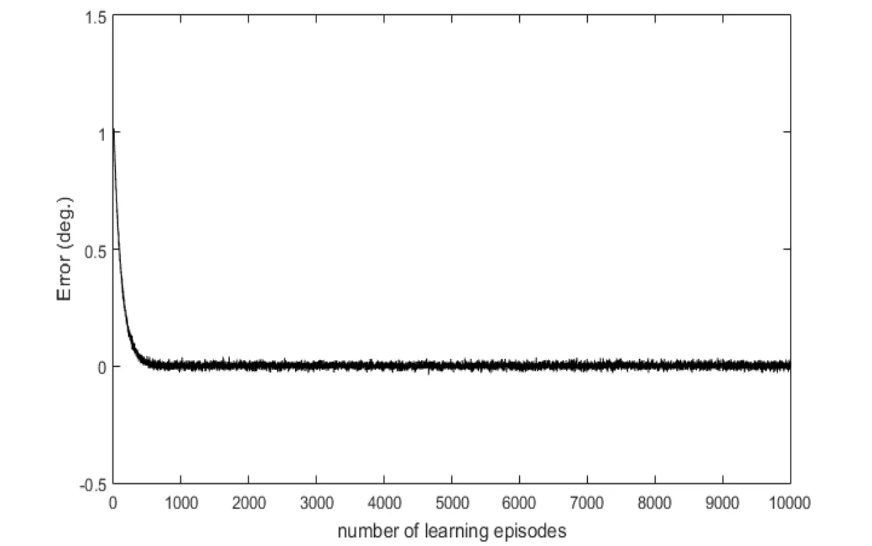
Figure 4:Error convergence in RBFN training
4.2 Simulation results
Simulation results are presented in this sub-section.Initially,step output of BIGFTSMC is determined and compared with step outputs of PID and AENRBFN controllers.In the second case,the response of four-rotor system with sinusoidal reference trajectory is presented.For simulation,frictional moment is supposed as unknown dynamics to investigate the performance of proposed RBFN.Therefore,unknown dynamics is considered as

where Κ represents friction constant matrix i.e.After few trials,selected controller parameters areandwhere Λ=0.50and ε=0.10.Firstly,step input of 2° is used as a reference input for both tilt angles.The tracking response of the proposed BIGFTSMC,as well as PID and AENRBFN controller responses are shown in Fig.5.The responses clearly show that the proposed BIGFTSMC controller has an improved transient response and system’s outputs follow the given reference input faster than PID and AENRBFN controllers.In addition,BIGFTSMC’s response is free form chattering or oscillations which are normally present in SMC based controllers.PID controller offers slightly fast settling time as compared to AENRFBN but the response has unwanted overshoots with constant steady state error.Error plots are presented in Fig.6.Error plots clearly show that error states converge to equilibrium faster than AENRBFN controller,which offers better error response as compared with LQR and AFSMC [Amin,Aijun,Κhan et al.(2016)].Hence,it indicates that BIGFTSMC is capable of steady and improved tracking as compared with conventional and AENRBFN controllers.The performance comparison is summarized in Tab.2.
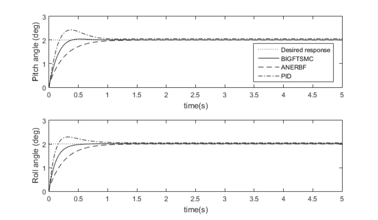
Figure 5:Step responses of PID,ANERBF and BIGFTSMC controllers
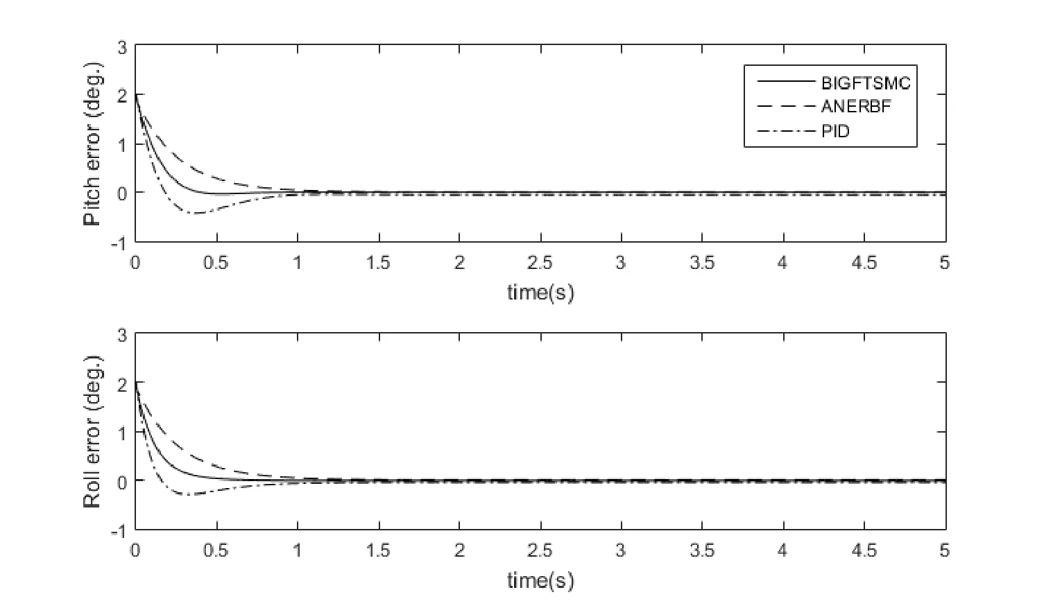
Figure 6:Error responses of PID,ANERBF and BIGFTSMC controllers
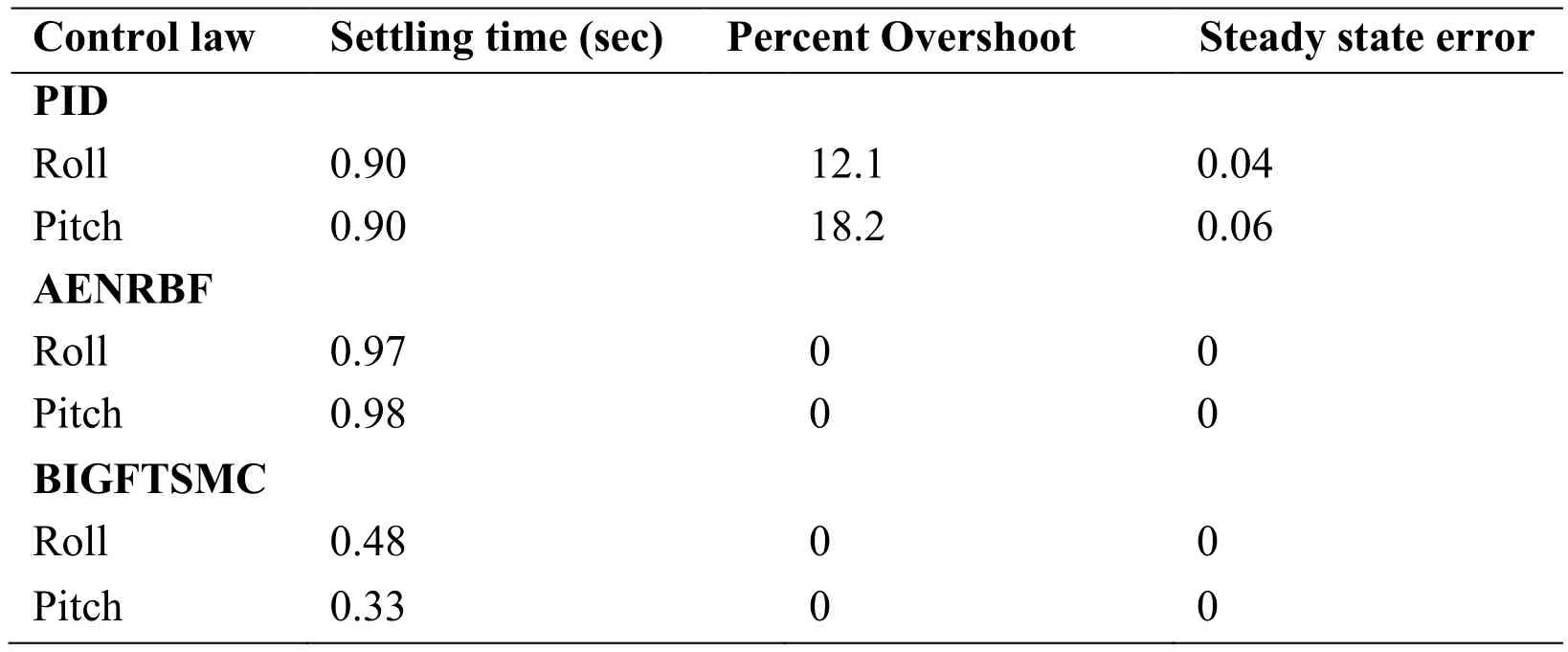
Table 2:Comparison of PID,AENRBFN and BIGFTSMC controllers
In the second case,sine wave of 3° is used as the reference inputs for roll,pitch and yaw angles to evaluate controller efficiency.The tracking outputs of this case are presented in Fig.7.The outputs show that the designed BIGFTSMC follows the input trajectory in real-time without any observable error.Error plots are presented in Fig.8.The plots clearly show that within no time errors are converged to less than 0.01% amplitude of the input signal and remain in that limit.This limit is quite suitable for practical applications as it is due to electromechanical nature of the system.The unknown dynamics approximation errors are presented in Fig.9.The approximation errors are within acceptable range which is obvious from Fig.9.In a nutshell,simulations clearly exhibit that BIGFTSMC provides an improved and better tracking response.Moreover,RBFN very quickly estimates the unknown dynamics and prevents the system to become unstable due to modeling inaccuracies.
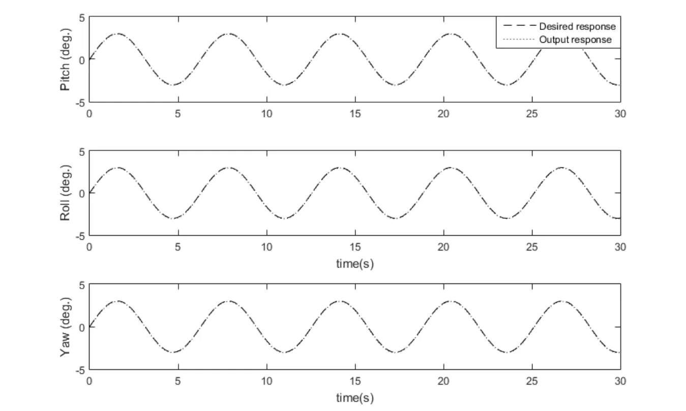
Figure 7:BIGFTSMC output response to sine inputs
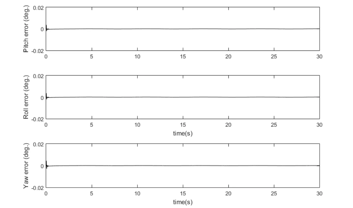
Figure 8:BIGFTSMC error response
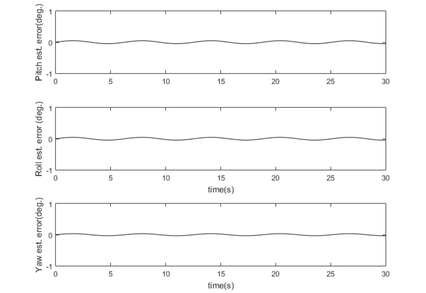
Figure 9:Unknown dynamics estimation errors
4.3 Experimental results
After achieving satisfactory simulations,the proposed control law is applied to a fourrotor hover test bench system for controller validation.The four-rotor test bench system is presented in Section 2.The computer with the test bench is available with Simulink based software interface for implementation of designed control laws.The software interface is available with LQR controller as shown in Fig.10.The LQR block is replaced by the proposed controller defined in Eq.(21).The RBFN parameters used in simulations are also used in the experiment.The sine waves of amplitude 3° with 180°phase shift are used as reference inputs for roll and pitch angles.The tracking outputs are presented in Fig.11.The outputs clearly show that roll and pitch outputs track the reference signals without any error and chattering.The error plots are presented in Fig.12.The errors magnitudes are slightly higher than that the ones obtained in simulation but are still in the acceptable error limit for real-time tracking.Unknown dynamics estimation plots are presented in Fig.13.The plots clearly show that estimation response is consistent with the reference input.Thus,RBFN has proved very effective in real time unknown dynamics approximation.It is concluded form experimental results that the designed BIGFTSMC provides improved tracking performance.Moreover,controller performance in experimental results validates the numerical simulations.
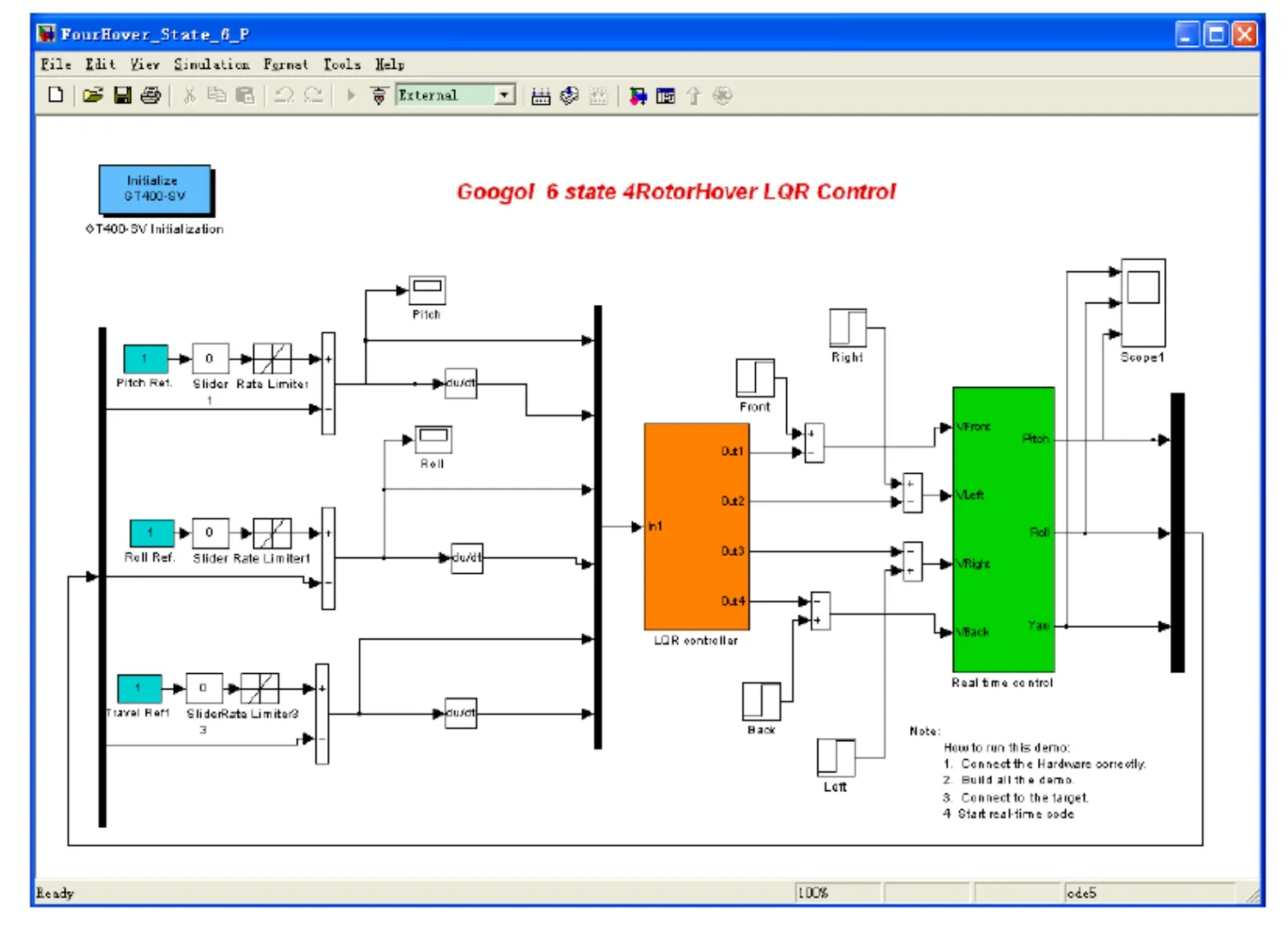
Figure 10:Four-rotor hover system controller relaization
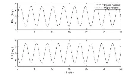
Figure 11:Four-rotor test bench system output response
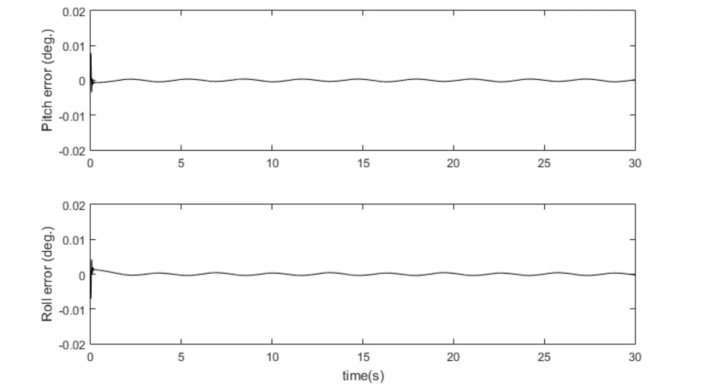
Figure 12:Four-rotor test bench system error response
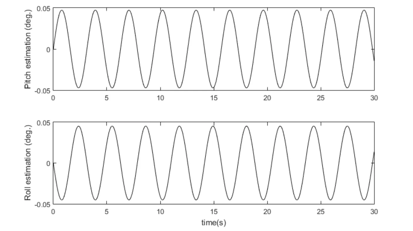
Figure 13:Four-rotor test bench system dynamics estimation response
5 Conclusion
In this work,RBFN based BIGFTSMC is presented to address tracking control problem of four-rotor test bench system.Dynamic model of the four-rotor system is derived with Newton’s force equations.The unknown dynamics of four-rotor systems are estimated using RBFN and LMA is used as learning algorithm to train RBFN.The BIGFTSMC is designed using bio-inspired switching law to ensure fast convergence of errors and to provide improved chattering free tracking response even with modeling inaccuracies.The global stability proof of BIGFTSMC is provided using Lyapunov stability theorem.The comparison with PID and adaptive ENRFBN controller verifies that the proposed controller achieves improved and fast transient response and chattering free steady state response.In addition,the proposed BIGFTSMC controller is computationally cost effective and can be implanted even on micro MUAV with limited computation processing capabilities.Simulation and experimental results show acceptable estimation and tracking performance which demonstrate the effectiveness of the designed controller.This work can be combined with fault tolerant control(FTC)method to address actuator failure problem.Furthermore,disturbance observer can be designed and included to mitigate the external disturbance effect for operation in extreme weather conditions.
杂志排行

Computers Materials&Continua的其它文章
- Natural Language Semantic Construction Based on CloudDatabase
- A Method of Identifying Thunderstorm Clouds in Satellite Cloud Image Based on Clustering
- Seed Selection for Data Offloading Based on Social and Interest Graphs
- Dynamic Proofs of Retrievability Based on Partitioning-Based Square Root Oblivious RAM
- A Novel Ensemble Learning Algorithm Based on D-S Evidence Theory for IoT Security
- A Virtual Puncture Surgery System Based on Multi-Layer Soft Tissue and Force Mesh