Cu/Ni3Ti原位复合材料的显微组织和力学性能
2018-11-25毛虎杨宏亮张正姜江李永涛史晓斌
毛虎 杨宏亮 张正 姜江 李永涛 史晓斌

摘要:
通过真空电弧熔炼法制备了Cu/Ni3Ti原位复合材料。采用X射线衍射仪、扫描电子显微镜、显微硬度计和纳米压痕仪分别测试了Cu/Ni3Ti原位复合材料的相组成、微观组织形貌、显微硬度和弹性模量。结果显示,Ni3Ti相在铜基体中呈针状分布,且铸锭边缘与心部平均晶粒直径分别约为1.74和249 μm。Cu/Ni3Ti原位复合材料在时效温度为550 ℃时的强化效果最佳,此时铜基体与Ni3Ti相的显微硬度最大值分别达到了174和209。在热处理后,Ni3Ti相的最大硬度和弹性模量分别达到10.5 GPa和249.7 GPa,远高于Cu基体,Ni3Ti相是一种理想的增强相。
关键词:
原位复合材料; Ni3Ti相; 显微硬度; 增强相
中图分类号: TG 166.2 文献标志码: A
Microstructures and Mechanical Properties of
Cu/Ni3Ti Composites
MAO Hu YANG Hongliang ZHANG Zheng JIANG Jiang LI Yongtao SHI Xiaobin1
(1.Anhui University of Technology, School of Materials Science & Engineering, Maanshan 243032, China;
2.Jiangxi Key Laboratory of Advanced Copper and Tungsten Materials, Jiangxi Academy of Sciences, Nanchang 330029, China)
Abstract:
Cu/Ni3Ti in-situ composite is prepared by vacuum arc melting.The phase composition,microstructure morphology,microhardness and elastic modulus of the composite are measured by using X-ray diffractometer,scanning electron microscope,microhardness tester and nanoindentation,respectively.The results show that Ni3Ti phase is acicular in the Cu matrix.The average grain sizes at the edge and center of the ingot are about 1.74 and 249 μm,respectively.The Cu/Ni3Ti in-situ composite have the highest strengthening effect after aging at 550 ℃.Meanwhile,the maximum microhardnesses of Cu matrix and Ni3Ti phase are up to 174 and 209,respectively.After heat treatment,the maximum hardness and elastic modulus of Ni3Ti phase measured by nanoindentation are 10.5 GPa and 249.7 GPa,respectively,which are much higher than those of Cu matrix.Therefore,Ni3Ti is an ideal strengthening phase.
Keywords:
in-situ composite; Ni3Ti phase; microhardness; strengthening phase
銅及铜合金具有优异的导电及导热性,因而被广泛应用于电子通信及国防工业等领域。随着科学技术的快速发展,对铜合金强度的要求也越来越高,而纯铜及传统铜合金很难满足其要求。目前,提高铜合金强度的方法主要有改善微观组织和添加强化相两种方法。为了使铜合金兼具高强度、高硬度和高导电性,学者们已经做了大量的研究[1-9]。卢柯等[1]通过电沉积的方法获得了纳米孪晶铜,并将纯铜的强度提高至1 GPa。这种方法在不降低纯铜导电性的情况下,有效地提高了纯铜的强度。添加增强相得到铜基复合材料也是较好的强化方法。通过添加不同的增强相来提高金属基合金的性能[10-12],如添加TiC[13-16],TiB2[17-19],纳米Al2O3颗粒[20],碳纳米管[21-22]及TiB[23-24]等使得合金的硬度、弹性模量、导电性等均有不同程度的提高。Cu/C,Cu/TiO2和超细晶Cu/Al2O3复合材料的导电率均高于80%IACS[25-27]。除此之外,添加合金元素也可以提高铜合金的性能,如Cu-Mg合金在强度和导电性之间表现出极好的平衡[28-29],而Cu-5Ag合金[30]的导电率(78%IACS)显著高于Cu-Ni-Si合金[31]。
铜基原位复合材料是向铜基体中加入一定的合金元素,经过特定工艺后原位生成增强相的一种复合材料[32]。相比离位复合法,原位反应合成的铜基复合材料具有诸多优点[33-34],如增强相与基体的界面无污染,且具有良好的相容性和较高的结合强度,能够保持较好的韧性与良好的高温性能等。通过分析合金相图,设计了Cu-12Ni-4Ti合金,并采用真空熔炼的方法获得了Cu-12Ni-4Ti合金铸锭。采用显微硬度计研究了Cu基复合材料不同时效温度处理后的硬度变化情况。此外,应用纳米压痕技术研究了复合材料的弹性模量。
1 试验方法
通过真空电弧熔炼质量分数为99.99%的纯铜,纯镍和纯钛获得了Cu-12Ni-4Ti合金铸锭。铸锭经线切割,得到尺寸约10 mm×5 mm×2 mm的长方体样品。切割后的样品经800 ℃固溶2 h后,分别在350,450,550和650 ℃时效20 h。然后将样品进行磨抛,以保证样品表面光亮并没有划痕。采用扫描电子显微镜(SEM,型号FEI Quanta 200)进行微观组织观察。采用X射线衍射仪(XRD,型号Bruker D8 Advance)进行物相分析。采用显微硬度计(型号HV-1000Z自动转塔显微硬度计)进行显微硬度测试,最大试验力为100 gf,持续时间为10 s,每组样品进行5次测量取平均值。采用纳米压痕仪(型号Nano Indenter G200)测试了Cu/Ni3Ti復合材料的弹性模量及硬度。
2 结果与讨论
2.1 显微组织成分分析
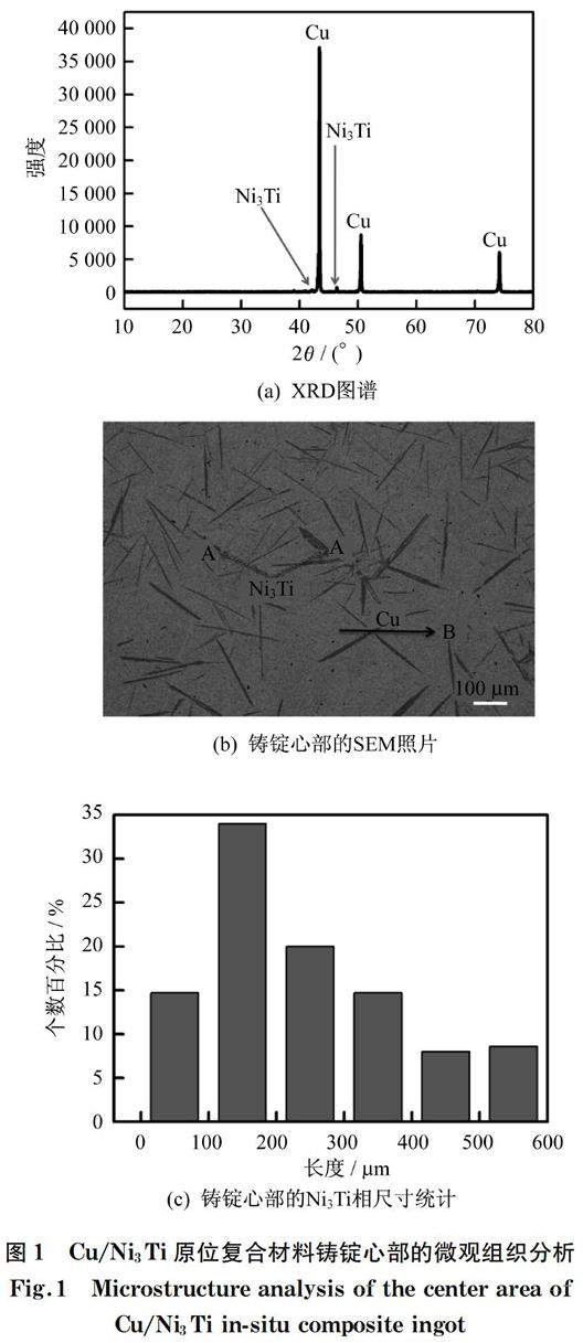
图1为复合材料的XRD图谱及SEM照片。由图1(a)所示的XRD图谱可以发现,复合材料中存在Cu和Ni3Ti两相。图1(b)为复合材料铸锭心部的SEM照片,从图中可明显看到针状第二相散乱分布于铜基体中,且具有非常清楚的界面。表1为图1(b)中A,B两点的能谱(EDS)分析。结合图1(b)和表1可发现,针状第二相(A点)的Ni,Ti原子比接近3∶1。结合XRD分析,可确定第二相为Ni3Ti相;基体为Cu,其中固溶了少量Ni,无Ti。图1(c)为铸锭心部Ni3Ti相的长度统计,经计算可知,铸锭心部Ni3Ti相的平均长度约249 μm。
表1 对应于图1(b)中A,B点的EDS分析
Tab.1 EDS analysis at the points A and B in Fig.1(b)
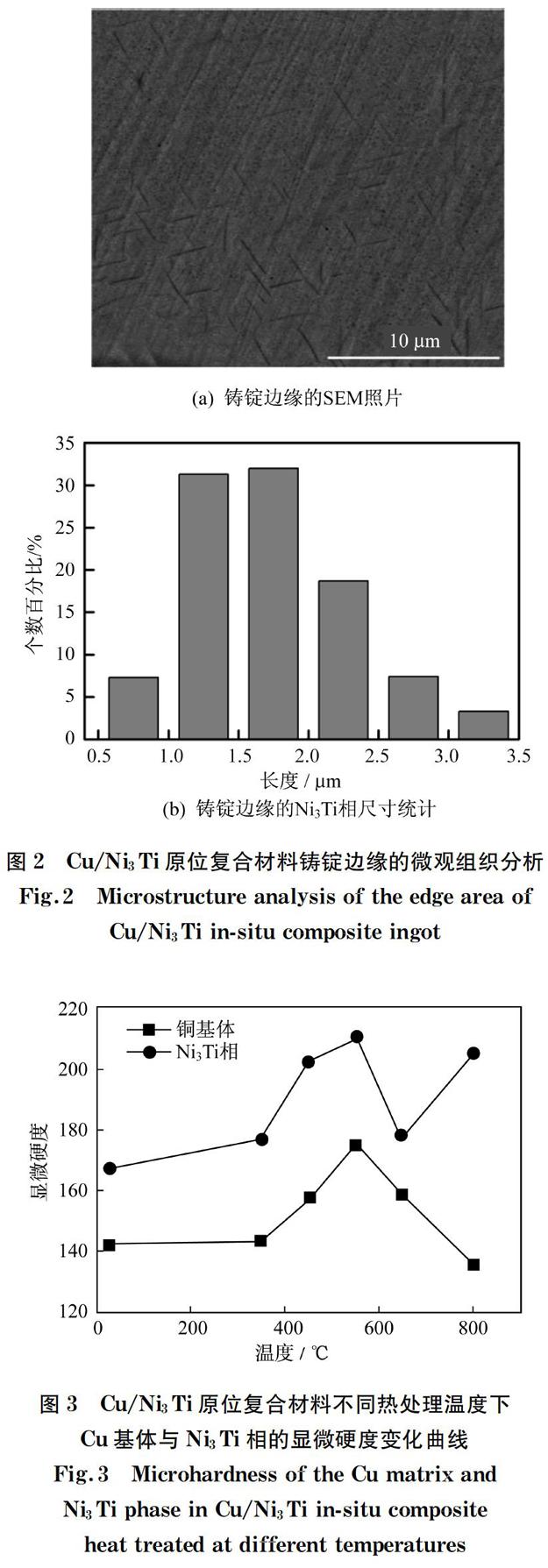
图2为铸锭边缘的显微组织分析。图2(a)为铸锭的SEM照片,从图中可以发现铸锭中存在大量针状Ni3Ti相。图2(b)为铸锭边缘Ni3Ti相的长度统计,经计算可知边缘Ni3Ti相的平均长度约1.74 μm。从图1(c)和图2(b)所示的第二相长度分布可发现Ni3Ti相大小不一,且尺寸相差较大:铸锭边缘Ni3Ti相的长度分布为0.5~3.5 μm,且超过60%的晶粒的尺寸集中在1~2 μm;铸锭心部Ni3Ti相的长度达到600 μm,长度分布为100~300 μm的Ni3Ti超过总数的50%。铸锭边缘和心部Ni3Ti相的长度相差较大,原因是液态金属凝固过程中,边缘部分冷却速度较快,因此得到尺寸细小的Ni3Ti相;而铸锭心部冷却速度较慢,因此Ni3Ti相尺寸较大。
图1 Cu/Ni3Ti原位复合材料铸锭心部的微观组织分析
Fig.1 Microstructure analysis of the center area of
Cu/Ni3Ti in-situ composite ingot
2.2 显微硬度
图3为不同温度时效20 h后Cu/Ni3Ti原位复合材料的显微硬度变化曲线。从图3中可明显看出:一方面,铜基体和Ni3Ti相的硬度均在550 ℃时效处理后获得最大值,且铜基体与Ni3Ti相显微硬度最大值分别达到了174和209;另一方面,铜基体的显微硬度要远小于Ni3Ti相的显微硬度,但高于通过放电等离子烧结(SPS)工艺制备的CuCr/CNTs复合材料的显微硬度(95.8)[35]。
图2 Cu/Ni3Ti原位复合材料铸锭边缘的微观组织分析
Fig.2 Microstructure analysis of the edge area of
Cu/Ni3Ti in-situ composite ingot
图3 Cu/Ni3Ti原位复合材料不同热处理温度下
Cu基体与Ni3Ti相的显微硬度变化曲线
Fig.3 Microhardness of the Cu matrix and
Ni3Ti phase in Cu/Ni3Ti in-situ composite
heat treated at different temperatures
2.3 弹性模量
在恒温24 ℃条件下,未经过热处理的Cu/Ni3Ti复合材料的弹性模量通过纳米压痕试验来表征,结果如图4所示。图4(a)为未经过热处理的复合材料的载荷-位移曲线,可以发现,在相同载荷下,Ni3Ti相的位移要远小于铜基体。图4(b)和(c)分别为Ni3Ti相与铜基体的弹性模量和硬度随位移的变化曲线,可以发现,未处理状态时的铜基体的最大弹性模量和硬度分别为153.5 GPa和2.1 GPa,Ni3Ti相的最大弹性模量和硬度分别为224 GPa和7.7 GPa。由上述数据可知,Ni3Ti相最大弹性模量约是铜基体的1.4倍,硬度约是铜基体的4倍,是理想的增强相。
图4 热处理前Cu/Ni3Ti原位复合材料的纳米压痕测试结果
Fig.4 Nanoindentation results of Cu/Ni3Ti in-situ composite before heat treatment
图5为Cu/Ni3Ti原位复合材料在800 ℃固溶和550 ℃时效后的纳米压痕测试结果。图5(a)和(b)为固溶与时效后的载荷-位移曲线。图5(c)和(d)分别为铜基体与Ni3Ti相的弹性模量、硬度与位移的关系曲线。由图5(c)可知,550 ℃时效处理后,Cu基体最大弹性模量和硬度分别为159.9 GPa和2.1 GPa;而800 ℃固溶后,铜基体最大弹性模量及硬度分别为154.8 GPa和2.0 GPa。相比热处理前的Cu/Ni3Ti原位复合材料,800 ℃固溶和550 ℃时效后,复合材料中铜基体的硬度更高,且550 ℃时效处理后铜基体的硬度最高,与显微硬度测试结果一致。图5(d)中的Ni3Ti相也是在热处理后获得了更大的弹性模量和硬度,分别达到249.7 GPa和10.5 GPa。
根据上述试验结果可知,Cu/Ni3Ti原位复合材料在550 ℃时效处理后获得了更高的硬度,原因是固溶强化及第二相强化共同作用的结果。当时效温度较高时,固溶原子增多,固溶强化增强,但第二相含量减少,第二相弥散强化的效果削弱,反之亦然。而在550 ℃时效处理后,第二相和固溶原子均保持了较好的强化作用,此时的强化效果最佳。
图5 Cu/Ni3Ti原位复合材料800 ℃固溶与550 ℃时效后的纳米压痕测试结果
Fig.5 Nanoindentation results of Cu/Ni3Ti in-situ composite after solid-solution at 800 ℃ and aging at 550 ℃
3 结 论
通过真空电弧熔炼得到Cu/Ni3Ti原位复合材料。通过显微组织、显微硬度及纳米压痕测试,得到如下结果。
(1) XRD结果显示,材料中含有Ni3Ti相及铜相;SEM分析得出,Ni3Ti相在铜基体中呈针状,且铸锭边缘Ni3Ti相尺寸较小,平均长度约1.74 μm,而心部Ni3Ti相平均长度约249 μm。
(2) 比较了不同温度热处理后的Cu/Ni3Ti原位复合材料的显微硬度,发现550℃时效后获得的硬度最大,铜基体与Ni3Ti相的显微硬度最大值分别达到了174和209。
(3) 纳米压痕测试得出,经热处理后的Cu/Ni3Ti原位复合材料中Ni3Ti相的最大彈性模量和硬度分别为249.7 GPa和10.5 GPa,而铜基体的最大弹性模量和硬度分别为159.9 GPa和2.1 GPa,Ni3Ti相的最大弹性模量和硬度分别约是铜基体的1.6倍和5.5倍,是较理想的增强相。
参考文献:
[1] LU K,CHEN X,HUANG X,et al.Revealing the maximum strength in nanotwinned copper[J].Science,2009,323(5914):607-610.
[2] MIURA H,NISHIYAMA N,INOUE A.Non-equilibrium copper-based crystalline alloy sheet having ultrahigh strength and good electrical conductivity[J].Journal of Alloys and Compounds,2011,509(S1):S361-S363.
[3] LOPEZ F,REYES J,CAMPILLO B,et al.Rapid solidication of copper alloys with high strength and high conductivity[J].Journal of Materials Engineering and Performance,1997,6(5):611-614.
[4] LU D P,WANG J,ZENG W J,et al.Study on high-strength and high-conductivity Cu-Fe-P alloys[J].Materials Science and Engineering A,2006,421(1/2):254-259.
[5] HOSSEINI S A,MANESH H D.High-strength,high-conductivity ultra-fine grains commercial pure copper produced by ARB process[J].Materials & Design,2009,30(8):2911-2918.
[6] WANG F L,LI Y P,WAKOH K,et al.Cu-Ti-C alloy with high strength and high electrical conductivity prepared by two-step ball-milling processes[J].Materials & Design,2014,61:70-74.
[7] SHUAI J,XIONG L Q,ZHU L,et al.Enhanced strength and excellent transport properties of a superaligned carbon nanotubes reinforced copper matrix laminar composite[J].Composites Part A:Applied Science and Manufacturing,2016,88:148-155.
[8] LUO H B,SUI Y W,QI J Q,et al.Copper Matrix composites enhanced by Silver/reduced Graphene Oxide hybrids[J].Materials Latters,2017,196:354-357.
[9] TAZEGUL O,DYLMISHI V,CIMENOGLU H.Copper matrix composite coatings produced by cold spraying process for electrical applications[J].Archives of Civil and Mechanical Engineering,2016,16(3):344-350.
[10] MA F C,LU S Y,LIU P,et al.Evolution of strength and fibers orientation of a short-fibers reinforced Ti-matrix composite after extrusion[J].Materials & Design,2017,126:297-304.
[11] MA F C,WANG T R,LIU P,et al.Mechanical properties and strengthening effects of in situ(TiB+TiC)/Ti-1100 composite at elevated temperatures[J].Materials Science and Engineering A,2016,654:352-358.
[12] MA F C,ZHENG B,LIU P,et al.Modeling of effects of thermomechanical processing on elevated-temperature mechanical properties of in situ(TiB+TiC)/Ti-1100 composite[J].Journal of Materials Science,2016,51(16):7502-7511.
[13] FRAGE N,FROUMIN N,RUBINOVICH L,et al.Inltrated TiC/Cu composites[C]∥15th International Plansee Seminar.Reutte:[s.n.],2001:202-216.
[14] NEMATI N,KHOSROSHAHI R,EMAMY M,et al.Investigation of microstructure,hardness and wear properties of Al-4.5 wt.% Cu-TiC nanocomposites produced by mechanical milling[J].Materials & Design,2011,32(7):3718-3729.
[15] BAGHERI G A.The effect of reinforcement percentages on properties of copper matrix composites reinforced with TiC particles[J].Journal of Alloys and Compounds,2016,676:120-126.
[16] MA F C,SHI Z B,LIU P,et al.Strengthening effect of in situ TiC particles in Ti matrix composite at temperature range for hot working[J].Materials Characterization,2016,120:304-310.
[17] BASU S N,HUBBARD K M,HIRVONEN J P,et al.Microstructure and stability of TiB2 and Cu multilayers[C]∥The Spring Meeting of the Materials Research Society.San Francisco,CA:Materials Research Society,1990:16-21.
[18] WANG T M,ZOU C L,CHEN Z N,et al.In situ synthesis of TiB2 particulate reinforced copper matrix composite with a rotating magnetic field[J].Materials & Design,2015,65:280-288.
[19] TU J P,WANG N Y,YANG Y Z,et al.Preparation and properties of TiB2 nanoparticle reinforced copper matrix composites by in situ processing[J].Materials Letters,2002,52(6):448-452.
[20] 陳渝,屠晓倩,王柳幸,等.纳米Al2O3颗粒对Cu-Al2O3性能的影响[J].有色金属材料与工程,2018,39(1):15-18.
[21] TAO J M,CHEN X F,HONG P,et al.Microstructure and electrical conductivity of laminated Cu/CNT/Cu composites prepared by electrodeposition[J].Journal of Alloys and Compounds,2017,717:232-239.
[22] HUANG Z X,ZHENG Z,ZHAO S,et al.Copper matrix composites reinforced by aligned carbon nanotubes:Mechanical and tribological properties[J].Materials & Design,2017,133:570-578.
[23] MA F C,PING L,WEI L,et al.The mechanical behavior dependence on the TiB whisker realignment during hot-working in titanium matrix composites[J].Sci Rep,2016,6:36126.
[24] MA F C,LU S Y,LIU P,et al.Microstructure and mechanical properties variation of TiB/Ti matrix composite by thermo-mechanical processing in beta phase field[J].Journal of Alloys and Compounds,2017,695:1515-1522.
[25] YAO G C,MEI Q S,LI J Y,et al.Cu/C composites with a good combination of hardness and electrical conductivity fabricated from Cu and graphite by accumulative roll-bonding[J].Materials & Design,2016,110:124-129.
[26] HAN T L,LI J J,ZHAO N Q,et al.In-situ fabrication of nano-sized TiO2 reinforced Cu matrix composites with well-balanced mechanical properties and electrical conductivity[J].Powder Technology,2017,321:66-73.
[27] ZHOU D S,ZENG W,ZHANG D L.A feasible ultrafine grained Cu matrix composite microstructure for achieving high strength and high electrical conductivity[J].Journal of Alloys and Compounds,2016,682:590-593.
[28] MAKI K,ITO Y,MATSUNAGA H,et al.Solid-solution copper alloys with high strength and high electrical conductivity[J].Scripta Materialia,2013,68(10):777-780.
[29] GORSSE S,OUVRARD B,GOUN M,et al.Microstructural design of new high conductivity-high strength Cu-based alloy[J].Journal of Alloys and Compounds,2015,633:42-47.
[30] ZHANG B B,TAO N R,LU K.A high strength and high electrical conductivity bulk Cu-Ag alloy strengthened with nanotwins[J].Scripta Materialia,2017,129:39-43.
[31] LI D M,WANG Q,JIANG B B,et al.Minor-alloyed Cu-Ni-Si alloys with high hardness and electric conductivity designed by a cluster formula approach[J].Progress in Natural Science:Materials International,2017,27(4):467-473.
[32] 葛繼平.形变Cu-Fe原位复合材料[D].大连:大连交通大学,2004.
[33] 丁丁.原位纳米颗粒增强铜合金的制备及其强化机制研究[D].北京:北京科技大学,2015.
[34] 刘克明.高强高导形变Cu基原位复合材料研究[D].长沙:中南大学,2012.
[35] 付少利,刘平,陈小红,等.SPS工艺对CuCr/CNTs复合材料组织性能的影响[J].有色金属材料与工程,2017,38(2):78-84.