叶片安放角对轴流泵马鞍区运行特性的影响
2018-09-03吴贤芳陆友东谈明高刘厚林
吴贤芳,陆友东,谈明高,刘厚林
叶片安放角对轴流泵马鞍区运行特性的影响
吴贤芳1,陆友东2,谈明高2,刘厚林2
(1.江苏大学能源与动力工程学院,镇江 212013;2. 江苏大学流体机械工程技术研究中心,镇江 212013)
为分析叶片安放角对轴流泵马鞍区工况运行特性的影响,以比转速822的轴流泵为研究模型,试验测试了不同叶片安放角下的运行特性。研究表明:随着叶片安放角的增大,模型泵最优工况处的扬程、流量和效率均逐渐增大,-4°到+4°的增幅分别为10.4%,26.7%和0.87%;不同安放角下,泵扬程曲线均存在明显的马鞍区;随着叶片安放角的增大,试验泵马鞍区的绝对位置向右上方偏移,但相对位置仍主要位于0.5BEP~0.6BEP(BEP为最高效率点对应的额定流量),且均在0.55BEP时扬程达到最小值;随着叶片安放角的减小,马鞍区内相对扬程在逐渐增大,马鞍区驼峰特性有所改善;随着叶片安放角的增大,各个安放角下马鞍区范围内的压力脉动较最优工况下更剧烈;叶轮进口压力脉动主频为叶片通过频率,泵出口处压力脉动主要受导叶影响,随流量减小逐渐向高频移动;随着叶片安放角的增大,叶轮进口和泵出口处主频处的压力脉动幅值均逐渐增大,在叶轮进口处,0.6BEP和0.55BEP时压力脉动幅值最大增幅分别达1.78和1.65倍,在泵出口处,正安放角下压力脉动幅值相对负角度有所增大;内流分析表明小流量工况下叶轮进口存在回流现象,叶轮出口靠近轮毂处有明显旋涡,导致小流量下压力脉动幅值增大。
泵;压力;叶片;轴流泵;叶片安放角;马鞍区;水力特性
0 引 言
轴流泵是一种低扬程泵,主要依靠叶轮的旋转对液体产生的作用力使液体沿轴线方向输送,广泛应用于南水北调、引嫩入白和三河三湖污染防治等国内重大水利工程[1-3],在农业灌溉排涝、水环境治理、城市供水工程和生态需水工程等方面也发挥着不可替代的作用[4-6]。
轴流泵在启动或停机过程中一般都会经过流量扬程曲线的马鞍区[7-9],此时泵会伴随有剧烈的振动噪声[10-12],严重影响泵的运行稳定性和泵站系统的安全性[13-15],长时间处于这种状态会严重影响泵的寿命[16-18]。因此,轴流泵马鞍区的特性研究一直是行业热点。
成立等[19]认为水力不稳定区的产生是由轴流泵旋转失速与进水条件恶化导致的。刘竹青等[20]对弯掠叶片和原型叶片高速轴流泵进行全三维流道数值模拟,发现合理的弯掠叶片可有效改善原型叶片轴流泵出现的“驼峰区”。刘君等[21]结合不同工况的数值模拟,对模型泵的马鞍形特性进行了分析,发现造成轴流泵装置模型效率下降和运行不稳定的直接原因是叶轮进口轮缘和叶轮出口轮毂的二次回流。茅媛婷等[22]通过数值模拟和试验相结合的方法对轴流泵进行了研究,发现马鞍形区存在于大约50%~65%的设计流量区域。程千等[23]研究了前置导叶对轴流泵小流量工况下马鞍区回流涡特性的影响,发现小流量工况下大量螺旋形回流出现在进水流道,在剪切作用下与主流相互影响形成回流涡,引起泵内能量损失,导致泵的水力特性下降。郑源等[24]基于标准-湍流模型和SIMPLEC算法,对轴流泵装置马鞍区的流动特性进行了研究,发现小流量工况下,叶轮出口处存在大量的回流和旋涡,并伴随着激烈的能量交换,导致轴流泵装置出现马鞍形区。宋希杰等[25]结合fluent非定常计算和模型试验研究了轴流泵进水漩涡对压力脉动的影响,发现叶轮进口断面处的压力脉动与进水漩涡诱发的脉动之间存在同步性,漩涡影响着叶轮内的压力脉动。石丽建等[26]采用CFD计算结合试验研究对轴流泵叶片进行多工况优化设计,研究结果使3个工况点的效率均有所提高,降低了运行成本,缩短了优化设计周期。谢荣盛[27]利用高速摄影试验和CFD仿真计算研究轴流泵失速形成的机理,发现轴流泵的流量扬程和流量轴功率曲线出现拐点的原因是叶轮外侧进口的诱导速度增大,导致叶轮进口冲角变小。Miyabe等[28]采用PIV技术进行研究,发现在马鞍区工况轴流泵运行不稳定性问题十分突出。Goltz等[29-30]利用油流技术和高速摄影技术研究发现小流量工况下泵内出现漩涡是导致泵内压力脉动剧烈、性能下降的主要原因。Shigemitsu等[31]使用LDV技术测量了高比转速轴流泵前后转子之间的流场,揭示了水从前转子流向后转子的流动规律,提出了一种轴流泵设计方案。
虽然目前有关轴流泵马鞍区运行特性的研究比较多,但叶片安放角对马鞍区特性的影响的研究还比较少。本文采用试验和CFD数值计算相结合的方法对马鞍区内轴流泵的能量特性和压力脉动特性进行了分析,研究了叶片安放角改变后轴流泵马鞍区运行特性的变化,研究结果可为提高轴流泵在小流量工况下的运行稳定性提供一定的参考。
1 试验模型
1.1 试验对象
以比转速s=822的轴流泵作为研究对象,其设计参数为流量d=0.33 m3/s、转速=1 450 r/min、扬程=6.05 m、比转速s=822、叶片数=4、导叶叶片数d=6。模型泵的主要结构参数:叶轮直径=300mm,轮毂直径h=135 mm。叶片安放角为叶片安置在轮毂上的角度,试验中叶轮原叶片安放角为0°,安放角通过叶片旋转进行调节;叶片安放角调节共有+4°、+2°、−2°和−4°等4个方案,其中正号表示逆时针旋转叶片,负号反之。叶轮实物如图1所示。

图1 叶轮模型
1.2 试验系统
试验在江苏大学国家水泵研究中心实验室进行,试验装置主要由汽蚀罐、模型泵、出水罐、增压泵、稳压罐、进水罐、电磁流量计、压力传感器等组成,试验台结构如图2所示。
流量用开封仪表有限公司MF/C3511021100CR102电磁流量计测量,精确度为 0.3%;进出口压力用上海威尔泰仪器仪表有限公司WT2000智能压力变送器测量,精度等级为0.1级非线性:≤±0.1%F.S(量程比<10:1);转速由希玛公司型号为AR926激光转速测量仪确定,分辨率为1 r/min,测量精度为0.1%;扭矩采用湘仪动力测试仪器有限公司JW-3扭矩仪和JC型转矩转速传感器测量,测量精度为±0.1% F.S;压力脉动传感器采用成都泰斯特电子信息有限责任公司CY200数字压力脉动传感器,传感器采样频率1 000 Hz,综合精度0.1%FS。
对轴流泵叶轮进口测点P1和泵出口测点P2的压力脉动信号进行测试,压力脉动测点如图3所示。

1.电动机 2.试验泵 3.进口测压孔 4.出口测压孔 5.电动阀 6.汽蚀罐 7.电动阀 8.流量计 9.稳压罐 10.增压泵
1.Electromotor 2.Test pump 3.Inlet pressure measurement hole 4.Onlet pressure measurement hole 5.Electric valve 6.Cavitation tank 7.Electric valve 8.Flowmeter 9.Steadying pressure-pump 10.Booster pump
注:汽蚀罐外接真空泵。
Notice: Cavitation tank is connected with the vacuum pump.
图2 模型泵测试试验台
Fig.2 Test rig of model pump

注:P1为轴流泵叶轮进口测点,P2为泵出口测点。
2 试验结果分析
2.1 能量特性曲线
图4给出了不同叶片安放角下泵的能量特性曲线。从图4中可以看出,叶片安放角为+4°、+2°、−2°和−4°时,各个安放角下最高效率点分别位于0.364、0.34、0.299和0.273m3/s流量工况;+4°和+2°最优工况处流量较叶片安放角为0°时分别提高了15.5%和9.8%,−2°和−4°时最优工况处流量较叶片安放角为0°时分别降低了5%和13.3%。从−4°变化到+4°最优工况处扬程、流量和效率分别增大了10.4%、26.7%和0.87%。
图4中扬程的增加是由于随着叶片安放角的增大,叶轮出口速度的圆周分量增加,根据泵的基本方程(1)可知,扬程必定会增加;随着叶片安放角的增大,叶片液流轴面速度也在增加,因此流量也会增大。
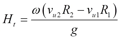
式中Ht为理论扬程,m;ω为叶片旋转角速度,rad/s;vu2为叶轮出口绝对速度圆周分量,m/s;R2为叶轮出口半径,m;vu1为叶轮进口绝对速度圆周分量,m/s;R1为叶轮进口半径,m;g为重力加速度,g=9.8 m/s2。
图4表明各个安放角下模型泵-曲线均存在明显的马鞍区,并且随着叶片安放角的增大,马鞍区逐渐向右上方偏移。统计了不同叶片安放角下马鞍区相对区域,如表1所示。
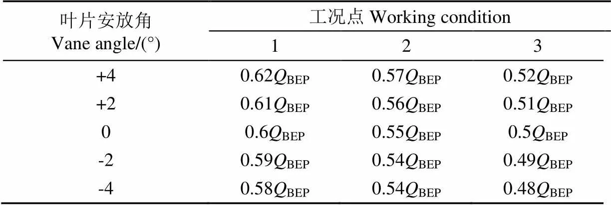
表1 不同叶片安放角下马鞍区范围
注:BEP为最高效率点对应的额定流量,-4°到+4°分别为0.364、0.34、0.33、0.299和0.273 m3·s-1。叶片安放角正号表示逆时针旋转叶片,负号反之。
Note:BEPrepresents rated flow when efficiency reaches the maximum, andBEPare 0.364, 0.34, 0.33, 0.299 and 0.273 m3·s-1from -4° to +4° respectively. The positive vane angles represent that the blade is rotated counterclockwise, and the negative is reversed.
由表1可知,随着叶片安放角的增大,马鞍区的相对位置发生了一定的改变,但变化幅度比较小,基本可以认为马鞍区范围仍在0.5BEP~0.6BEP区间内,且在0.55BEP附近工况下扬程在马鞍区内达到最小值。
为了衡量马鞍区内驼峰程度,引入“相对扬程系数”的概念,其定义为:各角度下马鞍区最低点0.55BEP处的扬程与最优工况扬程的比值,该值越大越说明泵的马鞍区驼峰较小。
叶片安放角为+4°、+2°、0°、−2°和−4°时的相对扬程系数分别为1.69、1.96、2.08、2.43、2.85,可见随着叶片安放角的减小,相对扬程系数在逐渐增大,说明随着叶片安放角的减小,马鞍区驼峰情况有所改善。
综合以上分析,随着叶片安放角的增大,马鞍区的绝对位置向右上方偏移,但马鞍区的相对位置仍主要位于0.5BEP~0.6BEP流量范围内;叶片安放角的减小可以改善马鞍区的驼峰程度。
2.2 叶轮进口的压力脉动特性分析
2.2.1 压力脉动特性时域分析
为了进一步分析叶片安放角对轴流泵内压力脉动的影响,对0.55BEP、0.6BEP和1.0BEP3个不同工况下轴流泵叶轮进口P1点的压力脉动信号进行时域分析,轴流泵叶轮旋转一圈的时间为,用表示时间内周期的个数,则=/。用压力脉动系数p来表示压力脉动幅值。
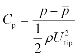
图5为叶片安放角+4°、+2°、0°、−2°和−4°时叶轮进口P1处压力脉动时域图。由图6可知,不同叶片安放角时最优工况下叶轮进口P1处的压力脉动单个周期内4波峰4波谷的特征比较明显,与叶轮叶片数相同,故叶轮进口处压力脉动主要受叶轮影响。
图5中各安放角下叶轮进口P1处的压力脉动峰峰值随着流量的减小逐渐增大;1.0BEP到0.6BEP工况时,各叶片安放角下压力脉动峰峰值变化较小;0.6BEP到0.55BEP工况时,各个叶片安放角下的压力脉动峰峰值变化剧烈,这是由于随着流量的减小泵内出逐渐现了回流和失速等不稳定流动,使得泵内部流动状态进一步恶化,从而导致压力波动更加剧烈。
2.2.2 压力脉动特性频域分析
对压力脉动时域信号进行傅里叶变换,分析其频率成分。压力脉动传感器采样频率s为1 000 Hz,取=10 000个采样点的数据进行傅里叶分析,频率分辨率D=s/=0.1 Hz。试验泵叶轮叶片数为4,导叶叶片数6,转速为1 450 r/min,因此叶频(blade passing frequency,BPF)为96 Hz,轴频(axial passing frequency,APF)为24 Hz。用p代表叶频,n代表轴频,p=4n。图6为叶轮进口P1处在不同叶片安放角下的压力脉动频域图。
由图6可知,在马鞍区工况内,各安放角下压力脉动幅值较最优工况明显增大,随着叶片安放角的增大,叶轮进口P1处出现更多的低频脉动;不同流量各个叶片安放角下压力脉动峰值主要位于轴频p及其谐频处,且不同叶片安放角下压力脉动的主频均为叶频p;随着叶片安放角的增大,不同流量工况下主频处的压力脉动幅值均逐渐增大,0.6BEP时压力脉动幅值最大增幅达1.78倍,0.55BEP时压力脉动幅值最大增幅达1.65倍。
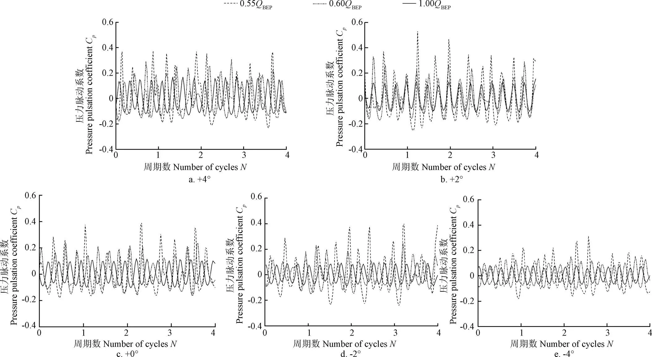
图5 不同叶片安放角下叶轮进口P1处压力脉动时域图

图6 多工况下叶轮进口P1处压力脉动频域图
2.3 泵出口压力脉动特性分析
2.3.1 压力脉动时域分析
图7为叶片安放角+4°、+2°、0°、-2°和-4°时泵出口P2处压力脉动时域图。由图7可知,与叶轮进口相似,不同叶片安放角时最优工况下泵出口P2处压力脉动曲线为规则的正弦波形,各个周期内同样存在4波峰4波谷特性;泵出口P2处的压力脉动峰峰值随着流量的减小逐渐增大;马鞍区内压力脉动峰峰值明显大于最优工况下,且马鞍区内的波动规律性较差;随着叶片安放角的增大,0.6BEP工况下的压力脉动波动变得剧烈,0.55BEP工况下压力脉动出现先增大后减小的趋势。
图7中各安放角下泵出口的压力脉动峰峰值较叶轮进口处明显降低,这应该是由于导叶对流体的整流作用。随着相对流量的减小,各安放角下压力脉动峰峰值在逐渐增大;随着叶片安放角的增大,泵出口处的压力脉动峰峰值也逐渐增大,压力脉动变得剧烈。
2.3.2 压力脉动频域分析
图8为不同叶片安放角下泵出口P2的压力脉动频域图。从图8可以看出,泵出口处主频随流量减小逐渐向高频移动;马鞍区工况下压力脉动主频基本稳定在6倍轴频(axial passing frequency),次频稳定在4倍轴频(axial passing frequency),说明了泵出口压力脉动主要受导叶的影响,同时也受叶轮的影响;随着叶片安放角的增大,马鞍区工况内泵出口处的低频脉动变化剧烈,与叶轮进口一致,表明泵出口的压力脉动受着叶轮处流动分离的影响;随着相对流量减小至马鞍区,同一叶片安放角下压力脉动的幅值明显增大,这可能是由于流量减小时出水弯管内产生的旋涡导致的;正安放角下压力脉动幅值相对负角度有所增大,叶片安放角为-4°,-2°,+2°和+4°时最优工况下压力脉动幅值分别为0°的0.32,0.32,0.56和0.76倍,马鞍区最低点0.55BEP下压力脉动幅值分别为0°的0.66,0.48,0.47和0.82倍,这可能是因为随着叶片安放角的增大,流体轴面速度增大,过流面积增大,泵出口处螺旋出流加剧,导致压力脉动的增幅。

图7 不同叶片安放角下泵出口P2处压力脉动时域图

图8 多工况下泵出口P2处压力脉动频域图
3 泵内CFD内流分析
为了进一步分析泵内压力脉动的变化规律,图9给出了叶片安放角为0°时的模型泵叶轮内不同工况下的流线分布。从图9可以清晰地看出,在最优工况下,叶轮内部流线分布较均匀。到0.6BEP工况,模型泵开始进入马鞍区,由于流动分离在叶轮进口前靠近轮缘处出现了回流,同时在叶轮出口靠近轮毂处产生了较大的涡,说明了此时泵内已经出现了很多不稳定流动;0.55BEP工况较0.6BEP工况叶轮进口前的回流明显加强,同时叶轮出口靠近轮毂处的涡逐渐扩大,接近失速。因此,在小流量工况下叶轮进口存在着回流现象,叶轮出口靠近轮毂处存在着明显旋涡,这就导致了小流量下模型泵内部流动状态紊乱,轴流泵内部压力脉动变得剧烈。
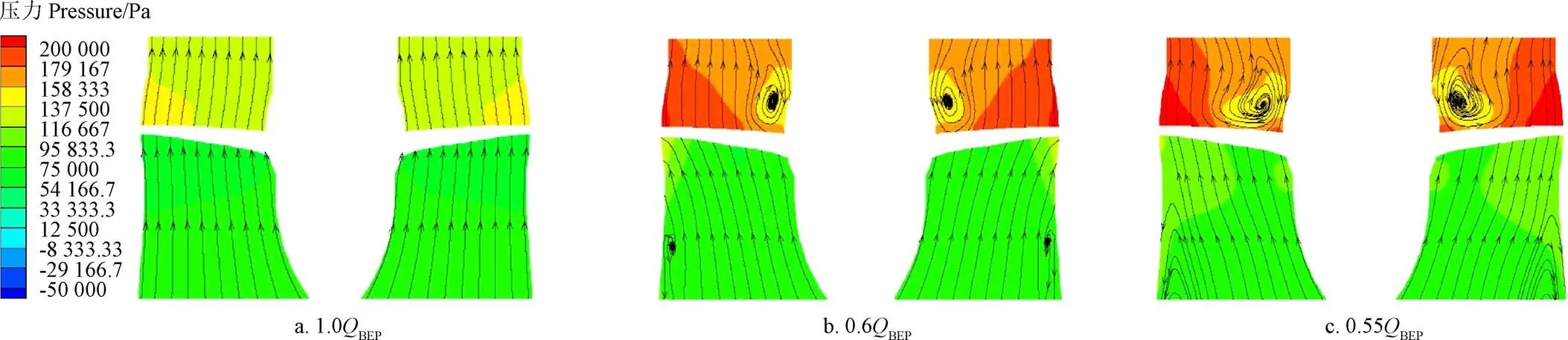
图9 叶片安放角为0°时叶轮流线分布
4 结论与讨论
1)随着叶片安放角的增大,轴流泵马鞍区内的扬程、流量和效率均逐渐增大,从−4°变化到+4°,最优工况处扬程、流量和效率分别增大了10.4%、26.7%和0.87%;+4°和+2°最优工况处流量较0°安放角下分别提高了15.5%和9.8%,−2°和−4°时最优工况处流量较0°安放角下分别降低了5%和13.3%。
2)随着叶片安放角的增大,试验泵马鞍区逐渐向右上方偏移,且均在0.55BEP附近工况扬程达到最小值;随着叶片安放角的减小,马鞍区驼峰特性有所改善。
3)在0.55BEP~0.6BEP即马鞍区范围内,各个安放角下的压力脉动较最优工况下更剧烈;叶轮进口压力脉动主频为叶片通过频率,泵出口处主要受导叶影响;各安放角下泵出口处压力脉动幅值较叶轮进口处明显降低。
4)在马鞍区工况下,随着叶片安放角的增大,叶轮进口和泵出口处主频处的压力脉动幅值均逐渐增大,在叶轮进口处,0.6BEP和0.55BEP时压力脉动幅值最大增幅分别达1.78和1.65倍,在泵出口处,正安放角下压力脉动幅值相对负角度有所增大。
5)小流量工况下叶轮进口存在回流现象,叶轮出口靠近轮毂处存在旋涡,使小流量下压力脉动幅值增大。
本文主要研究了轴流泵马鞍区内的能量特性和压力脉动特性,但研究还存在很多不足,未来建议采用三维粒子图像测速和高速摄影技术对马鞍区内流场进行试验测试。
[1] 徐磊,陆林广,陈伟,等. 南水北调工程邳州站竖井贯流泵装置进出水流态分析[J]. 农业工程学报,2012,28(6):50-56.
Xu Lei, Lu Linguang, Chen Wei, et al. Flow pattern analysis on inlet and outlet conduit of shaft tubular pump system of Pizhou pumping station in South-to-North Water Diversion Project[J]. Transactions of the Chinese Society of Agricultural Engineering (Transactions of the CSAE), 2012, 28(6): 50-56. (in Chinese with English abstract)
[2] 张德胜,施卫东,张华,等. 轴流泵叶轮端壁区流动特性数值模拟[J]. 农业机械学报,2012,43(3):73-77.
Zhang Desheng, Shi Weidong, Zhang Hua, et al. Nurnerical simulation of flow field characteristics in tip clearance region of axial-flow impeller[J]. Transactions of the Chinese Society for Agricultural Machinery, 2012, 43(3): 73-77. (in Chinese with English abstract)
[3] 陆林广,伍杰,陈阿萍,等. 立式轴流泵装置的三维湍流流动数值模拟[J]. 排灌机械工程学报,2007,25(1):29-32.
Lu Linguang, Wu Jie, Chen Aping, et al. Numerical simulation of 3D turbulent flow in a vertical axial-flow pump system[J]. Journal of Drainage & Irrigation Machinery Engineering, 2007, 25(1): 29-32. (in Chinese with English abstract)
[4] 关醒凡. 轴流泵与斜流泵[M]. 北京:中国宇航出版社,2009.
[5] Badr H M, Ahmed W H. Axial Flow Pumps[M]. United States : John Wiley & Sons Ltd,2014: 205-220.
[6] Stepanoff A J. Centrifugal and Axial Flow Pumps[J]. Van Chong Book Company, 1950, 15(11): 678-683.
[7] Spencer E A. The performance of an axial-flow pump[J]. Proceedings of the Institution of Mechanical Engineers, 1956, 170(1): 874-908.
[8] 刘君,华学坤,郑源,等. 低扬程立式轴流泵装置模型马鞍形区研究[J]. 南水北调与水利科技,2011,9(4):34-38.
Liu Jun, Hua Xuekun, Zheng Yuan, et al. Study on performance of saddle zone in low lift vertical axial-flow pump system model[J]. South-to-North Water Transfer and Water Science & Technology, 2011, 9(4): 34-38. (in Chinese with English abstract)
[9] 王福军,张玲,张志民,等.轴流泵不稳定流场的压力脉动特性研究[J].水利学报,2007,38(8):1003-1009.
Wang Fujun, Zhang Ling, Zhang Zhimin, et al. Analysis on pressure flucuation of unsteady flow in axial flow pump [J]. Journal of Hydraulic Engineering, 2007, 38(8): 1003-1009. (in Chinese with English abstract)
[10] 钱忠东,王凡,王志远,等. 可调导叶式轴流泵马鞍区水力特性试验研究[J]. 排灌机械工程学报,2013,31(6):461-465.
Qian Zhongdong, Wang Fan, Wang Zhiyuan, et al. Experimental study on hydraulic performance of saddle zone in axial flow pump with adjustable guide vane[J]. Journal of Drainage & Irrigation Machinery Engineering, 2013, 31(6): 461-465. (in Chinese with English abstract)
[11] Li S C. Cavitation of Hydraulic Machinery[M]. London: Imperial College Press, 2000: 492.
[12] Pettigrew M J, Taylor C E. Two-phase flow-induced vibration: An overview[J]. Transactions-American Society of Mechanical Engineering Journal of Pressure Vessel Technology, 1994, 116(3): 233-253.
[13] Yoshida Y, Murakami Y, Tsurusaki H, et al. Rotating stalls in centrifugal impeller/vaned diffuser system: 1st report, experiment[J]. Transactions of the Japan Society of Mechanical Engineers Part B, 1990, 56(530): 2991-2998.
[14] 耿卫明,刘超,汤方平. 轴流泵叶轮出口流场的3D-PIV测量[J]. 河海大学学报:自然科学版,2010,38(5):516-521.
Geng Weiming, Liu Chao, Tang Fangping. 3D-PIV measurements of flow fields at exit to impeller of an axial flow pump[J]. Journal of Hohai University:Natural Sciences, 2010, 38(5): 516-521. (in Chinese with English abstract)
[15] 周佩剑,王福军,姚志峰. 旋转失速条件下离心泵隔舌区动静干涉效应[J]. 农业工程学报,2015,31(7):85-90.
Zhou Peijian, Wang Fujun, Yao Zhifeng. Impeller-volute interaction around tongue region in centrifugal pump under rotating stall condition[J]. Transactions of the Chinese Society of Agricultural Engineering (Transactions of the CASE), 2015, 31(7): 85-90. (in Chinese with English abstract)
[16] Arndt R E A.Cavitation in fluid machinery and hydraulic structures[J]. Annual Review of Fluid Mechanics, 1981, 13(1): 273-326.
[17] Laborde R, Chantrel P, Mory M. Tip clearance and tip vortex cavitation in an axial flow pump[J]. Journal of Fluids Engineering, 1997, 119(3): 680-685.
[18] Wu C H. A general theory of three-dimensional flow in subsonic and supersonic turbomachines of axial,radial,and mixed-flow types[C]. ASME Paper Number 50-A-79, or NACA TN 2604, 1952: 1-90.
[19] 成立,吴璐璐,刘超,等. 大型轴流泵水力不稳定区研究[J].灌溉排水学报,2010,29(2):102-104.
Cheng Li, Wu Lulu, Liu Chao,et al. Hydraulic unstable operating region of large scale axial flow pump[J]. Journal of Irrigation and Drainage, 2010, 29(2): 102-104. (in Chinese with English abstract)
[20] 刘竹青,肖若富,吕腾飞,等. 弯掠叶片对轴流泵驼峰及空化性能的影响[J]. 排灌机械工程学报,2012,30(3):270-275.
Liu Zhuqing, Xiao Ruofu, Lü Tengfei, et al. Effect pf swept blade on hump and cavitation characteristics of axial flow pump[J]. Journal of Drainage & Irrigation Machinery Engineering, 2012, 30(3): 270-275. (in Chinese with Engish abstract)
[21] 刘君,华学坤,郑源,等. 低扬程立式轴流泵装置模型马鞍形区研究[J]. 南水北调与水利科技,2011,9(4):34-38.
Liu Jun, Hua Xuekun, Zheng Yuan, et al. Study on performance of saddle zone in low lift vertical axial-flow pump system model[J]. South to North Water Transfer and water conservancy technology, 2011, 9(4): 34-38. (in Chinese with English abstract)
[22] 茅媛婷,周大庆,郑源,等. 轴流泵马鞍区流动特性数值模拟及模型试验[J]. 工程热物理学报,2010,31(6):25-28.
Mao Yuanting, Zhou Daqing, Zheng Yuan, et al. Numerical simulation and model test of flow characteristics in saddle area of axial flow pump[J]. Journal of Engineering Thermophysics, 2010, 31(6): 25-28. (in Chinese with English abstract)
[23] 程千,冯卫民,周龙才,等. 前置导叶对轴流泵马鞍区工况回流涡特性的影响[J]. 农业机械学报,2016,47(4):8-14.
Cheng Qian, Feng Weimin, Zhou Longcai, et al. The influence of the front guide vane on the return vortex characteristics of the axial flow pump saddle area[J]. Transactions of the Chinese Society of Agricultural Machinery, 2016, 47(4): 8-14. (in Chinese with English abstract)
[24] 郑源,茅媛婷,周大庆,等. 低扬程大流量泵装置马鞍区的流动特性[J]. 排灌机械工程学报,2011,29(5):369-373.
Zheng Yuan, Mao Yuanting, Zhou Daqing, et al. Flow characteristics of low lift and large flow pump unit saddle area[J]. Journal of Drainage & Irrigation Machinery Engineering, 2011, 29(5): 369-373. (in Chinese with English abstract)
[25] 宋希杰,刘超,罗灿. 轴流泵装置进水漩涡对压力脉动的影响[J]. 农业机械学报,2018,49(2):113-120.
Song Jiexi, Liu Chao, Luo Can. Influence of inlet vortex on pressure pulsation in axial flow pump unit[J]. Transactions of the Chinese Society of Agricultural Machinery, 2018, 49(2): 113-120. (in Chinese with English abstract)
[26] 石丽建,汤方平,刘超,等. 轴流泵多工况优化设计及效果分析[J]. 农业工程学报,2016,32(8):63-69.
Shi Lijian, Tang Fangping, Liu Chao, et al. Optimization design and effect analysis of multi-operation conditions of axial-flow pump device[J]. Transactions of the Chinese Society of Agricultural Engineering (Transactions of the CSAE), 2016, 32(8): 63-69. (in Chinese with English abstract)
[27] 谢荣盛. 轴流泵小流量工况水力特性研宄[D]. 扬州:扬州大学,2016.
Xie Rongsheng. The Investigation of Small Flow Condition Hydraulic Performance in Axial Flow Pumps[D]. Yangzhou: Yangzhou University, 2016. (in Chinese with English abstract)
[28] Miyabe M, Maeda H, Umeki I, et al. Unstable head-flow characteristic generation mechanism of a low specific speed mixed flow pump[J]. Journal of Thermal Science, 2006, 15(2): 115-120.
[29] Goltz I, Kosyna G, Stark U, et al. Stall inception phenomena in a single-stage axial-flow pump[J]. Proceedings of the Institution of Mechanical Engineers Part a Journal of Power & Energy, 2003, 217(4): 471-479.
[30] Goltz I, Kosyna G, Wulff D, et al. Structure of the rotor tip flow in a highly loaded single-stage axial-flow pump approaching stall: Part II-Stall inception-Understanding the mechanism and overcoming its negative impacts[C]// ASME 2004 Heat Transfer/Fluids Engineering Summer Conference, Charlotte, 2004: 301-306.
[31] Shigemitsu T, Furukawa A, Watanabe S, et al. Experimental analysis of internal flow of contra-rotating axial flow pump[C]//Proceedings of the 8th International Symposium on Experimental and Computational Aerothermodynamics of Internal Flows, Lyon, 2007.
Effect of vane angle on axial flow pump running characteristics in saddle zone
Wu Xianfang1, Lu Youdong2, Tan Minggao2, Liu Houlin2
(1.,,212013,; 2.,,212013,)
In order to analyze the influence of the vane angle on the performance in saddle zone of the axial flow pump, the operation characteristics with different vane angles were tested by the axial flow pump with specific speed of 822 RPM. The research shows that with the increase of vane angle, the head, flow and efficiency of the test pump increase at the optimal working conditions at the same time, and the increase ranges are 10.4%, 26.7% and 0.87% respectively when vane angle changes from -4° to +4°. Under different vane angles, the head curves all present obvious saddle area. With the increase of the vane angle, the coefficient of relative head decreases gradually. It shows that the performance of saddle area is improved with the decrease of the vane angle. The absolute position in the saddle zone of the test pump deviates to the upper right, but the relative position is still mainly located in the range of 0.5BEP-0.6BEP(BEPis the flow when efficiency reaches the maximum), and the head reaches a minimum at 0.55BEP. The pressure pulsation at monitoring point of impeller inlet under different vane angels is obvious with the feature of 4 peaks and 4 troughs in a single cycle. Under the optimal operating conditions, the pressure fluctuation curve at monitoring point of pump outlet is a regular sine wave, and there are also 4 wave peaks and 4 wave valleys in each cycle, and the peak value of pressure fluctuating peak at monitoring point of pump outlet increase with the decrease of flow rate. With the change of vane angles, the peak value of the pressure fluctuating peak in the saddle area is obviously larger than the optimal operating condition at the monitoring points ofimpeller inlet and pump outlet. With the increase of the vane angle, the pressure fluctuation in the 0.6BEPbecomes intense, and the pressure fluctuation in the 0.55BEPincreases first and then decreases. When the vane angle increases, the flow rate at monitoring point of impeller inlet decreases and when the flow changes from 1.0BEPto 0.6BEP, the peak value of the pressure fluctuating peak changes gradually, and the pressure fluctuating peak value of each angle changes violently as the flow changes from 0.6BEPto 0.55BEP. With the decrease of the relative flow, the pressure pulsation under different vane angles increases gradually. When the relative flow reached the range of saddle area, the amplitude of low frequency pulsation increases gradually, and when the flow rate continues to decrease, the broadband frequency distribution moves to the low frequency band, and the amplitude of low frequency increases. The main frequency of pressure pulsation at the pump outlet in the saddle area is basically stable at 6 APF (axial passing frequency) and the secondary frequency is stable at 4 APF. It shows that the pressure pulsation of the pump outlet is mainly influenced by the guide vane, and is also influenced by the blade passing frequency. The main frequency of the pressure pulsation at impeller inlet is the blade passing frequency, as the main frequency at the pump outlet is the guide vane passing frequency, and it moves to high frequency with the decrease of flow gradually. With the increase of the vane angle, the amplitudes of main frequency of pressure fluctuation at the impeller inlet, guide vane and pump outlet all gradually increase. At the impeller inlet, the maximum amplitudes of pressure fluctuation at 0.6BEPand 0.55BEPwere 1.78 and 1.65 times respectively, and at the outlet of the pump, the amplitude of pressure pulsation at the positive angles is increased relative to the negative angles. Finally, the results of numerical simulation show that there is a backflow phenomenon at the impeller inlet under the small flow condition, and the vortex near the hub leads to the increase of the pressure fluctuation amplitude in the small flow condition.
pumps; pressure; blades; axial flow pump; vane angle; saddle zone; hydraulic performance
2018-01-21
2018-06-15
国家自然科学基金资助项目(51509109,51779108);江苏省自然科学基金(BK20161350);江苏省现代农业重点研发计划(BE2017356);江苏高校优势学科建设工程资助项目(PAPD)
吴贤芳,副教授,主要研究方向现代泵理论设计与方法。Email:wxftmg@ujs.edu.cn
10.11975/j.issn.1002-6819.2018.17.007
TH312
A
1002-6819(2018)-17-0046-08
吴贤芳,陆友东,谈明高,刘厚林. 叶片安放角对轴流泵马鞍区运行特性的影响[J]. 农业工程学报,2018,34(17):46-53. doi:10.11975/j.issn.1002-6819.2018.17.007 http://www.tcsae.org
Wu Xianfang, Lu Youdong, Tan Minggao, Liu Houlin. Effect of vane angle on axial flow pump running characteristics in saddle zone[J]. Transactions of the Chinese Society of Agricultural Engineering (Transactions of the CSAE), 2018, 34(17): 46-53. (in Chinese with English abstract) doi:10.11975/j.issn.1002-6819.2018.17.007 http://www.tcsae.org