Simulation of Solid Particle Interactions Including Segregated Lamination by Using MPS Method
2018-08-13KyungSungKimMooHyunKimHakunJangandHeeChenCho
Kyung Sung Kim, Moo-Hyun Kim , Hakun Jangand Hee Chen Cho
Abstract: A new MPS (Moving Particle Semi-implicit) method is developed to simulate the behaviors and interactions of multiple fine solid particles as a continuum. As fluid particles are affected by viscosity, so solid particles are affected by friction. The solid particle dynamics for landslides, dumping, and gravity sorting etc. which can be difficult to simulate using conventional MPS methods, are modeled in this paper using the developed multi-solid-particle MPS method that benefits from drawing comparisons with the corresponding fluid particle behaviors. The present MPS results for dumping solid particles are verified against the corresponding DEM (Discrete Element Method) results.The shape and angle of repose for solid particles are shown to be highly dependent on the friction coefficient between grains. The peculiar phenomenon of segregated lamination(gravity sorting) among grains of different densities has been successfully reproduced using the multi-solid-particle MPS method. Lamination quality is found to be dependent on the densities and frictional coefficients of the constituent particles. The behavior of heterogeneous mixtures of multiple solid and liquid particles are also compared and discussed. This newly developed tool offers a window into the physical dynamics of sedimentology that the broader geoscience community might benefit from.
Keywords: Fine solid particle, MPS (Moving Particle Semi-implicit), friction force, land sliding, dumping, segregated lamination, heterogeneous multiple particles, gravity sorting.
1 Introduction
CFD (Computational fluid dynamics) has benefited greatly over the past decades from improved algorithms and hardware capabilities. Three approaches to the field of CFD have emerged. The conventional Eulerian approach employs a fixed-grid system as its computational domain. The Lagrangian approach is grid-less and assigns physical properties to the representative particles. The third approach is a hybrid method that employs both Eulerian and Lagrangian system. There are advantages and disadvantages to each.
The conventional Eulerian CFD method uses control volume and is superior in computational efficiency but introduces other difficulties. The fixed grid system is inferior for modeling free surface, especially in cases that involve large deformations of interfaces and the associated coalescence and fragmentation. The hybrid approach takes advantage of the Eulerian and Lagrangian methods, but is still complicated from a computational standpoint. Because the fully Lagrangian approach is truly a grid-less particle system, and is simpler, more straightforward, and better-suited for highly nonlinear free-surface/interface problems, it will be the focus for this paper.
Within the fully Lagrangian system is two different methodologies: (1) the Moving Particle Semi-implicit (MPS) and (2) the Smoothed Particle Hydrodynamics (SPH)approaches. A detailed description of these, including methodology and comparisons of results, can be found in Bakti et al. [Bakti, Kim, Kim et al. (2016)].
The MPS method was originally introduced by Koshizuka et al. [Koshizuka and Oka(1996)], and was subsequently developed with improved algorithms by Gotoh [Gotoh(2009)] and Lee et al. [Lee, Park, Kim et al. (2011)]. Simulation accuracy was enhanced in the work of Tanaka et al. [Tanaka and Masunaga (2010)] and Lee et al. [Lee, Park,Kim et al. (2011)] through successfully suppressing non-physical pressure perturbations by introducing a multi-source term for the Poisson equation and using multiple-criteria in searching free-surface particles. Nomura et al. [Nomura, Koshizuka, Oka et al. (2001)]and Shirakawa et al. [Shirakawa, Horie, Yamamoto et al. (2001)] contributed to the modeling of surface tension and buoyancy corrections in multi-phase problems. Further refinements were added by Khayyer et al. [Khayyer and Gotoh (2013)] who introduced density-averaging near the interfaces of large density differences. Shakibaenia et al.[Shakibaenia and Jin (2012)] used a similar averaging method for MPS to address the problem of instabilities induced by multi-phase flow. Kim et al. [Kim, Kim and Park(2014, 2015); Kim and Kim (2017)] brought further refinements to the MPS method for multi-phase liquids with a more reliable buoyancy correction, surface tension, and interface-particle-indicating models.
This study attempts to further develop the MPS method by adding the ability to handle multiple solid particles and their interactions. Several researchers have recently performed CFD simulations with solid particles using a conventional grid-based approach i.e. Kim et al. [Kim and Chen (2014)] simulated seabed erosion and sediment transport using the Reynolds-Averaged Navier-Stokes equation. A meshless particle method that simulated a “gravel dump” problem using the MPS approach was conducted by Gotoh et al. [Gotoh and Fredsoe (2000)]. However, they modeled the gravels by “fluid particles of high density without friction”, simplifying the problem significantly.
The present study seeks to refine the MPS method further by accounting for the dynamics among interacting solid particles. To the author’s knowledge, the MPS approach that treats the interaction of fine solid particles as a continuum including friction has not been attempted. For solid particles, the viscous diffusion term used in Navier-Stokes equation is replaced by a frictional one. In the MPS approach, it is almost impossible to model all the shapes and sizes of constituent micro-scale particles. Instead, their averaged physical properties are assigned in the coalesced numerical particle. This newly developed MPS method for solid particles is applied to broken-dam-like landslide and dumping/stacking problems. The resulting stack shapes, which are dependent on friction coefficients and initial conditions, are observed. For the verification of the developed MPS-based method,another numerical simulation by a widely used DEM (discrete element method) computer program was carried out under the same conditions of the dumping problem. The DEM results agree well with our MPS results. DEM is the well-established method for analyzing microscopic behaviors of discontinuous media. Zhou et al. [Zhou, Xu, Yu et al.(2002)] and Chen et al. [Chen, Liu, Zhao et al. (2015)], for example, performed extensive parametric studies for the stacking shape of similarly dumped mono-sized coarse spheres by DEM and the DEM results were validated by their experiments.
Finally, stratification by gravity sorting of multiple solid grains of different density is simulated using the developed MPS with various friction coefficients. The above results are compared with the corresponding multi-liquid simulations. For the purposes of this study, which concerns itself with the behavior of fine, loose grains, the consideration of other soil parameters, such as elastic modulus, Poisson’s ratio, and undrained shear strength, is not significant and thus disregarded.
2 MPS for solid particles
The MPS method is based on a Lagrangian approach. It was designed originally to address the kinds of fluid dynamics problems such as presented in “broken dam,”sloshing, and similar scenarios. It employs the (1) continuity (mass conservation)equation and (2) Navier-Stokes (momentum conservation) equation:

Though the MPS approach mainly has been used in fluid dynamics, it can be modified for applications in solid particle interaction such as landslides and dumping problems.Compared to liquid particles, which uses the terms of viscous diffusion and surface tension on the right-hand side, solid particles as a continuum use terms of frictional force and drag force.

In order to account for interaction among particles, a special numerical treatment, which weighs the influence of a central particle on neighboring ones through kernel function up to re, is required. In this way, a kernel function is employed to measure the influence on neighboring particles.
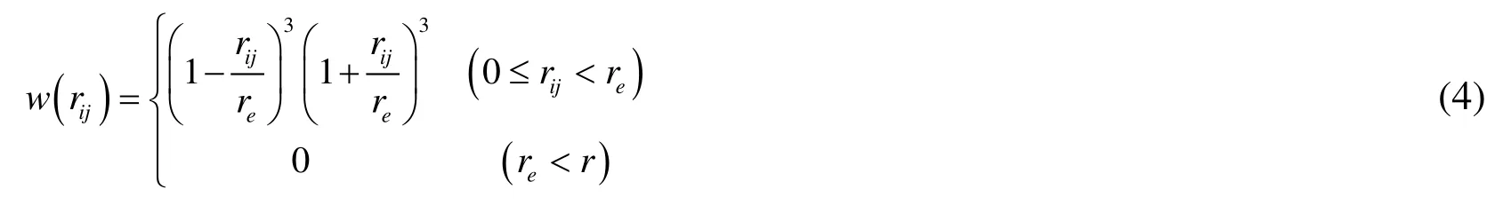
where subscriptionrijdenotes (rj−ri),riis the position of central particlei, andreis the effective range. In this study,reis set to 2.1×l0, wherel0is the initial particle distance[Lee, Park, Kim et al. (2011)]). According to Eq. (4), by definition when the distance between the center particle and its neighbors exceeds its effective range, the neighboring particles have no influence on the central one because the magnitude of the kernel function is reduced to zero.
Another special way of treating particles is by particle number density. The summation of kernel functions within an effective range can be regarded as fluid density. The combination of the kernel function and the concept of particle number density allows the MPS system to be treated as a continuum. The particle number density can be expressed by:


One of the issues in using the Lagragian MPS approach is the estimation of force when particles collide. As particles get close, the overlapping range of each particle can introduce numerical errors. Therefore, a proper collision model is used to adjust the repulsive force and to avoid a sudden increase in particle number density.
When the particles are initially arranged, they are uniformly distant. As they move with a velocity, the distance between them can change and a collision model is activated once their distance goes below a threshold value ofa×l0whereais a constant. After applying the conservation of momentum, the repulsive velocity can be estimated using restitution coefficientb. The parametersaandbcan be assigned using numerical tests, and in this study they are set at 0.97 and 0.2, respectively.
The third-term of the right-hand-side of Eq. (3) denotes the frictional force on a central particle. The frictional force can be measured using the normal force and frictional coefficient. One of the normal force elements is inertial force due to acceleration. For that,it is necessary to calculate the relative acceleration between center and neighboring particles in the normal direction. Then, the corresponding frictional force can be determined as shown in Fig. 1(a). The frictional force due to particle acceleration can be calculated as follows:

wherel0is the initial (or starting) particle distance,µdenotes the frictional coefficient,anis the normal component of acceleration for each particle, anddenotes the unit tangential vector of the frictional force.
An additional component of the frictional force arises from the accumulated weight of particles above the central particle. Since the particles are stacked, the effect of the accumulated weight can be compared to hydrostatic pressure, and should be considered.As shown in Fig. 1(b), particles above a central particle are accounted for in the calculation of accumulated weight. To avoid overestimation, a term for the specific range,orx-interval, is introduced. When the neighboring particles above a central particle are out of thex-interval range, it is excluded from the accumulated effects. The accumulated weight can be calculated as follows:

whereph,iis the accumulated weight of stacked particles,ps,ijis the static weight averaged from the accumulated weight acting on a central particle from its neighbors,rfis the effective range of the central particle in the frictional force calculation,xandzis the particle’s position onx- andz-axes, respectively. In order to avoid overestimation of the stacked effects, therfis set to 0.65, which can be adjusted as needed. With a calculated accumulated weight, the frictional force due to static weight can be obtained from:

where θijis given in Fig. 1.
By combining Eqs. (7) and (10) the total frictional force on a central particle can be calculated as follows:

Frictional force resists forward movement and can only reduce or stop particle motion.Particle motion begins when the inertial or gravitational forces exceed the force of friction. In this case, static coefficients of friction are used. Once particles move, dynamic friction coefficients may be smaller than static ones. However, for simplicity in this paper,the differences between static and dynamic frictional coefficients are assumed to be minimal, and are disregarded.

Figure 1: (a) Schematic of contact model and (b) Accumulated weight on a central particle
3 Applications and numerical examples
The MPS method developed here is next applied in three separate scenarios. The brokendam, cargo-dump, and lamination by gravity sorting. In each application, the method lends insights into the physical behavior of particles.
Generally, a liquid will readily spill out onto a surface due to the absence of significant frictional forces acting between particles. This is not the case for solid particles. Because of this, stacked solid particles tend to assume various forms such as that of a mountain,dune, etc. The angle of repose for the stacked particles will have a range depending on the particle’s properties. In geoscience applications, the coefficient of friction between particles is regarded as foremost among these properties [Clover (1995)].
The following “dam break” scenario compares the behavior of water with that of solid particles (Fig. 2). The container is 0.6 m high, 0.6 m long, lacks a lid, and the rectangular volume is restrained on the right-hand side by a an infinitely thin gate. The materials,whether water or solid particles, have a height of 0.3 m and length of 0.15 m. When the gate is opened at infinite speed, the force of gravity acts on the material. Fig. 3 depicts snapshots taken at various times measured in seconds following the release of the contents. In the first case, the column of water collapses rapidly and collides forcefully against the far wall. The momentum of the moving water generates an upward-directed jet that shoots up the wall. Water behavior simulated in this case (Fig. 3a) was validated against experimental, and other CFD results in authors’ previous papers e.g. Lee et al.[Lee, Park, Kim et al. (2011)], Bakti et al. [Bakti, Kim, Kim et al. (2016)]. The fastmoving water took less than 0.4 s to traverse the tank and slam against the far wall.Eventually the water surface settled to a planar surface parallel to the bottom of the tank.Solid particles under the hindered influence of friction behave quite differently (Fig. 3b),given the same starting conditions. When the barrier is removed, the grains roll down and pile up against one another to form a slope under the influence of friction forces. The development and movement of the free-surface are much slower compared to the water case. The final dune-shape is reached only after the gravitational force acting on each particle no longer exceeds the frictional force. The dune-face is characterized by an angle of repose, which is not quite planar but steepened upward.
The “dam break” simulation above (shown in Fig. 2) is a classical problem for the particle-based Lagrangian CFD solution. The total number of particles used is 4,300 and 1,800 for fluid and solid particles, while others are used for the wall components. The properties of fluid and solid particles are given in Tab. 1.

Table 1: Properties of fluid and solid particles

Figure 2: Numerical setting of broken-dam problem
The “dam-break” example shows that both simulations for water and fine solid grain reasonably correspond to the expectation from physics and typical observation in nature.Next, let us move on to “dumping” problem.

Figure 3: Snapshots of dam-break simulations by MPS comparing the behaviors of fluid and solid particles
The dumping problem shown in Fig. 4 gives a second comparison of fluid and solidparticle behavior. In this simulation, the bottom of a container suspended 17 cm above the floor of a rectangular tank is opened suddenly and its contents spilled out under the force of gravity. For this simulation, 2,938 particles were used for the dumped material and 3,652 particles were used for wall and dummy particles. Water properties and solidparticle properties are the same as those used in the previous example. The total time of the simulation was 5 s and calculations were performed at 0.001 s interval.
Results from the dumping-problem are summarized in Fig. 5. In the case of water, exit from the container is rapid and the vertical momentum upon striking the floor of the tank is converted into horizontal flow in both directions. Backwash from waters colliding with tank walls generates overturning breakers that eventually lose momentum and settle to an equilibrium state. In contrast, solid particles dropped from the same simulated apparatus do not travel far from their first point of impact due to the force of friction. Subsequent particles falling on the loose pile possess diminished kinetic energy as the simulation progresses due to the growing height of the pile and reduction in fall distance. Yet this diminished kinetic energy is offset in part by the enhanced ability of particles to roll, slide and bounce down the pile flanks as the stack slope increases. In the end, the particle stack resembles a dune of uniform slope. Equilibrium is reached once the dune height reaches the mouth of the opening.Runs were made using particles of various coefficients of friction, as seen in Fig. 5. Note how the angle of repose is dependent on the coefficient of friction. At lower coefficients such as 0.1, the dumped material spreads more widely, allowing for the chamber to empty all its contents without clogging. The relationship can be stated as follows:

Figure 4: Schematic view for cargo dump problem


Figure 5: Snapshots of cargo-dump simulation by MPS for fluid and solid particles

Figure 6a: Angle of repose for (a) broken dam and (b) cargo dump problems for identical density and frictional coefficient=0.2

Figure 6b: Angle of repose for cargo dumping with various frictional coefficients
A second dumping simulation was performed in which the height from the containermouth to the tank floor was doubled, to 0.34 m. When Fig.7 is compared with Fig. 5, the result in the case of the raised container corresponds to a stack that no longer reached the height of the release point; yet a small portion of grains of sufficiently high coefficient of friction remained inside the container. Again, the higher frictional coefficients result in steeper angles of repose, like in the previous case. Notice also, that at the lowest frictional coefficient of 0.1, the cusp of the stack is more rounded and the stack more spread out due to the higher kinetic energy of the falling particles. Fig. 8a compares the two stack shapes.
Again, the “dumping” example shows that both simulations for water and fine solid grain reasonably correspond to the expectation from physics and typical observation in nature although the current MPS method does not model all the details of micro-scale particle shapes, sizes, and properties.

Figure 7: Results of solid particle drop from increased height 0.34 m with various frictional coefficients
4 Verification by comparison with DEM
For further verification of the developed MPS-based method, another numerical simulation by a widely used DEM-based computer program was carried out under the same conditions of the dumping problem. In Zhou et al. [Zhou, Xu, Yu et al. (2002)] and Chen et al. [Chen, Liu, Zhao et al. (2015)], their DEM simulations were compared with their experiments and they concluded that the DEM simulation methods can reasonably reproduce the experimental results and thus are adequate in producing the relevant physics. So, in order to validate the developed methodology, we compare the sample case of the present MPS simulation with the DEM simulation using the same sets of parameters.
For the DEM simulation, the open-source software, LIGGGHTS-PUBLIC was used.According to this program, the particle’s motions are updated in time domain by calculating momentum equations including inertia and interaction forces with neighboring particles or walls, which is very similar to the present case. The damped Hertzian contact model was employed to estimate interaction forces between particles which can be described by the following equation:


Table 2: Parameters used for DEM simulations (same as Fig. 8a although Yong’s modulus, Poison ratio, and Roll-friction coefficient not used in the present MPS method)

Figure 8a: Comparison of final stack shape from particles dropped from heights of 0.17 m and 0.34 m, for 0.1 coefficient of friction

Figure 8b: Comparison of final stack shape from particles dropped from heights of 0.17 m and 0.34 m with friction coefficient=0.1 by DEM simulations (same as Fig. 8a)
The MPS and DEM methods show similar trends having wider spread with lower and more rounded top for higher container location due to more kinetic energy of the dropped particles.For both cases, their stack heights are very similar too. In case of lower dump, their slopes are almost constant and the angles of repose are 22.5oby DEM and 22.3oby MPS. In case of higher dump, both cases show curved slopes with varying angles. They generally agree well except the minor thin tails at both ends of DEM. DEM can model the shapes and physical parameters of individual particles while SPM only uses the representative averaged values at respective collocation points. When the individual modeling of DEM is used for very fine particles, the CPU time will greatly be increased compared to SPM. When fine particles move with ambient fluid motions, the present MPS can straightforwardly model the solidfluid combined case while DEM can hardly be employed for this kind of application.
5 Segregated-lamination simulation by multi-particle MPS
The phenomenon of segregated lamination by gravity sorting is next simulated using the same MPS method, with the added complication of a heterogeneous mixture of particles.Previous simulations used only homogenous particles. Interesting experiments of segregated lamination using mixed heterogenous sands dropped in air from a container were reported in Julien et al. [Julien, Lan, Berthault et al. (1993, 1994)]. Fig. 9 is a photo of results from one of these lab experiments using sands that were bimodal in density distribution. Julien et al.[Julien, Lan, Berthault et al. (1993, 1994)] reported clearer lamination when using a mix of two sands that differed in both density and grain diameter. Bouncing and rolling distances of the two grain populations were not the same, resulting in well-defined lamination, which improves with greater rolling distances. The gravity sorting of heterogeneous grains into laminae has also been documented in a water flow in a laboratory water flume. This finding could have important implications for understanding sediment behavior, including the rapid accumulation of vertically stacked laminae under flood-conditions.

Figure 9: Experimental lamination of a heterogeneous mixture of two sands that differ in density and grain-diameter
In this regard, the solid MPS method is next applied to investigate segregated lamination in air, using the same numerical apparatus as those from previous “cargo dump” runs.Three particle populations, each different in density yet identical in size, were selected.Initially, three different particles are arranged by 6 layers. When the contained moth is suddenly opened, the three particles are mixed and fall simultaneously as a heterogeneous mixture. The mixed particles fall and accumulate as a stack, gravity sorting (segregated lamination) of grains takes place spontaneously. The simulated results strongly resembled Julien et al.’s [Julien, Lan, Berthault et al. (1994)] lab results. Fig. 10 shows starting conditions for the simulation of three populations of particles arranged in six layers. The particles differ in density and frictional coefficient as listed in Tab. 3 but are identical in size. Fig. 11 depicts two snapshots in the progress of the run, and Fig. 12 shows the two snapshots for sorted individual grain population. In Fig. 12 for 5 s snapshot, we can clearly see that all 3 particles are falling simultaneously as a heterogeneous mixture. If it were three specific liquids with the three different densities, the eventual separation by 3 layers is caused by buoyancy forces. Solid particles behave much differently in this respect, that they sort into a continuous series of discrete, density specific laminae.

Figure 10: Initial arrangement of multiple solid particles for a MPS simulation of gravity-sorted-lamination

Figure 11: Results of a solid particle drop with grains of multiple densities


Table 3: Properties of the dropped object
Fig. 13 shows a repeat of the run shown in Fig. 11 with the change in frictional coefficients. Particle densities remained the same and the new frictional coefficients are applied uniformly to all particles. This resulted in a new shape for the stacked particles,but the tendency to segregate into laminae remains true regardless of the change in frictional coefficients. Clearly, density difference plays a far greater role than friction in the phenomenon of gravity sorting.

Figure 13: Snapshots of multiple solid particle drop: Left=all friction coefficients 0.2;Right=all friction coefficients 0.4 at 15 s
Finally, starting from the same initial arrangement of Fig. 10 with the same density combination of fluids as the solid-particle case, the behaviors of low-viscosity and highviscosity heterogeneous fluids are simulated and compared against the solid-particle cases. The properties of the constituent fluid particles are listed in Tab. 4. Fig. 14 shows the results. In the case of fluids, viscosity functions in a way that is comparable to the role that friction plays in solid particles. Even highly viscous fluids like muds do not result in sloped surfaces characterized by an angle of repose, as solid particles do.Instead they segregate via buoyancy forces into respective layers, with flat and horizontal bounding surfaces. Low viscosity liquids reach equilibrium more quickly than highviscosity ones, but both result in horizontal and flat bounding surfaces.

Table 4: Characteristics of dropping objects (three liquids model)

Figure 14: Results of multiple liquid particle drop
6 Concluding remarks
A new Moving Particle Semi-implicit method has been developed by the authors to simulate the behavior and interaction of multiple solid particles as a continuum. Compared to fluids, solid particles are affected by frictional forces rather than by viscosity. The new method represents a modification of existing MPS equations for application in solid particle problems and successfully simulates particle behavior in the broken-dam and cargo-dump types of problems. The present MPS results for dumping solid particles were validated against the corresponding DEM results, which were previously verified against experiments.The developed MPS method also reproduces via simulation the peculiar behavior of lamination-by-density-sorting from a heterogeneous mixture, a little-understood and yet experimentally-proven real phenomenon. Sedimentologists involved in numerical modeling can benefit from the new model, which can potentially determine upper limits for rates at which laminated sediments can accumulate, for example during large-scale flood situations.By combining with fluid MPS method, the developed program can also be applied to tsunami generation by land-slides.
Acknowledgement:This research was supported by Basic Science Research Program through the National Research Foundation of Korea (NRF) funded by the Ministry of Education (NRF-2018R1D1A1B07048254) and Tongmyong University Research Grants 2018(2018F030).
杂志排行

Computer Modeling In Engineering&Sciences的其它文章
- Investigation on Purine Corrosion Inhibitions via Quantum Chemical Calculation
- Mass Transfer of MHD Nanofluid in Presence of Chemical Reaction on A Permeable Rotating Disk with Convective Boundaries, Using Buongiorno’s Model
- An Explicit-Implicit Mixed Staggered Asynchronous Step Integration Algorithm in Structural Dynamics
- Distance Control Algorithm for Automobile Automatic Obstacle Avoidance and Cruise System
- Optimal Model of Continuous Knowledge Transfer in the Big Data Environment