Study on the Configuration Properties of the Surface Dielectric Barrier Discharge Actuator
2018-07-20JiangsuElectricPowerCompanyNanjing0000ChinaSchoolofControlScienceandEngineeringShandongUniversityJinan50000China
, , , (.Jiangsu Electric Power Company,Nanjing 0000,China;.School of Control Science and Engineering Shandong University,Jinan 50000,China)
Abstract:The actuator of the surface dielectric barrier discharge(SDBD)plays an important key in generating plasma. The aim of this study is to investigate the effect of the configuration of the plasma actuator on the discharge excited by a sine wave power at atmospheric pressure experimentally and numerically. It is found that under the same conditions,the symmetric configuration actuator has the maximum static electric field intensity,the largest plasma layer area,the highest brightness,and the biggest power consumption. The plasma produced by the asymmetric configuration actuator symmetrically distributes at the upper and lower electrodes,with the lowest brightness and the overall look was uniform,but the static electric field intensity of this configuration is minimum. The static electric field intensity in the vicinity of the upper electrode increases in the case of the asymmetric configuration actuator with an encapsulated lower grounded electrode. Plasma distributes only in one side of the upper electrode,with the smallest plasma and the worst uniformity. It is verified that the encapsulated SDBD restrains discharge at the lower grounded electrode resulting in the lowest power dissipated.
Key words:SDBD;plasma actuator;electrical experiment;high speed image;comsol
The surface dielectric barrier discharge(SDBD)plasma is an important flow control method used to improve aerodynamic characteristics for their special features,including their simplicity,robustness,low-power consumption,and fast response time[1-5]. The plasma actuator,as an energy transfer medium,has received significant attention from the flow control community in recent years. Many authors reported characteristics of the SDBD plasma including its electrical parameter,energy consumption,optical properties and many others[6-10]. Takashima et al. studied the influencing factors,including voltage peaks,electrode length,and repetition frequency,on discharge mode[11]. Che et al. studied the effect of exposed electrode and implant electrode width and the distance between the two electrodes on discharge characteristics[12]. It is shown that the parametric variations of the applied voltage amplitude,frequency,dielectric material,geometry of the actuator(electrode size,thickness,electrode gap,etc.)had an important impact on the actuator performance.
Additional information about characteristics of plasma parameters in the discharge can be obtained by means of numerical modeling. HJM Blennow,et al. established a simple model to calculate the space charge distribution in the gas of a dielectric barrier discharge[13]. YV Serdyuk,et al. calculated the continuity equations coupled with the Poisson equation to acquire the distribution of charged particles and excited particles in the gas discharge[14]. Li Yinghong,et al created symmetrical plasma actuator model for simulation using PSpice[15]. Cheng Yufeng,et al investigated the plasma aerodynamic actuation process in near space by numerical analysis[16]. Soloviev and Zhu et al present the results of calculations for SDBD in plane-to-plane geometry at atmospheric pressure[17-18]. In the majority of these modeling approaches the final goal is to determine the essential of the discharge for further applications.
Though a large number of papers focused on configurations of the actuator,there have no articles introducing them systematically. Typically,the SDBD actuator is composed of two plane electrodes flush-mounted on both sides of a dielectric plate. One electrode is excited by an AC high voltage(usually a sine waveform)and the other one is grounded. In this paper,the influence of configuration on the discharge characteristics are discussed including a symmetrical configuration with a large sheet lower grounded electrode,an asymmetric configuration,both upper electrode and the lower electrode are banded,and the configuration working with an encapsulated lower electrode based on the asymmetric configuration. Furthermore,the discharge happens rapidly and complexly,which could not be fully experimentally measured for the limitations of the diagnostic tool,so the numerical method is particularly important.
In this paper,we focus on the details of the effect of the three actuators configurations on the discharge by the experimental and numerical method. Voltage and current waveforms,discharge image,power consumption,and static electric field distribution will be analyzed. It will be important to improve the efficiency of the plasma actuator,optimize plasma actuator design,and expand its scope of application,and even provide a reference for multi-electrode plasma actuator.
1 Experimental Setup
The experiments are carried out at the silent air and normal indoor temperature. The configuration of the SDBD actuator with asymmetric configuration is shown in Fig.1. It consists of two metal electrodes formed on both sides of a dielectric plate,which is a Al2O3sheet. Each electrode has a length of 165 mm and a thickness of 50 μm. The upper discharge electrode with spikes spaced at 6 mm intervals has a width of 0.1 mm.
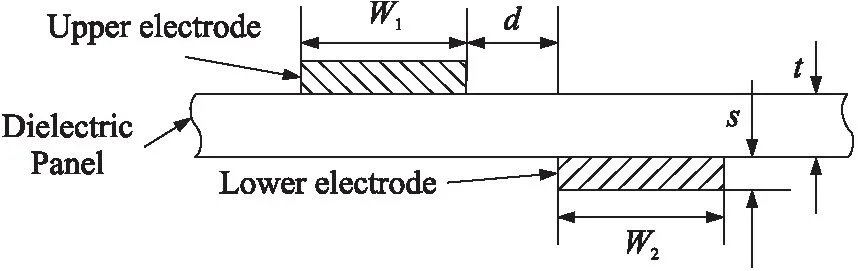
Fig.1 Cross-view of SDBD
The lettersw1,w2,d,sandtstands for width of the upper electrode,width of the lower electrode,air gap between the electrodes,thickness of the electrodes and thickness of the dielectric respectively. In the experiment upper electrode is connected to the power sources and the lower one is connected to the ground. The main parameters are shown in Table 1.
Table1SDBDactuatorparameters
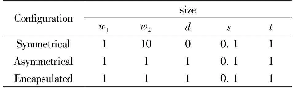
Unit:mm
Fig.2 shows the experimental equipment of SDBD. AC power supply is connected to the plasma power source through booster. The booster can be ranged between 0 and 220 V. The ammeter and voltmeter are used to measure forward current and voltage. The plasma power source(CTP-2000K)can be set 0~30 kV and 3 kHz~30 kHz.C1andC2are dividing capacitor withC1=47 pF andC2=47 pF,and the ratio is 1 000. The measurement capacitor isCM(CM=0.47 μF)and measurement resistance isr(r=50 Ω). The dielectric uses Al2O3. Voltage and current signals are recorded by the digital oscilloscope Tektronix 4014B(1 GHz,5 GS/s). At the same time a high-speed camera(Hispec5)is applied to characterize the time-resolved discharge image of the plasma actuator.
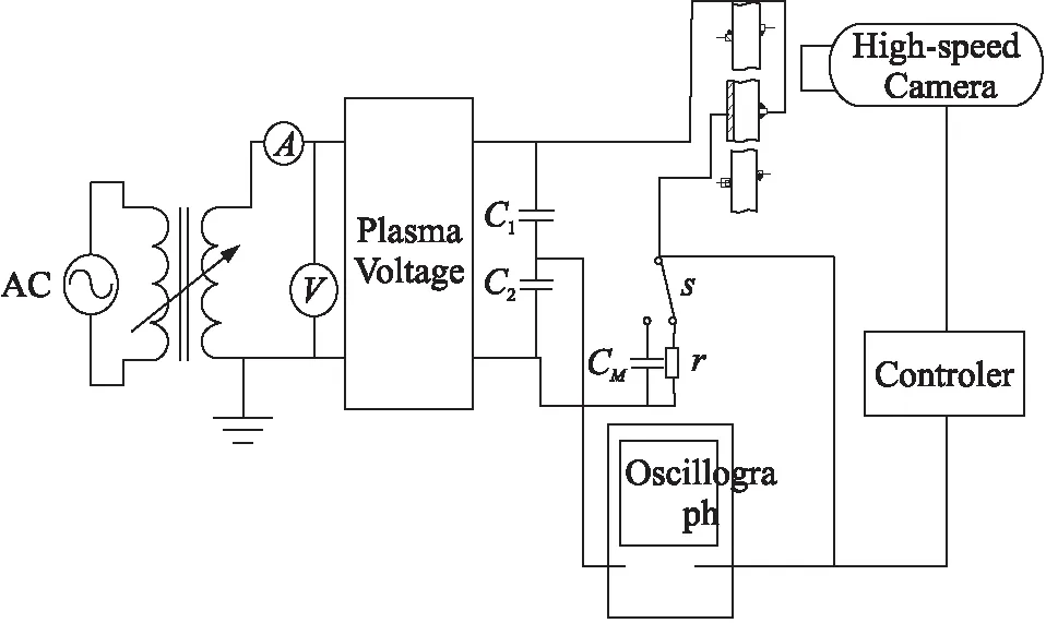
Fig.2 Experimental equipment of SDBD
2 Numerical Simulation
The numerical study in this work is performed entirely in the framework of the plasma module of comsol software. Different SDBD actuator configurations are simulated using a simple 2D electrostatic model to simulate the discharge in the experimental set-up. By solving the Poisson equation(1)to get the distribution of the static electric field.
·(ε0εrE)=ρV
(1)
WhereVis the space potential andρVis the space charge density,which is automatically computed based on the plasma chemistry specified in the model using the formula:
(2)
WhereZiis the positive ion charge number,andniis positive ion density.
The geometric model of the three actuators are is identical with the experimental model. Under the environmental conditions(Tg=300 K,P=105Pa),the value of the relative permittivity of the dielectricεr=10,and the encapsulating dielectric is kapton withεr=3,while the relative permittivity of gas is 1. The upper electrode is connected to a high voltage(U=5 kV),while the lower electrode is grounded.
3 Results and Discussion
3.1 Current Characteristics
Fig.3 shows the discharge current and voltage waveforms atUpp=10 kV,f=9 kHz. The voltage is approximately sine wave while the current is many pulse signals attached to sine wave. The current waveforms of the three configurations are mainly composed of the capacitive current and the discharge current. Capacitive current is due to the capacitive effect between both electrodes,which consists of a sine form in phase quadrature compared with the voltage signal,and which does not correspond to any discharge phenomenon. A series of pulses with a width of a few microseconds,appearing when the voltage polarity is about to reverse and collapsing shortly after the voltage has reached its maximum absolute value. These pulse series are the discharge current,which indicates that the mode of the discharge is filamentary regime.
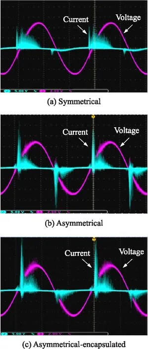
f=9 kHz,Upp=10 kVFig.3 Voltage and current of the three actuators
According to Fig.3(a),(b),(c),during a voltage cycle,it can be observed that the series of pulses appear mainly during the positive half-cycle,whereas only a few peaks of similar intensity are observed during the negative voltage half-cycle in the symmetrical actuator. Compared with other configurations,the most intensive current pulses and the highest average current amplitude can be found. Asymmetric configuration of the discharge occurs in both positive and negative half cycles,with a stable peak current at each half-cycle,but the average current amplitude is the lowest. When it works with the asymmetric encapsulated,the number of current pulses is slightly reduced,and the amplitude increases,though the magnitude is still less than the case of a symmetrical configuration. It is similar to symmetrical actuator that discharge mainly occurs in the positive half cycle,which proves that plasma near the lower electrode is generated at the negative half-cycle of the voltage and can be evidently inhibited by these two configurations.
3.2 High-speed discharge image
Fig.4 shows the photos of the SDBD taken by the high-speed camera at different applied peak-to-peak voltages(10,11,12,and 13 kV)and at a fixed frequency of 9 kHz.
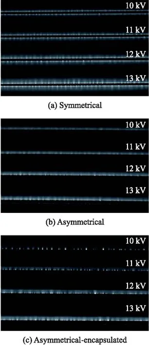
Fig.4 High-speed image of the three actuators
It is shown that the discharge mode of the surface dielectric barrier discharge is filamentary. When the voltage is low,the discharge filaments are sparsely distributed like clusters with larger diameter. Increasing the voltage value may reduce the diameter of the cluster and increase plasma area. Then,as the voltage grows,discharge becomes more brightly,meanwhile,the appearance of the plasma seems more intensive and uniform. One possible explanation is that at a certain frequency,if the voltage value is low,few filaments will appear randomly. Once the discharge filaments are formed,it is more prone to discharge here,and gradually forms a discharge cluster. According to the increase of the voltage,electric field intensity becomes larger,more and more discharge filaments emerge and spread out,so the discharge seems more uniformly. In addition,we noticed that there exist an intrinsic relationship between distribution of the discharge filaments and current pulse from voltage and current wave forms. The more the number of current pulses is,the more dense and more uniform discharge filaments appear,and vice versa.
According to Fig.4(a),the symmetry actuator discharge is the brightest,with the most discharge filaments per unit length,the largest plasma area and the densest distribution. When the voltage is lower,the plasma generated by the asymmetric actuator looks more uniform. More filamentous discharge will appear as the voltage increases(see Fig.4(b)). In the case of the asymmetric encapsulated actuator(see Fig.4(c)),the plasma brightness is among the three configurations,and the diameter of the discharge cluster is the largest,especially,certain discharge clusters being quite bright. But unfortunately the smallest plasma area and the worst uniformity appear.
3.3 Power consumption
In order to compare the electrical characteristics of the plasma actuator in different configurations,the discharge power is measured since it can be a key parameter to assess the actuator efficiency.The discharge power is calculated by the method ofQ-VLissajous. The channel 1 of oscillograph is connected to divider and channel 2 to CM. The Lissajous figure is showed in Fig.5. The applied voltageUpp=10 kV andf=9 kHz. In the figure,A-DandB-Crefer to discharge section whileA-BandC-Drefer to extinguish section. The discharge power can be calculated by equation(3).
=fCM∮UdUM=fCMA
(3)
In the equation(3),fis power resource frequency andArepresents the area of Lissajous figure.
Results are presented in Fig.6 for three different configurations. It is obviously that symmetrical actuator consumes the maximum power,followed by the asymmetric configuration,while the power consumption of the asymmetric configuration encapsulated is significantly minimum. It shows that the encapsulated SDBD consumes approximately half power of the asymmetric configuration. The conclusion is in consistent with voltage current image and discharge image. In other words,the power consumption is in direct proportion to the current density,luminous intensity and area of the plasma. Encapsulation of lower electrode suppresses the generation of the plasma,so the power consumption is significantly reduced.
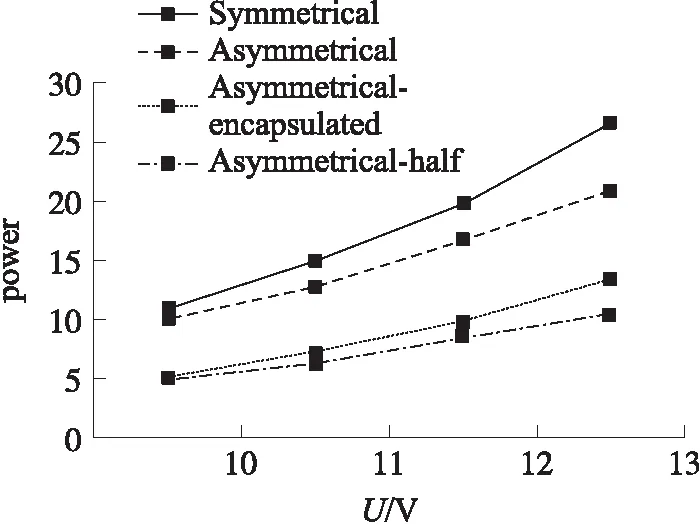
Fig.6 Power consumption the three actuators
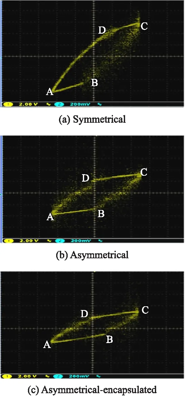
f=9 kHz,Upp=10 kVFig.5 Lissajous of the three actuators
3.4 Static electric field distribution
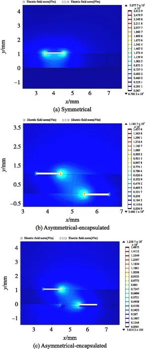
Fig.7 Distribution of the static electric field of the three actuators
Fig.7 shows the distribution of the static electric field of the three configures using the comsol. The electric field symmetrically distributes at both sides of the upper electrode of symmetrical actuator(see Fig.7(a)),and the maximum electric field strengthEis 2.07×10⁷V/m which is found at the edge of the electrode,while the field strength of the lower electrode is already close to 0. Fig.7(b)describes the case of the asymmetric actuator,where the electric field symmetrically distributes at both sides of the electrodes,but the maximum value of electric field strength is reduced to 1.14×10⁷V/m. Compared with the symmetrical actuator,after lower electrode encapsulated,the electric field at the upper electrode is enhanced and the maximumEis up to 1.25×10⁷V/m,while the strength of the lower electrode is decreased,and even zero at the edge of the encapsulation dielectric(see Fig.7(c)).
It can be explained that:electric field intensity is the essential factor for the discharge,which is related to the charge. Accumulation of the charge in the electrode is proportional to the capacitanceC(C=ε0εrS/d). Hence,the greater the plate area is,the more the charge accumulates. The area of lower electrode of the symmetrical actuator is large,therefore,the electric field intensity enhances due to more charges accumulating in the electrode. Furthermore,the largest electric field intensity is found at the upper electrode of the asymmetrical-encapsulated actuator,which is larger than that of the asymmetrical actuator. That can be attributed to the relative permittivity near the electrode increasing. However,the electric field intensity reduces at the lower electrode and the discharge is suppressed. As a conclusion,the greater the electric field intensity is,the more easily the discharge occurs,and there will be more intensive current pulses,higher amplitude of the current,larger plasma area and higher luminance.
4 Conclusion
In this paper,the effects of different actuator configurations are considered in order to obtain the best outcome of the discharge. Voltage and current waveforms,high-speed discharge image and power consumption have been attained using an experimental technique. The static electric field distributions are implemented in a numerical method based on comsol. The main conclusions are as follows:
①The symmetric configuration actuator in which plasma generated at both sides of the upper electrode,had the maximum electric field intensity,the largest plasma layer area,the highest brightness,and the biggest power consumption.
②The plasma produced by the asymmetric configuration actuator symmetrically distributed at the upper and lower electrodes,and the lowest brightness and the overall look is uniform,but the electric field intensity of this configuration is minimum.
③The electric field intensity in the vicinity of the upper electrode increases in the case of the asymmetric configuration actuator with an encapsulated lower grounded electrode. Plasma is distributed only in one side of the upper electrode,with the smallest plasma layer and the worst uniformity.
It is demonstrated that the encapsulated SDBD restrains discharge at the grounded electrode resulting in the lowest power dissipated