低能粒子束技术中尺寸效应的分子动力学研究
2018-01-29桑胜波李廷鱼
魏 也, 周 兵, 桑胜波, 邓 宵, 柴 晶, 李廷鱼,
李 刚1, 陈泽华1,4, 张文栋1
(1. 太原理工大学 信息工程学院, 山西 太原 030024; 2. 太原理工大学 表面工程研究所, 山西 太原 030024; 3. 太原理工大学 物理与光电工程学院, 山西 太原 030024; 4. 太原理工大学 大数据学院,山西 太原 030024)
粒子束技术是表面修饰、 薄膜生长和微纳器件加工的重要技术[1-7]. 粒子束技术日新月异, 这类技术的共同特点是通过加速后获得能量的团簇粒子在靶材料上刻蚀和沉积, 从而实现薄膜生长[5-7]、 原子替换[8]、 粒子注入[9,10]和器件加工[11,12]. 粒子注入后所形成的界面深度特征直接影响后续制造中的电气连接、 光学特性和机械性能[13-15], 可以通过优化加工工艺改善器件性能. 较新的离子束注入技术可以控制生成注入粒子的初始粒径(在80 nm以下)[16]及其粒径分布特性[17], 从而定量实现纳米级表面改性.
实验过程中调整注入离子能量可实现精确控制掺杂替代的位置和深度[18]. 数值模拟作为研究微观成型机理的重要方法, 被广泛深入研究[19]. 其中分子动力学方法由于其高效的计算方式可用于优化工艺参数、 评价器件性能和解决复杂问题[20-31], 如分析谐振器频率特性[21,22]、 表面特性等[23,24]以及对注入能量、 角度、 元素类型、 温度和基底材料晶向的深入研究[25-30]. 黄海等研究了铜-石墨烯体系中粒子的扩散和纳米复合材料形成的纳观机制[28]. 但现阶段大部分模拟研究集中在溅射或沉积, 而粒子注入过程的原子行为、 注入深度的生成机理和过程因素对于相关特性的影响仍不明确. 为了更有效控制注入过程用以预测界面特性进而评估纳米器件性能, 需要对粒子注入技术中的尺度效应及其机理进行深入研究.
本文以铜粒子注入单晶硅形成表面结构为例, 使用分子动力学方系统比较分析了团簇粒子的注入、 反射、 扩散和最终注入基底的全部运动过程, 同时使用可视化方法观测记录基底表面形貌演化过程, 引入并计算注入率来定量比较注入过程的不同. 通过研究注入粒子尺寸(数量)、 初始注入能量和角度变化对注入过程的影响揭示了注入技术机理, 直观地显示了低注入能量域内的新特征. 同时, 给出了模拟过程的计算方法和详细参数设置, 仿真结果表明所提出方法可用于定量预测注入粒子的表面分布特性. 本研究可作为纳米尺度下生成基底表面特征或设计图案的参考, 并对可控表面注入技术提供理论指导.
1 粒子注入模型
本文研究的粒子注入过程可以等效为不同数量原子及离子的团簇粒子轰击过程. 理想情况下考虑单次轰击过程以简化该模型[29-31], 注入模型示意图如图 1 所示.
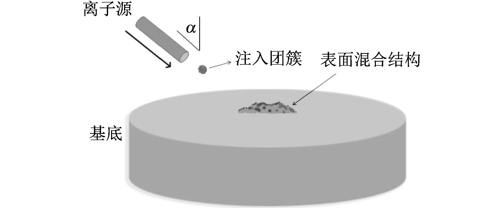
图 1 铜粒子束注入单晶硅工作原理示意图Fig.1 Schematic of copper cluster implantation on crystalline silicon
离子源产生的离子束以一定能量和角度α入射到单晶硅中. 其中注入团簇由不同数量的铜原子组成, 与基底硅原子发生物理反应后, 在表面形成具有特殊形貌的改性层.
2 数值模拟方法
2.1 计算原理
描述团簇粒子注入过程的经典运动方程为
(1)
式中:mi,ri,vi和Fi分别表示团簇粒子中第i个原子的质量、 位移、 速度和力. 除质量mi外, 其余变量均为在时间步长dt内计算的三维向量. 描述该物理原子间反应的势能(r1,r2,…,rNatoms)是包含该系统范围内所有原子的位移函数. 本文工作势能选择类型为: Cu 原子之间作用为嵌入原子势能(EAM)[32], Si 原子之间作用为Stillinger-Weber 势能[33], Cu 和Si原子之间势能选取为已验证可以有效模拟该体系的Morse势能[34-36]. 所采取的数值方法在对应时间尺度上自适应调整原子数目、 温度和压力信息. 第3节将描述及讨论时变团簇运动的纳米尺度观测图. 详细的模拟设置及对应参数在2.2节给出.
2.2 数值模拟方法
粒子注入前位于基底中心位置, 略高于基底表面. 其中团簇由不同原子数目组成, 将在后文工作中详细讨论, 计算中选择注入角度为45°, 且不考虑注入角度对沉积过程的影响. 图 2 分别给出了xoy和xoz平面内铜团簇轰击硅基底表面的粒子注入过程.
注入前初始模型中晶格常数a为5.43 Å,θ为注入角度. 基底共由504 751个硅原子组成, 晶向为(100)面. 基底尺寸大小为28.2 nm×28.2 nm×14.2 nm. 其中基底最外三层原子(3a)固定以确保沉积过程中整个模拟系统的稳定性. 其余内部原子是活动状态. 着色不同表示初始状态属于不同原子层的原子, 以区别注入过程中的轨迹. 模拟使用大规模分子原子并行模拟器实现(LAMMPS)[37].
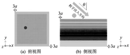
图 2 仿真模拟的系统模型Fig.2 Schematic of implantation process
整个系统(包含粒子和基底)中全部原子驰豫10 ps且在室温达到稳定结构后再开始模拟注入过程. 假设系统工作环境为真空状态同时原子反应为完全弹性碰撞, 选择NVE系综分别自适应调整注入粒子和基底的体积和能量. Berendsen热浴方法[38]应用于基底的活动区域. 在控制温度和系综同时确保底层原子在整个注入过程中保持固定. 时间步长为5 ps, 初始高度小于截断半径以保证模拟过程中反应原子在势能的有效范围内. 使用OVITO软件[39]对全部模拟沉积过程进行可视化处理.
3 模拟结果和分析
记录了表面形貌演化和纳观相变过程, 分别详细比较了粒子注入能量、 角度和粒径大小对注入动力学过程的影响. 详细记录了粒子注入后原子空间分布的演化过程. 为更好区别不同因素影响, 总共进行了45组独立模拟.
3.1 注入粒子数量对表面形貌影响分析
注入过程中, 团簇粒子由不同粒径和数量的硅原子组成. 本组团簇粒子具有相同的注入能量和角度, 注入角度为60°. 图3(a)~(d)是基底中心截面图(平行于Cu55的轰击方向), 最大注入深度为16.5 nm, 弛豫时间大约为17.5 ps; 图 3(e)~(h) 是Cu490注入过程, 最大注入深度为32.5 nm. 弛豫时间大于32.5 ps, 在注入方向上形成了明显的环状突起结构.
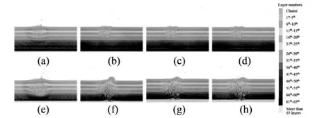
图 3 初始能量为200 eV的Cu55和Cu490以不同采样时间500 fs, 7.5, 17.5, 32.5 ps 的注入过程Fig.3 Snapshots of implantation for Cu55 and Cu490 with 200 eV in 500 fs, 7.5, 17.5, 32.5 ps
3.2 注入粒子能量对表面形貌的影响分析
模拟中同时测试了3组不同注入能量对离子注入过程的影响, 分别统计了200, 300和600 eV的原子注入行为, 其结果如图 4 与表 1~表 3 所示. 图 4(a)~(d) 为600 eV Cu236的注入过程, 最大注入深度为35.3 nm图 4(e)~(h)给出了300 eV Cu236的注入过程, 最大注入深度为32.5 nm, 弛豫时间均约为17.5 ps, 注入角度为80°. 受影响区域大小为32.5 nm×32.5 nm×32.5 nm, 反应界面均未形成明显环状结构. 与图 3 对比, 发现弛豫时间显著减小, 说明注入能量越大, 注入过程越短.

表 2 注入能量为300 eV的注入原子数统计
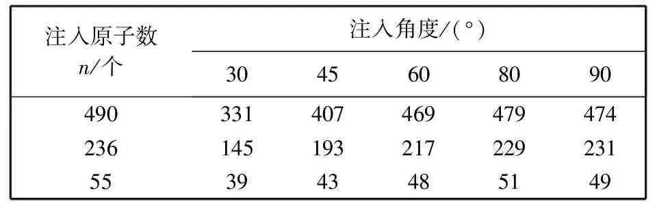
表 3 注入能量为600 eV的注入原子数统计
3.3 注入粒子角度对表面形貌影响分析
注入角度对注入深度有较大影响, 如图 5 所示. 注入角度为30°时, 最大注入深度为19 nm, 弛豫时间约为50 ps, 注入原子数为233, 表面形成不规则环状结构; 注入角度为60° 时, 最大注入深度为32.6 nm, 弛豫时间约为32.5 ps, 最终注入原子数为339.
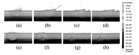
图 5 初始能量为200 eV的Cu370在不同采样时间500 fs, 7.5 ps, 17.5 ps, 32.5 ps下的注入过程Fig.5 Snapshots of implantation for Cu370 with initial energy of 200 eV in 500 fs, 7.5 ps, 17.5 ps, 32.5 ps
本文使用式(2)计算单粒子注入率,Npla表示植入基底原子,Nall表示注入团簇所包含的原子数量. 所有测试样本的注入率μ分别在图 6(a), 7(a), 8(a)中列出.
(2)
3.4 表面特性分析
本文统计全部测试样本的原子注入行为和深度特征用以定量分析注入特性. 图 6~图 8 分别给出了注入特性和初始注入粒子组成原子数N, 角度θ以及注入能量E的具体函数关系.
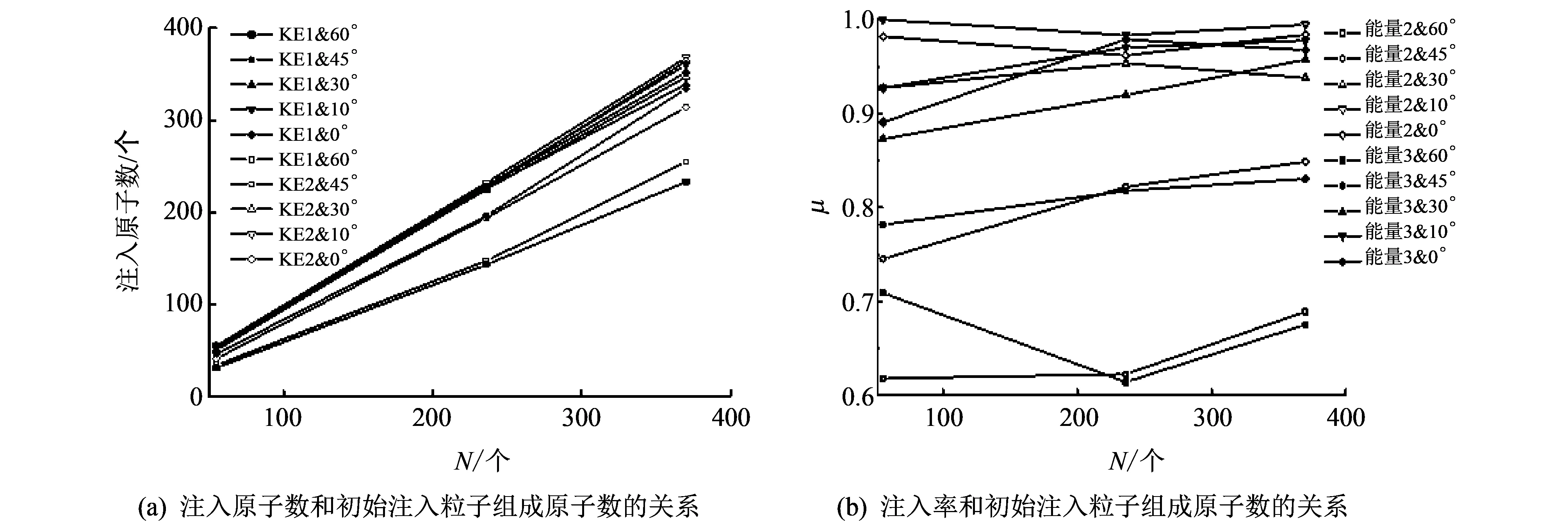
图 6 注入特性和和初始注入粒子组成原子数N的关系Fig.6 Implantation characteristics as a function of composing atom numbers
图 6 和图 7 中, 能量1, 能量2和能量3分别为200, 300和600 eV. 图 6 中注入率和初始注入粒子组成原子数呈正比关系, 比例系数随角度和能量变化而不同. 注入角度越小, 注入原子数越多, 注入率也越高. 注入角度为10°和0°时, 注入率明显增加, 10°的注入率略高于0°. 相比注入角度和粒径, 注入能量对注入原子数量和注入率的影响较小.
图 7 和图 8 中尺寸1, 尺寸2和尺寸3分别表示粒子数为370, 236和55个. 图 7 为沉积角度对注入率的影响. 可见注入角度越大, 注入率越小, 两者呈非线性反比关系. 具有不同能量的相同原子数的团簇注入数量基本相同. 注入率在(0.6,1)范围内变化, 注入率在注入角度超过30°后显著降低. 同时, 使用垂直角度(0°)注入时不能达到最大注入率.
图 8 是初始注入能量对注入率的影响示意图. 可见在所研究能量范围内, 注入能量对植入原子数量和注入率并无显著影响.
基于所建立模型对全过程(植入, 扩散和反射)的尺寸效应做了系统分析. 统计比较了分别具有3种注入能量的3种粒径的团簇以5种角度注入, 共计45个测试样本. 通过可视化方法分析基底表面形貌演化过程, 所测试能量范围内原子尺度的注入行为基本一致, 但随尺寸和能量大小的选择不同而异. 注入能量越小, 粒径和注入角度越大, 驰豫时间显著增长; 植入原子数量与粒径(粒子所组成原子数量)成线性相关. 仿真结果表明所提出方法可用于定量预测注入粒子表面分布. 下一步工作将增加样本数和考虑多次轰击基底过程.
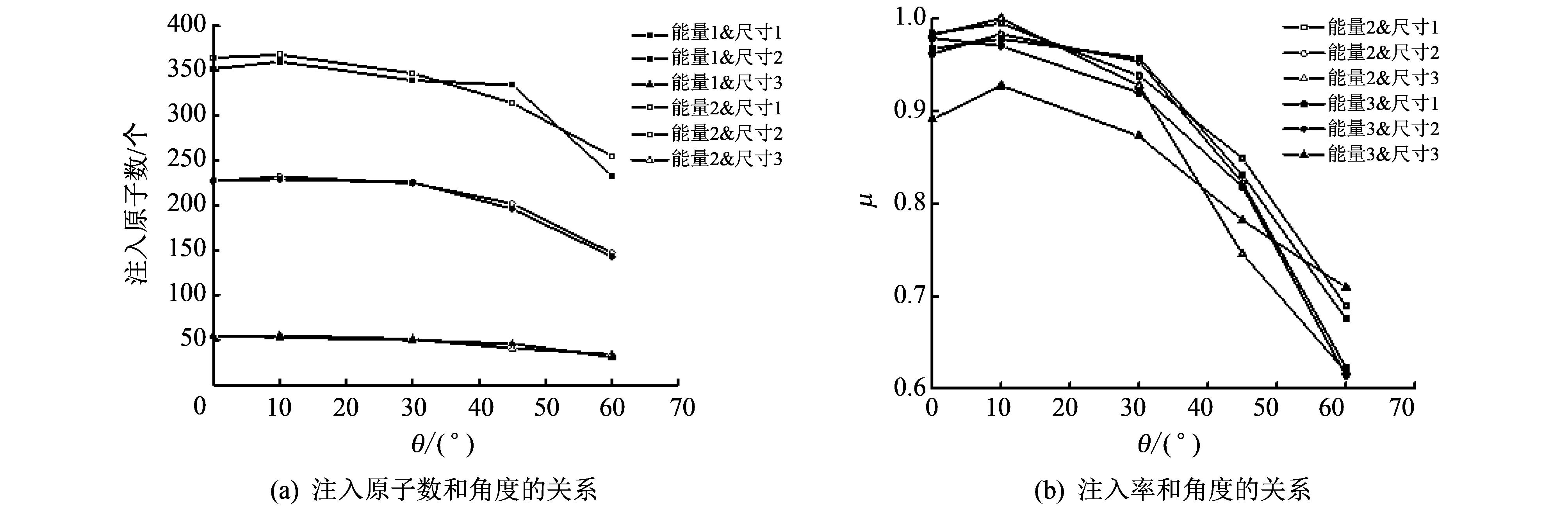
图 7 注入特性和角度θ的关系 Fig.7 Implantation characteristics as a function of incident angle
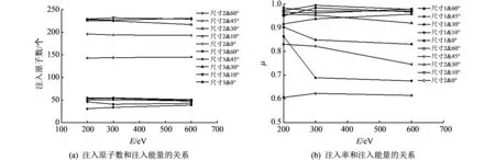
图 8 注入特性和初始注入能量E的关系Fig.8 Implantation characteristics as a function of kinetic energy
4 结 论
本文在纳米尺度和皮秒量级下精确复现了铜粒子注入硅基底的全部动力学过程, 使用可视化分子动力学系统定量研究了观测模拟结果, 比较分析粒子行为后可得: 在所研究低能量域范围内, 注入率与粒子尺寸基本保持正比关系, 其比例系数与初始能量相关, 能量越大, 该比例系数越大. 同时, 注入角度与注入深度呈反比, 初始能量与注入深度呈正比, 注入角度约为10°时得到最大注入率. 仿真结果说明本文方法是对纳米界面新结构测试分析的有效工具. 对于采用粒子注入方法物理实现纳观复杂结构的精确参数优化设计和纳米级加工控制均具实际参考价值.
[1] Abadias G, Tse Y Y, Guérin Ph, et al. Interdependence between stress, preferred orientation, and surface morphology of nanocrystalline TiN thin films deposited by dual ion beam sputtering[J]. Journal of Applied Physics, 2006, 99(11): 113519.
[2] Eda Çetinörgü, Bill Baloukas, Oleg Zabeida, et al. Mechanical and thermoelastic characteristics of optical thin films deposited by dual ion beam sputtering[J]. Applied Optics, 2009, 48(23): 4536-4544.
[3] Eberhard Spiller, Baker S L, Mirkarim P B, et al. High-performance Mo-Si multilayer coatings for extreme-ultraviolet lithography by ion-beam deposition[J]. Applied Optics, 2003, 42(19): 4049-4058.
[4] Rading D, Moellers R, Crame H G, et al. Dual beam depth profiling of polymer materials: Comparison of C60 and Ar cluster ion beams for sputtering[J]. Surface and Interface Analysis, 2013, 45(1): 171-174.
[5] Johansson B O, Hentzell H T G, Harper J M E, et al. Higher nitrides of hafnium, zirconium, and titanium synthesized by dual ion beam deposition[J]. Journal of Materials Research, 1986, 1(3): 442-451.
[6] Cevro M, Carter G. Ion-beam and dual-ion-beam sputter deposition of tantalum oxide films[J]. Optical Engineering, 1995, 34(2): 596-606.
[7] Zhou Bing, Liu Zhubo, Piliptsou D G, et al. Structure and optical properties of Cu-DLC composite films deposited by cathode arc with double-excitation source[J]. Diamond and Related Materials, 2016(69): 191-197.
[8] Bai Z T, Zhang L, Liu L. Improving low-energy boron/nitrogen ion implantation in graphene by ion bombardment at oblique angles[J]. Nanoscale, 2016, 18(16): 8761-8772.
[9] Hofsäss H, Zhang K, Bobes O. Self-organized surface ripple pattern formation by ion implantation[J]. Journal of Applied Physics, 2016, 120(13): 4811.
[10] Li Leilei, Zhou Xinjie, Yu Zongguang, et al. Effect of phosphorus ion implantation on back gate effect of partially depleted SOI NMOS under total dose radiation[J]. Journal of Semiconductors, 2015, 36(1): 014006.
[11] Akizuki M, Harada M, Doi A. U.S. 6797339 B2, 2004-09-28.
[12] Yamada I, Matsuo J and Toyoda N. Progress and applications of cluster ion beam technology[J]. Current Opinion in Solid State and Materials Science, 2015, 19(1): 12-18.
[13] Sasaki K, Higashiwaki M, Kuramata A, et al. Si-ion implantation doping inβ-Ga2O3and its application to fabrication of low-resistance ohmic contacts[J]. Applied Physics Express, 2013(6): 086502.
[14] Takaaki A, Toshio S, Matsuo J. Cluster size dependence of the impact process on a carbon substrate[J]. Nuclear Instruments and Methods in Physics Research Section B: Beam Interactions with Materials and Atoms, 1999, 153(1-4): 264-267.
[15] Shimizu Iwayama T, Kurumado N, Hole D E. Optical properties of silicon nanoclusters fabricated by ion implantation[J]. Journal of Applied Physics, 1998, 83(11): 6018.
[16] Guillous S. A new setup for localized implantation and live-characterization of keV energy multiply charged ions at the nanoscale[J]. Review of Scientific Instruments, 2016, 87(11): 113901.
[17] Klinkov S V, Kosarev V F. Fundamentals of cold spraying[J]. AIP Conference Proceedings, 2016, 1770(1): 020003.
[18] Friedman A L, Cress C D, Schmucker S W, et al. Electronic transport and localization in nitrogen-doped graphene devices using hyperthermal ion implantation[J]. Physical Review B, 2016, 93(16): 161409.
[19] Borschel C, Ronning C. Ion beam irradiation of nanostructure-A 3D Monte Carlo simulation code[J]. Nuclear Instruments and Methods in Physics Research Section B: Beam Interactions with Materials and Atoms, 2011(269): 2133-2138.
[20] Delcorte A, Debongnie M. Macromolecular sample sputtering by large Ar and CH4clusters: elucidating chain size and projectile effects with molecular dynamics[J]. The Journal of Physical Chemistry C, 2015(119): 25868-25879.
[21] Wei Ye, Zhan Haifei, Xia Kang, et al. Resonance of graphene nanoribbons doped with nitrogen and boron: a molecular dynamics study[J]. Beilstein Journal of Nanotechnology, 2014, 5(1): 717-725.
[22] Kunal K, Aluru N. Intrinsic dissipation in a nano-mechanical resonator[J]. Journal of Applied Physics, 2014, 116(9): 094304.
[23] Czerwinski B, Rzeznik L, Paruch R, et al. Molecular dynamics computer simulations of 5keV C60bombardment of benzene crystal[J]. Vacuum, 2009(83): S95-S98.
[24] Norris S A, Samela J, Bukonte L, et al. Molecular dynamics of single-particle impacts predicts phase diagrams for large scale pattern formation[J]. Nature Communications, 2011(2): 276.
[25] Zhang Jun, Liu Chong, Fan Jing. Comparison of Cu thin films deposited on Si substrates with different surfaces and temperatures[J]. Applied Surface Science, 2013(276): 417-423.
[26] Wu Bo, Zhou Jianqiu, Xue Chen, et al. Molecular dynamics simulation of the deposition and annealing of NiAl film on Ni substrate[J]. Applied Surface Science, 2015(355): 1145-1152.
[27] Lü Yanan, Hodgson P, Kong Lingxue, et al. Study of growth mechanism of TiC cluster in ferrite via molecular dynamics simulation[J]. Materials Letters, 2015(159): 389-391.
[28] Huang H. Graphene damage effects on radiation-resistance and configuration of copper-graphene nanocomposite under irradiation: A molecular dynamics study[J]. Scientific Reports, 2016(6): 39391.
[29] Zhao S, Xue J, Wang Y, et al. Effect of SiO2substrate on the irradiation-assisted manipulation of supported graphene: a molecular dynamics study[J]. Nanotechnology, 2012, 23(28): 285703.
[30] Li W, Wang X, Zhang X, et al. Mechanism of the defect formation in supported graphene by energetic heavy ion irradiation: the substrate effect[J]. Scientific Reports, 2015(5): 9935.
[31] Bai Z, Zhang L, Li H, et al. Nanopore Creation in Graphene by Ion Beam Irradiation: Geometry, Quality, and Efficiency[J]. ACS Applied Materials & Interfaces, 2016, 8(37): 24803-24809.
[32] Hwang S F, Li Y H, Hong Z H. Molecular dynamic simulation for Cu cluster deposition on Si substrate[J]. Computational Materials Science, 2012(56): 85-94.
[33] Stillinger F H, Weber T A. Computer simulation of local order in condensed phases of silicon[J]. Physical Review B, 1985(31): 5262.
[34] Zhang Jun, Liu Chong, Fan Jing. Comparison of Cu thin films deposited on Si substrates with different surfaces and temperatures[J]. Applied Surface Science, 2013(276): 417-423.
[35] Zhang Jun, Liu Chong, Shu Yonghua, et al. Growth and properties of Cu thin film deposited on Si(0 0 1) substrate: A molecular dynamics simulation study[J]. Applied Surface Science. 2012, 261(15): 690-696.
[36] Hwang S F, Li Y H, Hong Z H. Molecular dynamic simulation for Cu cluster deposition on Si substrate[J]. Computational Materials Science, 2012, 56: 85-94.
[37] Plimpton S. Fast parallel algorithms for short-range molecular dynamics[J]. Journal of Computational Physics, 1995, 117(1): 1-19.
[38] Berendsen H J C, Postma J P M, Van Gunsteren W F, et al. Molecular dynamics with coupling to an external bath[J]. The Journal of Chemical Physics, 1984, 81(8): 3684-3690.
[39] Stukowski A. Visualization and analysis of atomistic simulation data with OVITO-the Open Visualization Tool[J]. Modelling and Simulation in Materials Science and Engineering, 2010, 18(6): 2154-2162.
