Anisotropic deformation for local shape control
2018-01-08MatteoColaianniChristianSieglJochenmuthFrankBauerandntherGreiner
Matteo Colaianni,Christian Siegl,Jochen Süßmuth,Frank Bauer,and Günther Greiner
©The Author(s)2017.This article is published with open access at Springerlink.com
Anisotropic deformation for local shape control
Matteo Colaianni1,Christian Siegl1,Jochen Süßmuth2,Frank Bauer1,and Günther Greiner1
©The Author(s)2017.This article is published with open access at Springerlink.com
We present a novel approach to mesh deformation that enables simple context sensitive manipulation of 3D geometry.The method is based on locally anisotropic transformations and is extended to global control directions. This allows intuitive directional modeling within an easy to implement framework. The proposed method complements current sculpting paradigms by providing further possibilities for intuitive surface-based editing without the need for additional host geometries.We show the anisotropic deformation to be seamlessly transferable to free boundary parameterization methods,which allows us to solve the hard problem of flattening compression garments in the domain of apparel design.
anisotropy; modeling; as-rigid-aspossible (ARAP); deformation;parameterization
1 Introduction
When manipulating 3D geometry,artists often use methods that rely on host geometries such as cages,rigs,or control polygons. In contrast,approaches for articulated surface modeling exist such as sculpting. All these methods–with and without a rig–exhibit a lack of directional control while editing.To elongate parts of a mesh(e.g.,the legs of a dog,see Fig.1),an artist can use,amongst other methods,a cage attached to the mesh. However,such linear methods often lead to undesired results,as features are not preserved(see Fig.9,cage based).On the other hand,sculpting methods lack intuitive tools for directional operations such as elongation or thickening.In this work,we present a highly accessible approach to mesh modeling by combining a novel directional formulation with known surface-based deformation methods.We thus include direction dependent transformations directly into deformation energy formulations–namelyanisotropic as-rigidas-possible(AnARAP)anddeformation gradientbased editing(AnDefGrad).Using our method,the artist is able to transform parts of an object along on-surface directions while preserving essential shape features.Affine transformations–such as scaling,shearing,or rotation–enable many aspects of locally articulated modeling.Deformation directions are defined by generic vector fields or as user input.Using spatially varying directions(as used in expression editing,see Fig.10)even goes beyond the possibilities of proxy-based or linear methods.Figure 1 shows a dog with different edits to locally selected parts. By using the same basic intuition of on-surface directions,the presented work also transfers anisotropic deformation to the domain of mesh parameterization.This tackles an important problem in the apparel industry:meaningful shrinkage calculation for functional compression garments,along previously defined directions.We show that the method works for different formulations of surface elements:triangles(for both deformation gradients and ARAP parameterization)and triangle-fans(for ARAP).This work contributes by enabling:
•an enhancement to deformation methods that includes intuitive direction dependent modeling;
•a flexible way of defining deformation directions via fields or local or global directions;
•the possibility of flattening complex functional garments.

Fig.1 Anisotropic deformation paradigm enables directionally aligned modeling without the need for a rig.The original model(right)was edited part-wise to change shape characteristics,such as the length and thickness of legs,body,ears,or tail(left).
2 Previous work
Modeling of surfaces based on skeletal rigging has a long tradition in mesh deformation[1–3].This easily enables directed deformations with respect to bones while other directions may not be that intuitive to model without deformation interpolation of affine matrices.In contrast,our method enables deformations along directions–even non-linear–on the surface itself. An alternative approach is to deform meshes by using cages as low-resolution proxies[4]as well as by replacing linear blending by a biharmonic scheme presented by Jacobson et al.[5].While offering more flexibility in the control of direction they still are based on an additional deformation geometry.As-rigid-as-possible(ARAP)deformation was used for 2D shape modeling by Igarashi et al.[6],constraining a deformation to behave in a rubber-like way. This was picked up for 3D mesh manipulation by Sorkine and Alexa[7]and Wang et al.[8].However,the issue of anisotropic articulated modeling was not considered by earlier works on ARAP modeling. Mesh manipulation based on the transfer of per-triangle deformation gradients was introduced by Sumner and Popovi´c[9].In the same fashion,arbitrary affine transformations applied to nodes to provide direct and intuitive deformation were presented by Sumner et al.[10]. More recently,modeling methods for articulated,organic shapes based on polar and quad representations have been presented in Refs.[11,12].
Parameterizing meshes using ARAP methods was introduced by Liu et al.[13],extended for length conservation by Zhang and Wang[14]and further extended by Smith and Schaefer[15].When developing functional garments based on pattern shrinkage during compression[16],directed geometry manipulation is crucial.Their proposed scaling method is based on mechanical fabric properties but does not inherently include directional deformation in order to achieve per surface compression control.
3 Anisotropic deformation
In order to allow intuitive control while deforming a model in a directional manner,e.g.,scaling or shearing parts of an object,we introduce anisotropic transformation to two different surface based deformation methods.An artist defines the part he wants to modify by selecting a set of vertices on the surface and provides a direction with the desired amount of deformation.The system then modifies the model in an articulated,feature preserving way while performing the desired directed deformation.This deformation is not driven by boundary conditions or handles,but instead the selected surface elements are directly deformed to locally alter the shape.This local shape shift is then considered by the solver as an extension to the energy formulation and changes the global shape of the geometry. Since the basic intuition of the presented work is to apply deformation to discrete surface elements(i.e.,triangles or trianglefans),it is not restricted to a specific surface representation. Different transformations–such as scaling,shear,and rotation–are introduced and embedded in two basic deformation methods:ARAP modeling[6,7]and deformation gradients[9].
3.1 Anisotropic ARAP(AnARAP)
ARAP deformation minimizes the non-rigid remainder of a deformation.Therefore,the currently deformed instance of a mesh is compared to the reference shape. In the original work(see Ref.[7]),the error is defined to be the difference between two rigidly aligned corresponding vertex neighborhoods.We present a method extending this formula by including the anisotropy directly into the deformation energy.Essentially,the reference shape is transformed non-uniformly on a disjunct,per surface element level.For this,the anisotropic ARAP energy is defined as
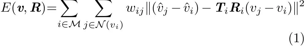
The matrixTidefines the desired affine mapping for transforming the local surface elements.
3.1.1Solving for anisotropic ARAP
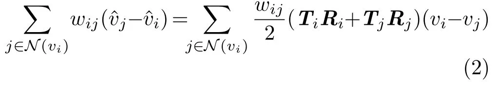
In the spirit of the work by Sorkine and Alexa[7]the solution for the best vertex positions is found in an iterative flip- flop fashion with a local phase and a global phase.In the local phase,we achieve this by additionally transforming the reference vertices bywhen seeking the best rotations–this holds for transformations with no rotation part.To solve for the best global vertex positions,our method directionally transforms the reference shape’s vertices as well.sparse linear system is built from the partial derivatives of the AnARAP energy with respect to the reference shape’s positionsRegarding a vertexvi,the equation is written as
When using local trans formations that include rotations,the local phase has to be modified.Solving this step seeks the rotation that aligns two fans rigidly. Performing this step for rotated target geometrieswill cause ARAP deformation to counteract the rotation,which is not the desired effect. Instead,we compare the deformed fan in the local phase to a transformed target without the rotational portion.
3.2 Anisotropic deformation gradient
Modeling with anisotropy is not restricted to ARAP deformation.Some shapes exhibit organic behaviour when deforming them using ARAP methods,and this may not always be intended by the user.Therefore,we introduce the same intuition to the method ofdeformation transfer[9]to enable anisotropic modeling.The original work represents a mesh’s deformation as a collection of per-triangle affine transformations.This encoding subsequently is used to decode a topologically equivalent mesh which leads to a deformation transfer.Our method follows this basic intuition and encodes a source which–in the decoding step–is applied to the original mesh in order to deform it.In contrast,our source transformations are not derived from a mesh,but we directly use the desired edits as an encoding.The initial transformationfor a trianglejis the identityA decoding of the mesh using this set of identities will not cause a deformation.As in the anisotropic ARAP extension,the user defines a set of vertices and a direction dependent transformation(e.g.,scaling,rotation,or shear)to drive the deformation.UsingAnDefGrad,we replace the initially set identities for affected triangles by the desired local transformationAs a result,the encoding for a deformation iswithbeing the set of triangles anda 3×3 affine matrix for affected triangles;is used for unaffected triangles.To decode the mesh with the desired transformations,we solve the sparse linear system:

with the unknown deformed vertex positions˜vand the weight-sensitive adjacency matrix:
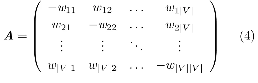
Note thatwijis zero whenever the verticesiandjdo not share an edge.Adjacency weights between two vertices depend on the adjacent triangles to this edge.wiiis the summed edge weight for all edges adjacent to the vertexi.The right-hand sidecis the sum of each disjunct triangle corner position PFor efficiency reasons,we pre-factorize the matrixonce and solve the system for spatially separated positions.Figure 2 depicts the difference between the ARAP based and the deformation gradient based anisotropic deformation methods on an example,for a scaling of the orange vertices.In contrast to the modified ARAP method,this method leads to a more local solution and the triangle deformation at the selection boundary exhibits a higher discontinuity.Depending on the need(a more organic versus a more articulated style of feature preservation),one of the two methods can be selected.
3.3 Local affine transformations
3.3.1Anisotropic scaling
One possible transformationis a scaling along a local vector field.Withsuandsvas the scale-factors in vertexi’s tangent plane,the matrix is de fined as

Ciis the local basis of the vertexvialigned to the desired direction of deformationci:
Figure 3(top)shows the scaling in a local vertex–fan space.
Anisotropic shearing.Using an affine shearing to deform the surface of a mesh follows the same principle as directed scaling.The per-vertex applied matrixTisimply is modified to be a local shearing(exemplary for a shear along thex-axis):

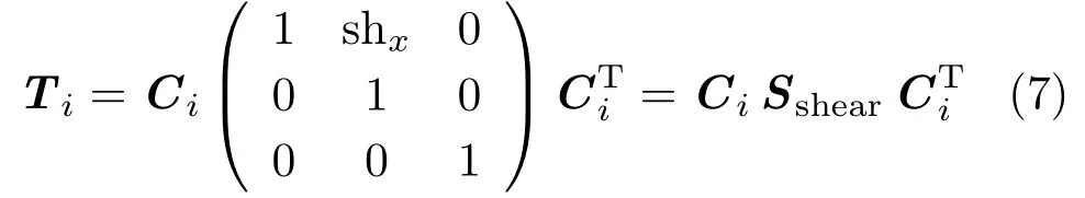
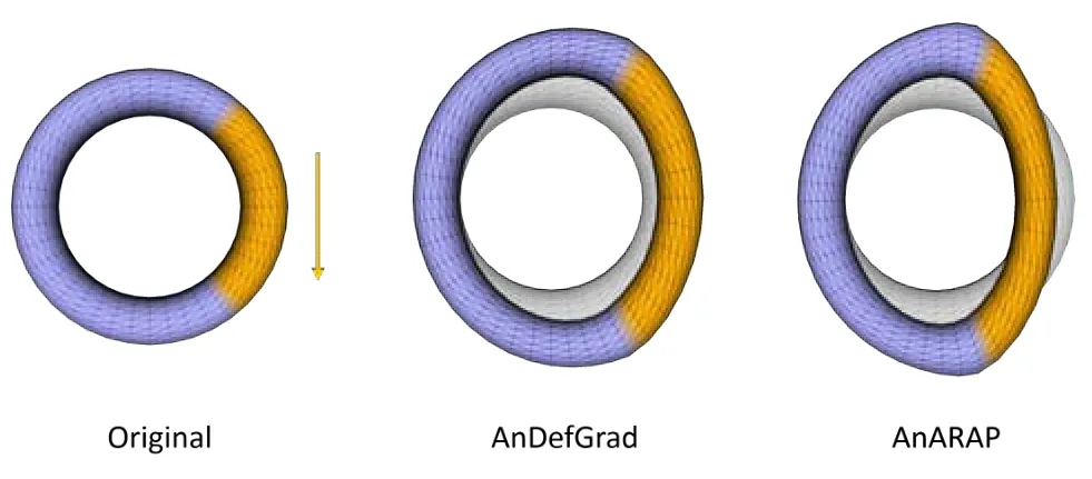
Fig.2 Parts of a torus(left)are elongated using anisotropic deformation gradients(middle)and ARAP deformation(right).While the deformation gradient based method exhibits a high discontinuity of triangle sizes,the deformation using anisotropic ARAP deformation is distributed more globally over the selection border.
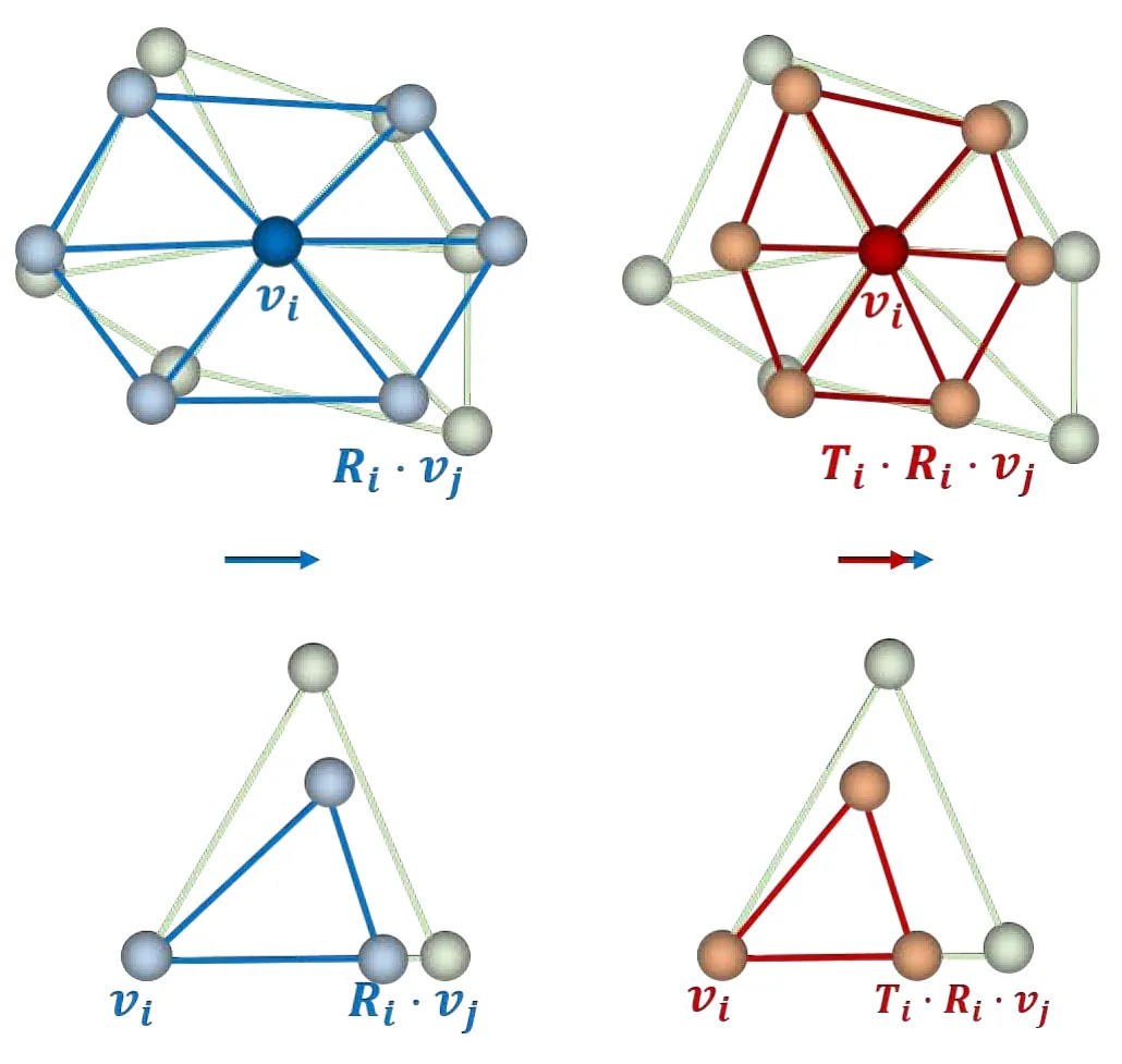
Fig.3 Top:instead of aligning the currently deformed vertex fan(green)to the reference mesh’s fan(blue),we scale the neighborhood ˆviby the directed scaling Ti(red).Bottom:the triangle case for the parameterization is shown accordingly.
With this,a geometry can be sheared,as depicted in Fig.4.
3.3.2Anisotropic rotation
In the same fashion,local rotations are performed by a simple modification toTi.Replacing the local transformationSby a rotation matrix leads to


Fig.4 The original geometry(left)is sheared using AnARAP(middle)as well as AnDefGrad(right)deformations.The organic appearance of ARAP is visible.The modified deformation gradient method gives more control.The orange regions are involved in the deformation while the blue ones are unaffected.
The organic character of ARAP leads to less predictable results due to the organic fashion of the deformation(see Fig.5(middle)).For certain scenarios and low strengths,this appearance is preferable to the results of the gradient-based method(see Fig.5(right)).
3.4 Deformation directions
The local frame to which the transformations are aligned is spanned by the normaland the tangent vectorsand. In the present work we give several possibilities for creating deformation directions.Avector fieldfollowing principal curvature directions[17]is used for the snake example in Fig.8.Theprojection of screen space directionsonto the surface enables an intuitive way of modeling without the need for a previously determined vector field. However,this method is obviously limited to directions which are not parallel to the surface’s normal direction.Finally,aglobal directioncan immediately be used as the deformation direction(see Figs.4,5,and 6).
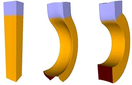
Fig.5 The post(left)is rotated locally at the selected vertices to become a hook.The AnARAP approach(middle)exhibits more global deformation while AnDefGrad(right)has more local control.
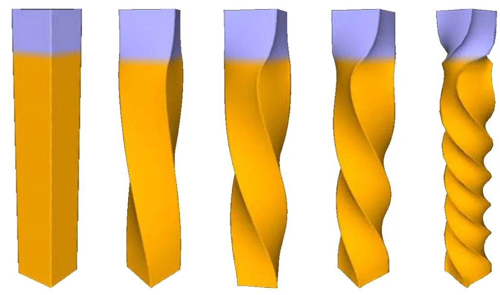
Fig.6 The selected(orange)vertices of the post are twisted using anisotropic deformation gradients along a global direction.The twist angle increases with height.The torsion frequency is increased from left to right.
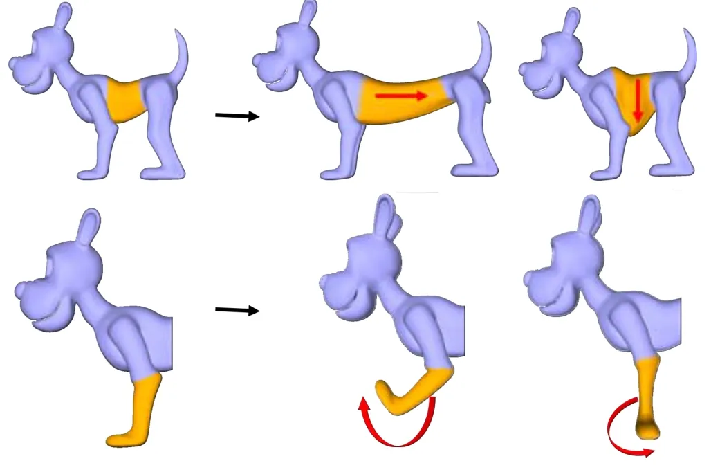
Fig.7 Anisotropic deformation is performed by selecting vertices(orange)and applying different classes of deformations. Top:a stretch transformation performs anisotropic scaling along the desired direction. Bottom: a local rotation of the surface elements is performed for two different rotation axes.The blue regions remain unaffected and,therefore,act as deformation constraints.
Elongation of parts can be achieved using a skeleton which involves tedious and unintuitive rigging.By interpolating the bone transformations,it is even possible to achieve a spatial dependency of deformation directions.Our method not only eases this process by allowing on-surface direction control,but it expands this possibility by allowing arbitrary,even procedural or user-painted deformation directions.This is demonstrated in facial expression modeling in Fig.10(top),where the direction field varies its orientation across the lips.
4 Applications and results
4.1 Modeling with the directional method

Fig.8 A curvature-aligned direction field is used to deform the snake.Top:the snake is scaled parallel to the field to elongate it–its thickness is well preserved.Bottom:deformation is performed perpendicular to the field to achieve a thickening–its length is well preserved.
Using the presented directional modeling approach,a user can select parts of an object and perform deformation along arbitrary directions. In doing so,a set of vertices is selected and different local transformations can be applied. The shape intuitively deforms accordingly. In Fig.7,local scaling and rotation transformations are depicted.The deformation is shown to follow the desired direction while the features are preserved. In contrast,the snake in Fig.8 was deformed along an automatically-defined vector field along the surface.A deformation parallel to the field elongates the snake maintaining its diameter,while scaling orthogonal to the field preserves its length.We compare the two different incarnations of our method to commonly used approaches in directional modeling: cage-based deformation(see Fig.9)and handle-based modeling via isotropic ARAP deformation. As the chess piece is elongated,significant features,e.g.,the rims below the head and at the bottom,should remain as similar as possible to their original shapes.The cage based approach stretches the shape uniformly,leading to less pronounced features. Likewise,AnARAP deformation produces a result which does not strongly preserves features–the shape becomes organic. This is an inherent property of ARAP methods,where edges are smoothed by three dimensional rotations of the fans. Naturally,the original ARAP method’s performance is poor as well. Using AnDefGrad preserves sharp features much better with respect to the original object,due to the highly local deformation approach of deformation gradients.In addition,the benefit of using an anisotropic formulation of the deformation in contrast to the regular(isotropic)energy is also shown in Fig.9.The original ARAP method is used to calculate the deformation for an elongated chess piece without considering anisotropy while using the inherently anisotropic deformation elongates the geometry in a more feature-preserving way,because the penalty is restricted orthogonally to the desired deformation energy.
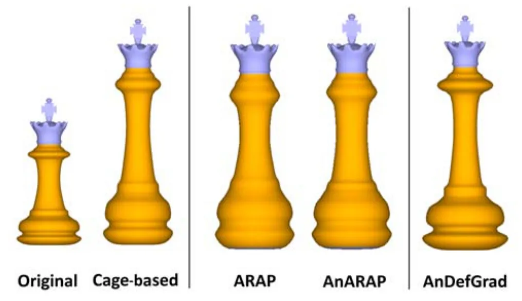
Fig.9 The original geometry(left)is linearly elongated using single cage-based deformation. Regular ARAP deformation and anisotropic ARAP deformation(AnARAP)results are shown in comparison.Note that feature sharpness is lost using an isotropic energy formulation.Overall,ARAP–with or without anisotropy–does not perform as well at sharp edges as the anisotropic deformation gradient modeling(AnDefGrad).
4.1.1Facial sculpting

Fig.10 Top:the vector field(left)is bent along the lips to cause the Roman bust(middle)to smile(right).Bottom:the beard is elongated along a vector field on the surface.
We present an other strength of the method by altering the facial expression of an ancient Roman bust using anisotropic deformation(see Fig.10(top)).A vector field is defined across the lips which changes direction depending on the distance to the corners of the mouth.AnARAP deformation is used to stretch the surface along the altering field leading to a different but still articulated expression.This result is achieved with little modeling input–a vector field changing over surface and a deformation strength is defined–and thus,it is highly accessible to the user.To show that even high-frequency features are well preserved,we elongate the beard of the face as shown in Fig.10(bottom).Here,the beard becomes longer following a constrained direction defined on the surface.
4.2 AnARAP parameterization for compression garments
Our method is not restricted to mesh deformation for the purpose of sculpting-inspired modeling.We show that the directional scaling can be applied to the parameterization method introduced by Ref.[13].Since our directional scaling is invariant to the surface elements(triangles or fans)used,the method can easily be used to also enrich the above formulation by adding anisotropy(see Fig.3(bottom)). Using anisotropy for free boundary parameterization solves an important issue in apparel design: flattening cut pieces for cloth production with proper compression scaling.Functional garments are important in the field of sports,and garment development pipelines are more and more influenced by virtual technologies.Including compression into the cloth is usually achieved by shrinkage of the flat cut piece. To increase compression while not shortening the garment,this scaling currently is performed nonuniformly along one single direction in 2D.This makes it hard to properly shrink patterns with more complex shapes deviating from this single direction.Our current methods allow us to define the shrinkage for local positions independently,and in 3D.Forcing the directionscifor some target verticesvion the surface gives the user control over the compression behavior at desired positions(see the arrows below the armpit in Fig.11(left)).In this example,compression is applied to support the area below the arms.The constrained compressions are propagated over the whole surface patch and the cut piece is computed by flattening the original surface subset. Solving for the best parameterization while taking the local,directed shrinkage into account leads to the desired compression scaling even for complex shapes.In contrast to state-of-the art shrinkage (Fig.11(scaled)), our approach distributes compression along defined field directions(Fig.11(AnARAP)).The anisotropic parameterization for garment pattern development was used to extend the pipeline presented in Ref.[18].Figure 12 shows a short pipeline overview of how user-defined shrinkage-directions result in a sewn functional garment with the desired compression behavior.

Fig.11 The desired compression directions are de fined for a patch(left). The original method of scaling fails to distribute the compression well(middle).Our method maintains the desired compression over the whole surface.
5 Discussion
Limitations.The method presented exhibits a major limitation in the inconvenient need for a deformation direction as a user input.Although the method is based on a vector field distributed on surface,one can exchange the direction generation for more convenient and intuitive methods.As with many modeling methods,a high amount of deformation results in an inhomogeneous distribution of differently sized triangles. This is solvable by re-triangulation of the mesh but not considered further here because an expensive recalculation of the system matrix is required. AnDefGrad and AnARAP exhibit similar performance with respect to conservation of low-frequency shape features(see Figs.7 and 8).For high-frequency features(e.g.,creases and sharp borders)AnARAP performs worse than AnDefGrad(see Fig.9);it should only be used for organic shapes.However,AnARAP results in more continuous triangle sizes,which is well suited for low-frequency modeling(see Fig.2). Finally,the projection of global or screen directions onto the surface includes an obvious drawback:directions orthogonal to the surface result in undetermined behavior and need special treatment.
Conclusions.In this paper we have presented a method to enrich sculpting-and modeling-based mesh deformation,providing directional control of surface deformations. We have shown that the method allows intuitive deformation of surfaces,while maintaining semantic features of the original shape well. In contrast to other methods,the presented deformation paradigm does not rely on handles or constraints.Surface regions are selected and the deformation is directly applied to the selection.Different affine transformations:scaling,shearing,and rotation,are implemented in the framework for two exisiting deformation paradigms:ARAP deformation and deformation gradients.The method of generating deformation directions can easily be replaced. We have presented shape manipulation along different kinds of on-surface directions as well as surface-aligned anisotropy for facial modeling.As anisotropic scaling is applicable to mesh parameterization,it is well suited to solving an important restriction in functional apparel development.
Acknowledgements
We want to thank Blendswap artists Calore for the cobra,Metalix for the dog,and Nerotbf for the Roman bust.
[1]Magnenat-Thalmann,N.;Laperri`ere,R.;Thalmann,D.Joint-dependent local deformations for hand animation and object grasping.In:Proceedings on Graphics Interface,26–33,1988.
[2]Baran,I.; Popovi´c, J.Automatic rigging and animation of 3D characters.ACM Transactions on GraphicsVol.26,No.3,Article No.72,2007.
[3]Jacobson,A.;Sorkine,O.Stretchable and twistable bones for skeletal shape deformation.ACM Transactions on GraphicsVol.30,No.6,Article No.165,2011.
[4]Nieto,J.R.;Sus´ın,A.Cage based deformations:A survey.In:Deformation Models.Hidalgo,M.;Torres,A.M.;G´omez,J.V.Eds.Springer Netherlands,75–99,2013.
[5]Jacobson,A.; Baran,I.; Popovi´c,J.; Sorkine-Hornung,O.Bounded biharmonic weights for realtime deformation.Communications of the ACMVol.57,No.4,99–106,2014.
[6]Igarashi,T.;Moscovich,T.;Hughes,J.F.As-rigidas-possible shape manipulation.ACM Transactions on GraphicsVol.24,No.3,1134–1141,2005.
[7]Sorkine,O.;Alexa,M.As-rigid-as-possible surface modeling.In:Proceedings of the 5th Eurographics Symposium on Geometry Processing,109–116,2007.
[8]Wang,Y.;Jacobson,A.;Barbiˇc,J.;Kavan,L.Linear subspace design for real-time shape deformation.ACM Transactions on GraphicsVol.34,No.4,Article No.57,2015.
[9]Sumner,R.W.;Popovi´c,J.Deformation transfer for triangle meshes.ACM Transactions on GraphicsVol.23,No.3,399–405,2004.
[10]Sumner,R.W.;Schmid,J.;Pauly,M.Embedded deformation for shape manipulation.ACM Transactions on GraphicsVol.26,No.3,Article No.80,2007.
[11]Bærentzen,J.A.;Abdrashitov,R.; Singh,K.Interactive shape modeling using a skeleton-mesh corepresentation.ACM Transactions on GraphicsVol.33,No.4,Article No.132,2014.
[12]Usai,F.;Livesu,M.;Puppo,E.;Tarini,M.;Scateni,R.Extraction of the quad layout of a triangle mesh guided by its curve skeleton.ACM Transactions on GraphicsVol.35,No.1,Article No.6,2015.
[13]Liu,L.;Zhang,L.;Xu,Y.;Gotsman,C.;Gortler,S.J.A local/global approach to mesh parameterization.Computer Graphics ForumVol.27,No.5,1495–1504,2008.
[14]Zhang,Y.;Wang,C.C.L.WireWarping++:Robust and flexible surface flattening with length control.IEEE Transactions on Automation Science and EngineeringVol.8,No.1,205–215,2011.
[15]Smith,J.;Schaefer,S.Bijective parameterization with free boundaries.ACM Transactions on GraphicsVol.34,No.4,Article No.70,2015.
[16]Krzywinski, S.VerbindungvonDesignund KonstruktionindertextilenKonfektionunter Anwendung von CAE.TUDpress,2005.
[17]Crane,K.; Desbrun,M.; Schröder,P.Trivial connections on discrete surfaces.Computer Graphics ForumVol.29,No.5,1525–1533,2010.
[18]Colaianni,M.;Siegl,C.;Süßmuth,J.;Rott,F.;Greiner,G.Shape adaptive cut lines.In:Proceedings of the Eurographics Workshop on Graphics for Digital Fabrication,49–55,2016.
1 Computer Graphics Group, University Erlangen-Nuremberg, 91058 Erlangen, Germany. E-mail:M.Colaianni,matteo.colaianni@fau.deC.Siegl,christian.siegl@fau.de;F.Bauer,frank.bauer@fau.de;G.Greiner,guenther.greiner@fau.de.
2Adidas AG,Adi-Dassler-Strasse1,91074 Herzogenaurach,Germany.E-mail:jochen.suessmuth@adidas-group.com.Manuscript
2017-03-07;accepted:2017-05-30

MatteoColaianniis a Ph.D.candidate in the Computer Graphics Group of the University of Erlangen-Nuremberg. His research focus is geometry processing in the field of apparel design and statistical shape analysis.

Christian Sieglis a Ph.D.candidate in the Computer Graphics Group of the University of Erlangen-Nuremberg.His research focuses on mixed-reality using projection mapping, medicalimage processing,and the virtual creation of apparel.

JochenSu¨ßmuthcompletedhis Ph.D.degree on geometry processing in Erlangen University in 2011.After that,he joined the Adidas group where he is currently working as a researcher in the field of computer graphics.

Frank Baueris a research fellow in the Computer Graphics Group of the University of Erlangen-Nuremberg.His research focuses on 3D scene reconstruction, augmented, mixed and virtual-reality applications,and accessible human–machine interactions.

Günther Greineris the head of the Computer Graphics Group of the University of Erlangen-Nuremberg.His research focuses on geometry processing and geometric modelling.
Open AccessThe articles published in this journal are distributed under the terms of the Creative Commons Attribution 4.0 International License(http://creativecommons.org/licenses/by/4.0/), which permits unrestricted use,distribution,and reproduction in any medium,provided you give appropriate credit to the original author(s)and the source,provide a link to the Creative Commons license,and indicate if changes were made.
Other papers from this open access journal are available free of charge from http://www.springer.com/journal/41095.To submit a manuscript,please go to https://www.editorialmanager.com/cvmj.
杂志排行

Computational Visual Media的其它文章
- Lighting transfer across multiple views through local color transforms
- Object tracking using a convolutional network and a structured output SVM
- Image-based clothes changing system
- Z2traversal order:An interleaving approach for VR stereo rendering on tile-based GPUs
- Face image retrieval based on shape and texture feature fusion
- Editing smoke animation using a deforming grid