Analysis and control of the compaction force in the composite prepreg tape winding process for rocket motor nozzles
2017-11-20HeXiaodongShiYaoyaoKangChaoYuTao
He Xiaodong,Shi Yaoyao,Kang Chao,Yu Tao
School of Mechanical Engineering,Northwestern Polytechnical University,Xi’an 710072,China
Analysis and control of the compaction force in the composite prepreg tape winding process for rocket motor nozzles
He Xiaodong,Shi Yaoyao*,Kang Chao,Yu Tao
School of Mechanical Engineering,Northwestern Polytechnical University,Xi’an 710072,China
Compaction;Composite material;Rocket nozzles;Parameter estimation;Voids;Winding processes
In the process of composite prepreg tape winding,the compaction force could influence the quality of winding products.According to the analysis and experiments,during the winding process of a rocket motor nozzle aft exit cone with a winding angle,there would be an error between the deposition speed of tape layers and the feeding speed of the compaction roller,which could influence the compaction force.Both a lack of compaction and overcompaction related to the feeding of the compaction roller could result in defects of winding nozzles.Thus,a flexible winding system has been developed for rocket motor nozzle winding.In the system,feeding of the compaction roller could be adjusted in real time to achieve an invariable compaction force.According to experiments,the force deformation model of the winding tape is a time-varying system.Thus,a forgetting factor recursive least square based parameter estimation proportional-integral-differential(PID)controller has been developed,which could estimate the time-varying parameter and control the compaction force by adjusting the feeding of the compaction roller during the winding process.According to the experimental results,a winding nozzle with fewer voids and a smooth surface could be wounded by the invariable compaction force in the flexible winding system.
1.Introduction
Resin matrix fiber reinforced composites have been widely used in aerospace engineering and other fields for their advantages such as high specific strength,high specific modulus,and thermal stability.Resin prepreg tape winding is a major method to manufacture a rocket motors nozzle’s aft exit cone.1The aft exit cone is used to provide the internal contour to expand the exhaust gases in solid rocket motors.Because of the high-temperature and high-speed exhaust gases,the aft exit cone is eroded during motor firing.2According to thehigh-temperature thermo-mechanical behavior of composites,Mcmanus and Springer investigated a model of voids formation rates caused by vapor and volatile,stress and strain,and damage of carbon fiber resin matrix composites with certain ply angle at high temperature.3Mouritz et al.analyzed the fire structural response of fiber–polymer laminates.4Bianchi et al.researched the thermo-chemical erosion behavior of a carbon-phenolic material in solid rocket motor nozzles.5McGurn et al.developed a thermal model for the response of carbon-epoxy composite laminates in fire environments,which includes porosity,mass fractions,and volume expansion ratio.6According to the researches,a low-porosity and intimately bonded winding product could have a better performance in high-temperature environments.
In order to decrease voids,Costa et al.showed the influence of the porosity in carbon fiber/epoxy resin and carbon fiber/bismaleimide resin composites on material performance.7Madsen and Lilholt built a theoretical model for the effect of the void phenomenon on unidirectional fiber composite performance.8Koushyar et al.focused on the phenomenon of carbon fiber/epoxy prepreg growing under hot pressing and vacuum.9Wu et al.researched the inter phase of a carbon fiber composite using transmission electron microscopy.10Pitchumani et al.designed and optimized a double compaction roller process to reduce the voids fraction in thermoplastic impregnated fiber tow placement.11Sha et al.measured and analyzed the fiber matrix interface strength of carbon fiber reinforced resin matrix composites,and it was shown that a slight pressure after completing the stick of fiber could reduce voids.12Tierney and Gillespie researched the void dynamics in a thermoplastic composite tow-placement process,and according to their research,the void could be reduced by optimizing the process parameters such as compress pressure and temperature.13Stokes-Griffin et al.researched a laser-assisted thermoplastic tape placement process,and the voids in the products could be decreased by thermal compaction.14
In the process of resin prepreg tape winding,an incoming tape is bonded to the deposition of tape layers by means of the contact pressure.15,16A compaction roller has been widely used to produce the contact pressure.Rudd et al.designed a pneumatic compaction roller for composite placement.17Gangloff et al.developed a process model for saturation of partially impregnated thermoset prepreg tapes with a compaction roller18Hassan et al.analyzed heat transfer for composite placement with a steel compaction roller.19Aized and Shirinzadeh optimized the composite placement process by a robot with a compaction roller.20
Because of the ablation in a rocket motor nozzle,there would be a phenomenon of layer lifting in winding products when the winding tape was parallel to the centerline of the mandrel.In order to reduce the phenomenon of layer lifting,the winding tape should be oriented at a winding angle to the centerline of the mandrel.21–24
The feeding direction of the compaction roller and the compaction force was non-orthogonal because of the winding angle.Thus,the compaction force could be influenced by the feeding of the compaction roller.The porosity of the composite component could be affected by the fluctuation of the compaction force.
In order to reduce the voids produced by the fluctuation of the compaction force,a flexible winding system has been developed in the presented study.According to the analysis and experiment for the porosity,the compaction force,and the feeding speed of the compaction roller,a forgetting factor recursive least square based parameter estimation PID controller has been designed to achieve an invariable compaction force by adjusting the feeding of the compaction roller in real time.
2.Resin prepreg tape winding process
During the composite tape winding process,a resin prepreg carbon fiber/glass fiber tape was wounded on a spindledriven mandrel,and the deposition of tape layers was consolidated by the combined action of compaction force,tape tension,and heating temperature,while a compaction roller was used to produce the compaction force on the incoming tape and the deposition of tape layers.The compaction force could decrease voids in winding products and enhance the bonding of tape layers.The winding process is shown in Fig.1.
In the aft exit cone of the rocket motor nozzle,the tape layers should be oriented at a winding angle to the centerline in order to reduce the propensity for ply lifting caused by the high-speed,high-temperature gas flow,as shown in Fig.2.
During the tape winding process,the compaction roller was moving along the mandrel to wrap the incoming resin prepreg tape onto the deposition of the tape layers as shown in Fig.3.Thus the tape would be consolidated together and the voids in the tape layers could be extruded by the compaction force.
The feeding speed of the compaction roller on the mandrel surface should be identical to the deposition speed of the tape layers.The deposition of the tape layers could be calculated by the spindle rotation speed and the thickness of the resin prepreg tape,24as follows:

wherevDis the deposition speed of the tape layers,nis the rotation of the spindle,h is the winding angle,a is the exit cone angle of the nozzle,and d is the thickness of the winding tape.
During a practical winding process,the tape thickness can be deformed due to the compaction force,and there would be errors in the resin dipping process,so this phenomenon would cause the change of the tape thickness,which could result in errors between the movement of the compaction roller and the deposition of the tape layers.
The deposition of the tape layers would be compressed or relaxed by the error between the movement of the compaction roller and the deposition of the tape layers,and thus there would be a fluctuation of the compaction force in the standard winding process,by which the winding product could be influenced.
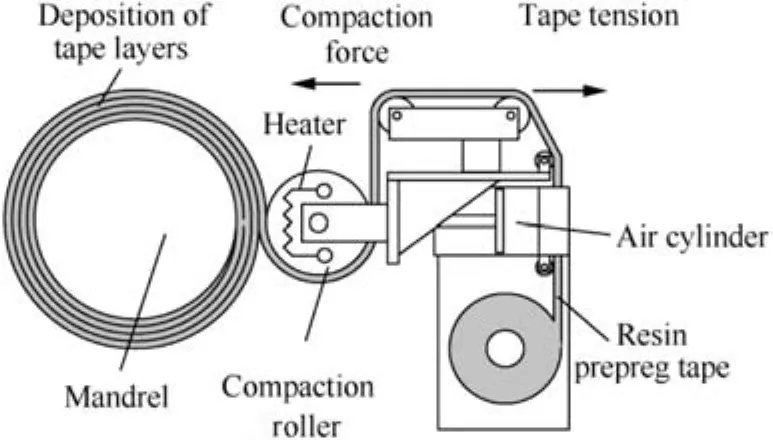
Fig.1 Tape winding process.
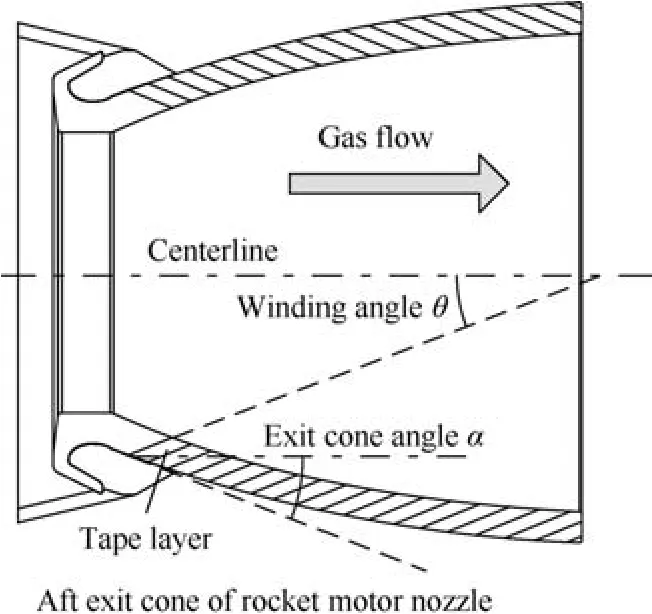
Fig.2 Resin prepreg tape wound rocket motor nozzle with a winding angle.
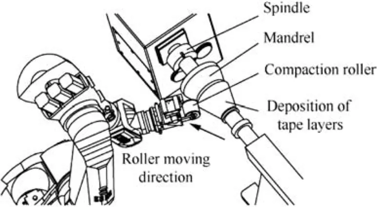
Fig.3 Tape winding process with a winding angle.
3.Relationship between voids,compaction force,and feeding speed of the compaction roller
3.1.Relationship between voids and compaction force
In the winding process,the incoming winding tape would be consolidated at the contact surfaces by the compaction force.During the consolidation,the contact surfaces of the tape and the wound layer would be deformed smoothly and combined together.
As shown in Fig.4,the contact surfaces of the tapes could be replaced by surfaces with a series of rectangles which are a mixture of fiber and resin.The voids would be increased in the winding product if there is a lack of intimate contact during the winding process.25The voids were related to the contact time and the contact pressure during the winding process,so the voids could be decreased with an evenly compaction between the incoming tape and the deposition of the tape layers.26,27Thus the voids content of the winding product could be controlled by the speed of the incoming tape and the compaction force.
As noted above,in the winding process,the speed of the incoming tape could be controlled by the spindle rotation of the winding machine,and thus the contact time could be considered as a constant with a fixed speed of the incoming tape.The contact pressure is produced by the compaction force during the winding process.In a traditional winding system,the compaction force is produced by a pneumatic-cylinder-driven compaction roller.The compaction force and the movement of the compaction roller could be independent only when the directions of the compaction roller and the compaction force are orthogonal.
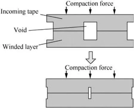
Fig.4 Combination of the resin prepreg tape.
3.2.Relationship of compaction force and feeding speed of compaction roller
During a non-zero winding angle application,the compaction roller is moving along the generatrix of the winding mandrel.As shown in Fig.5,the directions of the compaction force and the compaction roller movement are non-orthogonal,and thus the compaction force could be influenced by the movement of the compaction roller.The resin in the winding tape is viscous and the fiber is elastomeric,and thus the viscoelasticity behavior of the winding tape would be presented as a spring-damper model.28,29
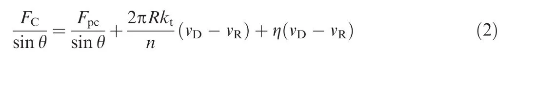
Fig.5 Compaction force influenced by the feeding speed of the compaction roller.
As shown in Fig.5,compared to the deposition speed of the tape layers,when a different feeding speed of the compaction roller is used in the winding process,the compaction force of the incoming tape and the deposition of the tape layers would be changed.It could be expressed as whereFCis the compaction force between the incoming tape and the deposition of the tape layers,Fpcis the force produced by the pneumatic cylinder,Ris the radius of the mandrel,ktis the stiffness of the winding tape,g is the damping of the tape,andvRis the feeding speed of the compaction roller.
As noted above,the degree of intimate contact is related to the compaction force,and a lack of the degree of intimate contact would cause voids in the winding product.According to Eq.(2),there is a negative correlation between the compaction force and the feeding speed of the compaction roller.Thus,the voids of winding product could be decreased when the feeding speed of the compaction roller is decreased.
In order to verify the relationship between the voids of a winding product and the feeding speed of the compaction roller,a winding experiment noted blow has been conducted,and five products with different feeding speeds of the compaction roller have been wounded in the experiment.
3.3.Relationship between feeding speed of compaction roller and voids
The winding experiment is shown in Fig.6,during which the compaction roller was driven by a pneumatic cylinder and the compaction force was produced by the pneumatic cylinder.The pneumatic cylinder was controlled by a FESTO MPPES-1/4-6-010 proportional pressure regulator,and the maximum control error of the regulator is 0.5%.Both the compaction roller and the pneumatic cylinder have been assembled on a robot.The winding tape could be softened at 35℃,and the curing temperature of the winding tape is 115℃.Thus,the winding temperature was set to 50℃.In order to achieve the winding temperature,the mandrel was pre-heated in an oven at 55℃ for 30 min before the winding process.During the winding process,the measured winding temperature was in a range from 53.6℃ to 48.2℃.
Epoxy resin prepreg carbon fiber tape was used in the experiment.Theresin prepreg tapewasproduced by ZhongFuShenying Carbon Fiber Ltd.,the resin was Epoxy YH-69,the fiber was Carbon T-300,and the amount of fibers was 62%.All of the winding parameters were set to constants as shown blow in the experiment except the feeding speed of the compaction roller.The average thickness of the tape was 0.22 mm,the winding angle was 20?,the spindle rotation rate was 10 rpm,the radius of winding mandrel was 160 mm,the pressure of pneumatic cylinder was 0.2 MPa,the area of the pneumatic cylinder was 5026.5 mm2,thus the compaction force produced by the pneumatic cylinder was 1005.3 N,and the width of the winding tape was 25 mm.All of the products were cured at 150℃ and 0.1 MPa for about 120 min.
According to the tape thickness and Eq.(1),the basic feeding speed of the compaction roller for the experiment products was 6.43 mm/min,while others were 5.8,5.2,4.6,and 4 mm/min,respectively.The cured products were manufactured to be 166 mm in external diameter and 30 mm in length.The specimens of winding products are shown in Fig.7.
The winding parameters of the specimens are shown in Table 1.
The voids in the winding products would decrease the densities of the products.Thus the voids of the winding products in the experiments could be expressed as the densities of the winding products,and the results of the experiment are shown in Fig.8.
According to the results,the density of a winding product was increased with the decrement of the feeding speed of the compaction roller for the first three products.With further decrement of the feeding speed,the density became decreased for the fourth and fifth products.Therefore,both a faster and slower feeding speeds could result in a lack of density in a winding product,which means that the voids of the products could be related to the overcompaction.
With a slower feeding speed of the compaction roller,the contact area between the roller and the deposition of the tape layers would be compressed.The compaction force of the roller and the deposition of the tape layers would be increased as shown in Eq.(3).Despite being cylindrical,the winding mandrel’s surface along the winding angle is a conical surface.The winding direction is a circle on the conical surface,which is not a geodesic of the conical surface,and thus there was a sliding force between the prepreg tape and the deposition of the tape layers.30
During the winding process,the tape layers would be bonded together by the resin in the tape.The bonding effect would stabilize the sliding tape in the winding process with a winding angle.The increased contact force would squeeze out the resin in the prepreg tape,thus the bonding effect of the deposition layers would be weakened,and the tape layers would be slid during the winding process.
According to the micrograph(see Fig.9)and the external surface(see Fig.10)of the product wound with a slower feeding speed of the compaction roller,it could be verified that the deposition of the tape layers has been slid and wrinkled with a slower feeding speed of the compaction roller.
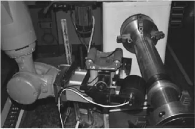
Fig.6 Winding experiment.

Fig.7 Winding products with different feeding speeds of the compaction roller.
All the analysis shows that the winding products could be relaxed or wrinkled by a faster or slower feeding speed of the compaction roller compared to the deposition speed of the tape layers in the winding process.Both the relaxation and the wrinkle could lead to an increment of the voids in winding products.
To eliminate this influence,the feeding of the compaction roller should be adjusted in real time to keep an invariable compaction force in the winding process.
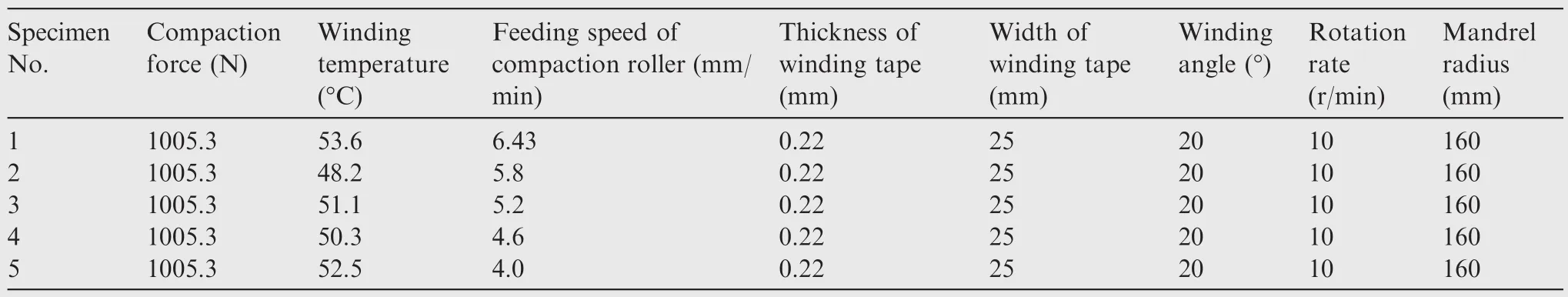
Table 1 Winding parameters of the specimens.
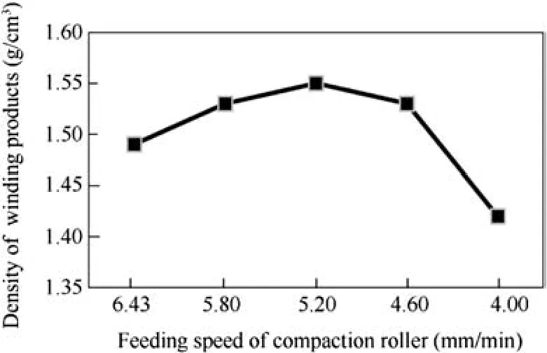
Fig.8 Densities of the experiment products.

Fig.9 Section of the winding product with a slower feeding speed of the compaction roller.
4.Design of a flexible winding system
According to the that noted above,during the winding process with a winding angle,there would be a fluctuation of the compaction force caused by the error between the deposition speed of winding tape layers and the feeding speed of the compaction roller.The fluctuation could increase the voids in winding products.
To eliminate the voids and achieve a smooth surface of the winding product,a flexible winding system has been developed to control the compaction force by adjusting the feeding of the compaction roller in the winding process.
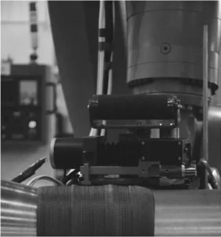
Fig.10 External surface of the winding product with a slower feeding speed of the compaction roller.
4.1.Force deformation model for winding tape
In order to control the compaction force invariably by adjusting the feeding of the compaction roller,a force displacement model of the winding tape should be achieved.
The resin in the winding tape is a viscous fluid and the fiber in the winding tape is an elastic body,and therefore,the forcedisplacement model of the winding tape contains both elastic and damp elements,and thus the force-displacement model should be a nonlinear and time-variant system.
With a force displacement model,it could be achieved to control the compaction force accurately by adjusting the winding head moving speed.As noted above,the force deformation model of the composite tape is a key factor to an accurate compaction force control.In order to research the force deformation model,a compaction experiment has been completed as shown in Fig.11.During the compaction experiment,a compaction roller was assembled on a robot without the pneumatic cylinder,and the winding tape was compressed by the robot at a certain distance as shown in Table 1,and thus the compaction force was produced by the compression of the winding tape.The compaction force was measured by a YZC-516 force sensor.
The force deformation model is shown in Fig.12,wheredis the compaction distance during the experiment.It could be seen that when the winding tape was compressed with certain distances(d=0.84,1.46,2.05,2.18,2.77 mm),the compaction force was reduced with time.According to Fig.12,the winding tape was relaxed during compaction.
The stiffness of the winding tapes in different compression deformations is shown in Table 2.
According to the results of the experiment,the relaxation of the winding tape layers was related to the compaction force and compaction time,so it could be considered as a slow time-varying system,in which the stiffness of the winding tape layers was a time-varying parameter and the change of the stiffness was slow and continuous.
The compaction force could be controlled accurately with an accurate force-deformation model,but only for a specified material,which is not appropriate in a universal winding process.
In order to have a universal control method,a forgetting factor recursive least square based parameter estimation PID controller has been designed for the winding system.In the controller,the parameters of the winding system such as the stiffness of winding tapes and the parameters of the winding machine could be identified in real time,and the slow timevarying parameter of the controller could be adjusted selfadaptively;therefore,an accurate compaction force could be finished.
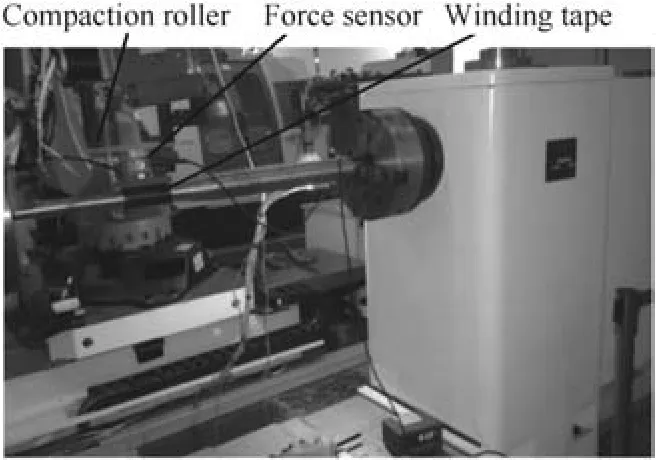
Fig.11 Compaction experiment of the winding tape.
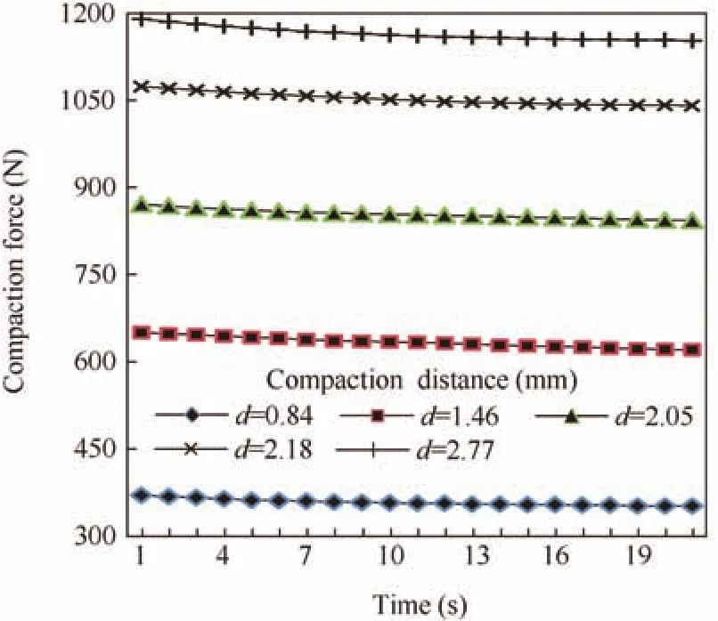
Fig.12 Force deformation model of the winding tape.
4.2.Parameter estimation controller of flexible winding system
As noted above,the compaction force could be produced by a certain compression distance between the compaction roller and the deposition of the winding tape,which could be calculated by the stiffness of the winding tape.Thus the flexible winding system has been developed to control the compaction force.During the flexible winding process,the stiffness of the winding tape could be estimated in real time and the compaction force could be controlled by adjusting the compression distance between the compaction roller and the deposition of the winding tape.The compression distance could be regulated by the flexible winding system with adjusting the feeding of the compaction roller.
The winding robot could be expressed as a two-order system,and the winding tape could be expressed as a slow timevarying proportion element,according to which,the compaction between the winding head and the winding tape could be expressed as31
Due to the reliability and easy accessibility,PID controllers have been widely used in industrial controls.A discrete incremental PID controller is shown as

In order to simplify the system,Eq.(4)could be transformed as

According to Eqs.(2)–(4),the output of the compaction force in the winding system could be expressed as

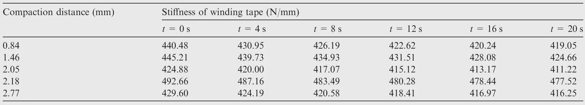
Table 2 Stiffness of the winding tape.
The output of the controller could be adjusted by the parameter functionG.Combined with the parameter estimation,the PID controller could adapt the change of the parameter.
According to the above,the stiffness of the winding tape is a slow time-varying parameter system.In order to estimate the time varying parameter,forgetting factor recursive least square has been used in the parameter estimation element.A weighting factor was used for the input data,the lasted data were weighted by one,and the datansampling periods before were weighted bynth power of the weight factor to weaken the estimated output from the old input.The parameter estimation of the controller is expressed as32
According to the equations,the process of the controller is shown in Fig.13.
A simulation of the forgetting factor recursive least square based parameter estimation PID controller has been accomplished.According to the force deformation model of the winding tape,the stiffness of the winding tape in the simulation was set to 450+30 sin(0.5t),k was set to 0.95 in the simulation,u(k)in the controller was the feeding increment order of the compaction roller in thekth sampling period,y(k)was the compaction force acquired in thekth sampling period,y1(k)was the expected compaction force in thekth sampling period,and the expected compaction force was a square wave,with the maximum being 500 N,the minimum being 250 N,the period being 5 s,and the sampling frequency being 40 Hz.The initial values of input and output were set to zero,and the initial estimation vector was set to[114401]T.Results of the simulation are shown in Figs.14 and 15.
According to the simulation results,the controller could follow the change of the parameter,and an accurate compaction force could be achieved.
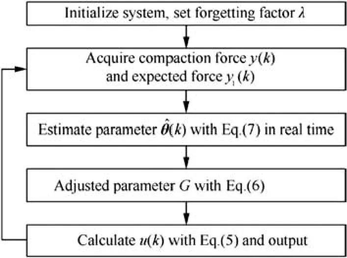
Fig.13 Process of the parameter estimation controller.
5.Experiments and results
As noted above,in order to avoid layer lifting in a rocket motor nozzle,there should be a winding angle during the composite prepreg tape winding process.The compaction force could be influenced by the feeding of the compaction roller during a non-zero winding angle application,and the fluctuation of the compaction force would lead to defects in the winding products.In order to achieve an invariable compaction force during the winding process for a rocket motor nozzle,a flexible winding system has been researched to control compaction force by adjusting the feeding of the compaction roller.A flexible winding experiment has been finished to validate the flexible winding system including compaction force control and quality inspection of winding products.
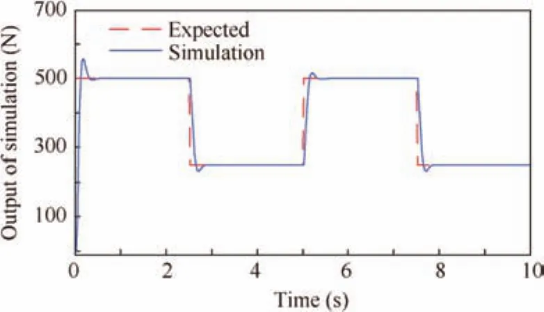
Fig.14 Simulation of the compaction force.
Epoxy resin prepreg carbon fiber tape was used to wind a cylinder nozzle in the flexible winding experiment.The experiment system is shown in Fig.16.The compaction roller was assembled on a KUKA KR-180 robot without a pneumatic cylinder,the flexible winding system adjusted the feeding of the compaction roller to regulate the compression distance between the compaction roller and the deposition of the winding tape,and the compaction force was produced by the compression between the compaction roller and the deposition of the winding tape.A SINAMIC 1FT7105 8 kW servo motor was used as the spindle of the winding machine,a YZC-516 force sensor was used to acquire the compaction force during the winding process,and a SIMATIC S7 300 PLC was used as the controller.
In the experiment,the winding angle was 20?,the tape width was 20 mm,the average tape thickness was 0.22 mm(20 points on the tape were measured),the mandrel rotation speed was 10 r/min,the winding temperature was set to 50℃,during the winding process,the measured winding temperature was in a range from 53.5℃ to 47.6℃,the expected compaction force was set to 800 N,and a 160-mm diameter cylinder mandrel was used.
The compaction force during the flexible winding process is shown in Fig.17.Despite an overshoot about 126 N at the starting of the control,the compaction was invariable during the winding process.According to Fig.17,an invariable compaction force during the winding process could be controlled by the forgetting factor recursive least square based parameter estimation PID controller.It could be verified that the controller could adjust the feeding of the compaction roller accurately by predicting the stiffness of the winding tape.
The deposition of tape layers in the flexible winding process of the experiment is shown in Fig.18.As noted above,during the winding process,the overcompaction caused by errors between the feeding speed of the compaction roller and the deposition speed of tape layers would lead to a wrinkled surface of the winding product.According to Fig.18,the wrinkled surface of a winding nozzle and the overcompaction could be avoided by the flexible winding system.Compared to the application of a slower feeding speed of the compaction roller(as shown in Fig.11),a smooth surface of the deposition of tape layers could be achieved in the flexible winding experiment.
The winding product was cured at 150℃ and 0.1 MPa for 120 min.The cured winding nozzle in the flexible winding experiment is shown in Fig.19.The external diameter of the nozzle is 172 mm and the length is 80 mm.
A specimen of the winding nozzle was cut off along the axial direction of the nozzle.The specimen was inspected by an electron microscope as shown in Fig.20.
The micrograph of the winding nozzle specimen in the flexible winding experiment is shown in Fig.21.
According to the that noted above,the fluctuation of compaction would increase the voids in a winding product.As shown in the micrograph of the flexible winding nozzle specimen,a winding product with fewer voids could be achieved with the flexible winding system.The density of the flexible winding nozzle is 1.58 g/cm3,higher than that of an ordinary winding product.According to Fig.21,the voids and the slid tape layers in the winding nozzle were decreased by the invariable compaction during the flexible winding process.The experiment results of flexible winding are shown in Table 3.
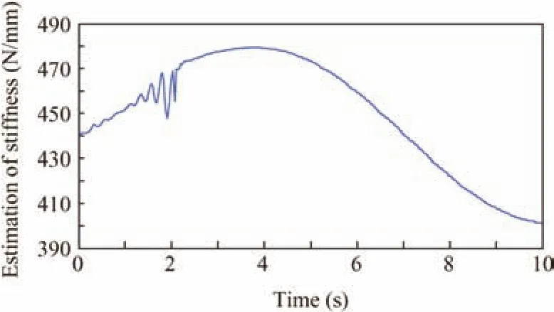
Fig.15 Estimation of the stiffness.
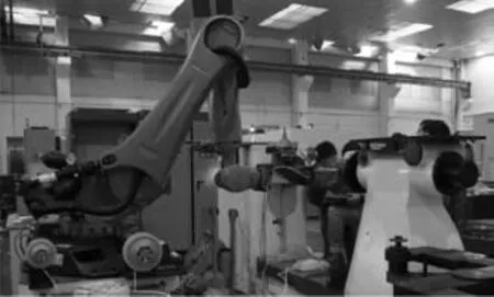
Fig.16 Flexible winding experiment.
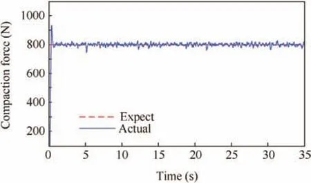
Fig.17 Compaction force during the flexible winding process.
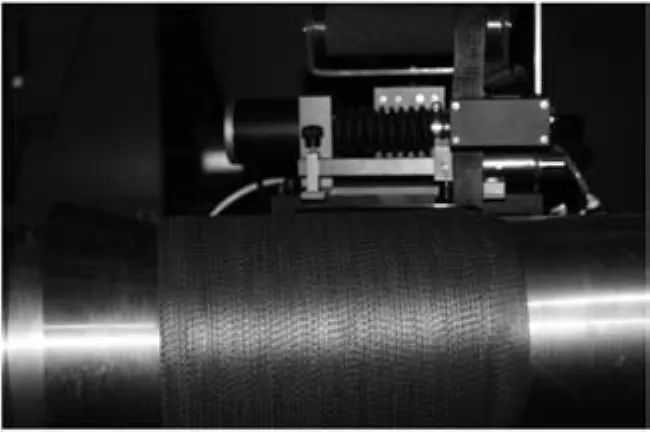
Fig.18 Deposition of tape layers in the flexible winding process.
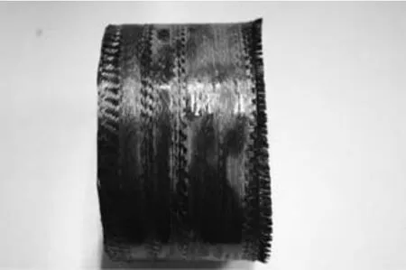
Fig.19 Flexible winding product.
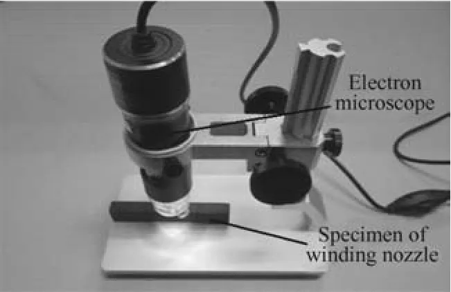
Fig.20 Specimen inspection with an electron microscope.
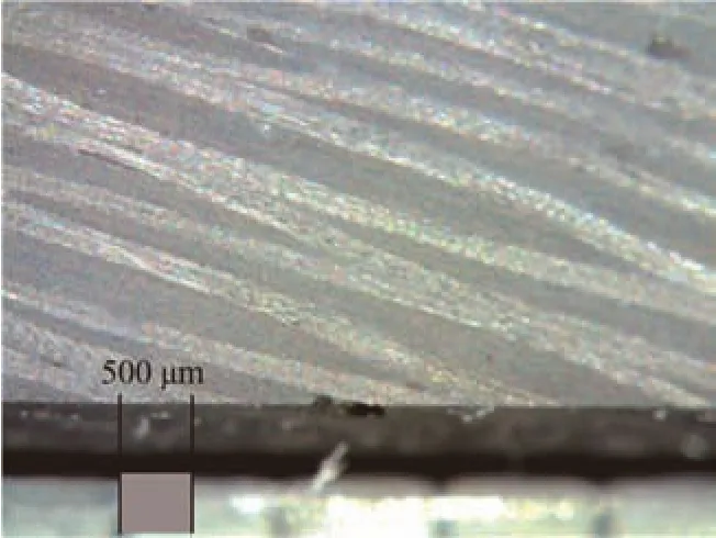
Fig.21 Section of the flexible winding product.
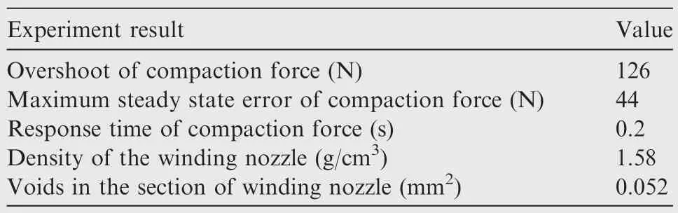
Table 3 Experiment results of flexible winding.
According to the results of the flexible winding experiment,the maximum error of the compaction force in a steady state was 5.5%.An invariable compaction force could be controlled by adjusting the feeding of the compaction roller in the flexible winding system,and the forgetting factor recursive least square based parameter estimation PID controller could estimate the stiffness of the winding tape.Both overcompaction and lack of compaction could be avoided during the flexible winding process.The voids in the winding nozzle were only 0.052 mm2for the invariable compaction,and thus the density of the winding nozzle was increased about 2–11.3%when compared to those of winding products in ordinary winding experiments.A cylinder nozzle with a smooth surface and fewer voids could be achieved by the invariable compaction force in the flexible winding system.
6.Conclusions
(1)During the composite prepreg tape winding process for a rocket motor nozzle with a winding angle,the quality of the winding product is related to the feeding speed of the compaction roller.According to the analysis and experiment,both faster and slower feeding speeds of the compaction roller could result in defects in winding products,such as voids,slid tape layers,and wrinkled surface.
(2)In order to reduce the defects in the winding process,the feeding of the compaction roller should be adjusted in real time to achieve an invariable compaction force during the winding process.According to the analysis and experiment,the force deformation model of the winding tape is a time varying parameter system.
(3)In order to control the compaction force with a time varying stiffness winding tape,a forgetting factor recursive least square based parameter estimation PID controller has been used in the flexible winding system.The winding system adjusted the feeding of the compaction roller by the parameter estimation PID controller during the winding process.
(4)According to the results of simulation and experiment,the flexible winding system has been proven feasible.Compared to ordinary winding products,a smooth surface could be achieved in the flexible winding process,and slid tape layers and voids of the flexible winding nozzle could be decreased.An accurate composite prepreg tape winding process could be guaranteed by using the flexible winding system.
Acknowledgment
This study was supported by the National Natural Science Foundation of China(No.51375394).
Appendix A.Supplementary material
Supplementary data associated with this article can be found,in the online version,at http://dx.doi.org/10.1016/j.cja.2016.07.004.
1.Scoccimarro D,Mucci R,Marocco R,Mataloni A,Mancini V,Genito M,et al.Zefiro 40 solid rocket motor:From a technological demonstrator to vega evolution flight stage.51st AIAA/ASME/SAE/ASEE joint propulsion conference;2015.
2.Bianchi D,Turchi A,Nasuti F,Onofri M.Chemical erosion of carbon-phenolic rocket nozzles with finite-rate surface chemistry.J Propul Power2013;29(5):1220–30.
3.Mcmanus HLN,Springer GS.High temperature thermomechanical behavior of carbon-phenolic and carbon-carbon composites,I.Analysis.J Compos Mater1992;26(2):206–29.
4.Mouritz AP,Feih S,Kandare E,Gibson AG.Thermal–mechanical modeling of laminates with fire protection coating.Compos B Eng2013;48:68–78.
5.Bianchi D,Turchi A,Nasuti F,Onofri M.Chemical erosion of carbon-phenolic rocket nozzles with finite-rate surface chemistry.J Propul Power2013;29(5):1220–30.
6.McGurn MT,DesJardin PE,Dodd AB.Numerical simulation of expansion and charring of carbon-epoxy laminates in fire environments.Int J Heat Mass Transf2012;55(1):272–81.
7.Costa ML,De Almeida SM,Rezende MC.The influence of porosity on the interlaminar shear strength of carbon/epoxy and carbon/bismaleimide fabriclaminates.ComposSciTechnol2001;61(14):2101–8.if ber/epoxy composite.J Compos Mater2012;46(16):1985–2004.
10.Wu Q,Li M,Gu Y,Zhang Z.Imaging the interphase of carbon fiber composites using transmission electron microscopy:Preparations by focused ion beam,ion beam etching,and ultramicrotomy.Chin J Aeronaut2015;28(5):1529–38.
11.Pitchumani R,Gillespie JW,Lamontia MA.Design and opti-
8.Madsen B,Lilholt H.Physical and mechanical properties of unidirectional plant fibre composites—an evaluation of the influence of porosity.Compos Sci Technol2003;63(9):1265–72.
9.Koushyar H,Alavi-Soltani S,Minaie B,Violette M.Effects of variation in autoclave pressure,temperature,and vacuum-application time on porosity and mechanical properties of a carbon mization of a thermoplastic tow-placement process with in-situ consolidation.J Compos Mater1997;31(3):244–75.
12.Sha JJ,Dai JX,Li J,Wei ZQ,Hausherr JM,Krenkel W.Measurement and analysis of fiber-matrix interface strength of carbon fiber-reinforced phenolic resin matrix composites.J Compos Mater2014;8(11):1303–11.
13.Tierney J,Gillespie JW.Modeling of heat transfer and void dynamics for the thermoplastic composite tow-placement process.J Compos Mater2003;37(19):1745–68.
14.Stokes-Griffin CM,Compston P,Matuszyk TI,Cardew-Hall MJ.Thermal modelling of the laser-assisted thermoplastic tape placement process.J Thermoplast Compos Mater2015;28(10):1445–62.
15.Kim HJ,Kim SK,Lee WI.A study on heat transfer during thermoplastic composite tape lay-up process.Exp Thermal Fluid Sci1996;13(4):408–18.
16.Littlefield A,Hyland E,Andalora A,Klein N,Langone R,Becker R.Carbon fiber/thermoplastic overwrapped gun tube.J Pressure Vessel Technol2006;128(2):257–62.
17.Rudd CD,Turner MR,Long AC,Middleton V.Tow placement studies for liquid composite moulding.Compos A Appl Sci Manuf1999;30(9):1105–21.
18.Gangloff JJ,Simacek P,Sinha S,Advani SG.A process model for the compaction and saturation of partially impregnated thermoset prepreg tapes.Compos A Appl Sci Manuf2014;64:234–44.
19.Hassan N,Thompson JE,Batra RC,Hulcher AB,Song X,Loos AC.A heat transfer analysis of the fiber placement composite manufacturing process.J Reinf Plast Compos2005;24(8):869–88.
20.Aized T,Shirinzadeh B.Robotic fiber placement process analysis and optimization using response surface method.Int J Adv Manuf Technol2011;55(1):393–404.
21.Canfield A,Clinton RG.Improved ablative materials for the ASRM nozzle.AIAA/SAE/ASME/ASEE 28th joint propulsion conference and exhibit;1992.
22.Yoo Y,Lee S.3-D finite element analysis for thermo-mechanical behavior of laminated carbon-phenolic composite ring.J Mech Sci Technol2011;25(7):1775–80.
23.Guery JF,Chang IS,Shimada T,Glick M,Boury D,Robert E,et al.Solid propulsion for space applications:an updated roadmap.Acta Astronaut2010;66(1):201–19.
24.Shi YY,Tang H,Yu Q.Key technology of the NC tape winding machine.Acta Aeronant Astronaut Sin2008;29(1):233–9[Chinese].
25.Mantell SC,Springer GS.Manufacturing process models for thermoplastic composites.J Compos Mater1992;26(16):2348–77.
26.Simacek P,Advani SG,Gruber M,Jensen B.A non-local void filling model to describe its dynamics during processing thermoplastic composites.Compos A Appl Sci Manuf2013;46:154–65.
27.Tierney J,Gillespie JW.Modeling of heat transfer and void dynamics for the thermoplastic composite tow-placement process.J Compos Mater2003;37(19):1745–68.
28.Pouresmaeeli S,Ghavanloo E,Fazelzadeh SA.Vibration analysis of viscoelastic orthotropic nanoplates resting on viscoelastic medium.Compos Struct2013;96:405–10.
29.Prawoto Y.Solid mechanics for materials engineers-principles and applications of mesomechanics.Morrisville:LuLu Enterprise Inc;2013.p.122–9.
30.Zhang P,Sun R,Zhao X,Hu L.Placement suitability criteria of composite tape for mould surface in automated tape placement.Chin J Aeronaut2015;28(5):1574–81.
31.Yu W,Rosen J.Neural PID control of robot manipulators with application to an upper limb exoskeleton.IEEE Trans Cybern2013;43(2):673–84.
21 March 2016;revised 12 April 2016;accepted 5 June 2016
Available online 15 October 2016
*Corresponding author.Tel.:+86 29 88492851.
E-mail addresses:aqiqia@gmail.com(X.He),shiyy@nwpu.edu.cn(Y.Shi),kaochao_017@163.com(C.Kang),scro00@163.com(T.Yu).Peer review under responsibility of Editorial Committee of CJA.
杂志排行

CHINESE JOURNAL OF AERONAUTICS的其它文章
- Dynamics of air transport networks:A review from a complex systems perspective
- ATM performance measurement in Europe,the US and China
- Network analysis of Chinese air transport delay propagation
- Robustness analysis metrics for worldwide airport network:A comprehensive study
- Evolution of airports from a network perspective–An analytical concept
- Methods for determining unimpeded aircraft taxiing time and evaluating airport taxiing performance