Influence of aircraft surface distribution on electromagnetic scattering characteristics
2017-11-20LiuDaweiHuangJunSongLeiJiJinzu
Liu Dawei,Huang Jun,Song Lei,Ji Jinzu
School of Aeronautic Science and Engineering,Beihang University,Beijing 100083,China
Influence of aircraft surface distribution on electromagnetic scattering characteristics
Liu Dawei,Huang Jun,Song Lei*,Ji Jinzu
School of Aeronautic Science and Engineering,Beihang University,Beijing 100083,China
Aircraft concept;Electromagnetic scattering characteristic;Horizontal polarization;MLFMA;Stealth;Surface distribution;Vertical polarization
In this paper,two typical stealth aircraft concepts(wing fuselage blended and flyingwing)were designed.Then three gradually changed surface distribution models with the same planform for each concept were created.Based on the multilevel fast multipole algorithm(MLFMA),the vertical polarization transmitting/vertical polarization receiving(VV)and horizontal polarization transmitting/horizontal polarization receiving(HH)radar cross section(RCS)characteristics were simulated with five frequencies between 0.1 and 1.0 GHz.The influences and mechanisms of aircraft surface distribution on electromagnetic scattering characteristics were investigated.The results show that for the wing fuselage blended concept,the VV RCS of this frequency range is higher than the HH RCS in most cases,while it is just the opposite for the flying-wing concept.As for the two aircraft concepts,the RCS levels of HH and VV both decrease with the frequency increasing,but the HH RCS has a faster downward trend.The surface distribution has little influence on HH RCS characteristics.On the contrary,it has a significant impact on VV RCS characteristics,and the amplitude of the VV RCS increases with the surface thickness.
1.Introduction
With the rapid development of radar technologies,lowobservability or stealth performance has become more and more important for modern battle planes.Taking the radar cross section(RCS)reduction as a goal,radar stealth technologies mainly include shape-stealth,material-stealth,active offset,etc.Among them,the shape-stealth technology is the most effective method for improving aircraft stealth performance.1Main shape-stealth technologies include edge parallel,wing fuselage blended,cancelled empennage,tilt-empennage,etc.For the purpose of stealth performance,some newgeneration stealth aircraft concepts have removed the vertical tail.
In recent years,a lot of works on aircraft shape stealth have been done and many results have been achieved.2–10In previous studies,most of the research focused on the effects of aircraft configurations,plane shape parameters,and airfoil parameters on stealth performance.However,little research has been conducted on the influence of aircraft surface distribution on aircraft electromagnetic scattering characteristics.For the overall design of stealth aircraft,the planform designis decided by performance indexes.Then according to stealth and aerodynamic characteristics,the aircraft surface distribution is iteratively designed.High scattering sources can be carried out by the design of the aircraft planform,while weak scattering sources(such as the traveling wave and creeping wave scattering)are mainly relative to the surface distribution.Therefore,the objective of this paper was to investigate the influence of aircraft surface distribution on electromagnetic scattering characteristics,and then get a regularity conclusion,which can provide a basic guidance for the aircraft multiobjective design of aerodynamic and stealthy performance.In this paper,two typical stealth aircraft concepts,i.e.,wing fuselage blended and flying-wing configurations, were designed.In order to investigate the influence of aircraft surface distribution on electromagnetic scattering characteristics,three gradually changed surface distribution geometrical models with the same planform for each concept were created used the CATIA software.Then based on the multilevel fast multipole algorithm(MLFMA),11the scattering characteristics of different surface distribution models were simulated and analyzed.
2.Geometrical configurations
Two kinds of typical stealth aircraft configurations were designed in this paper:the wing fuselage blended concept(X concept)and the flying-wing concept(Y concept).
Fig.1 shows the X concept geometrical dimensions.As can be seen in Fig.1,the X concept adopted the wing fuselage blended configuration.The aircraft length is 10 m,and the wing span is 9 m.Three characteristic sweep angles exist in the aircraft flat shape:the wing leading edge sweep angle is 40?,the sweep angle of the wing strake is 75?,and the wing trailing edge has a 15?sweep-forward angle.
In order to investigate the influence of wing fuselage blended aircraft surface distribution on electromagnetic scattering characteristics,three gradually changed surface distribution geometrical models with the same planform for the X concept were created(X_A,X_B,and X_C).For the X_A model,the aircraft spanwise cross section is symmetric parabola airfoil,and the airfoil relative thickness is set to 1%.Equivalent to a very thin plate,the X_A model represents the best stealth performance aircraft surface distribution for this planform.Relative to the X_A model,the X_B model has an increased back uplift surface,which contains a fuel tank and engine components.The X_C model is the actual complete wing fuselage blended aircraft model.Compared with X_B,a blocked inlet and engine cowling were added on the aircraft belly.The obliquity angles of the inlet side and front faces are 21.65?and 45?,respectively.
Fig.2 shows the Y concept geometrical dimensions.As can be seen in Fig.2,the Y concept adopted the flying-wing configuration.The whole wing span is 21.6 m,the length of the central fuselage is 7.8 m,the chord length of the outboard straight wing is 2.4 m,and the sweep angle is 35?.
Like the X concept,there are also three gradually changed surface geometrical models with the same planform for the Y concept(Y_A,Y_B,and Y_C).The Y_C model is the actual complete flying-wing aircraft model.Relative to the Y_C model,the Y_B model has the same outboard wing surface distribution,while the central fuselage surface thickness is reduced to that of the outboard wing.For the Y_A model,the aircraft spanwise cross section is symmetric parabola airfoil,and the airfoil relative thickness is set to 5%.Equivalent to a very thin plate,the Y_A model also represents the best stealth performance aircraft surface distribution for this planform.
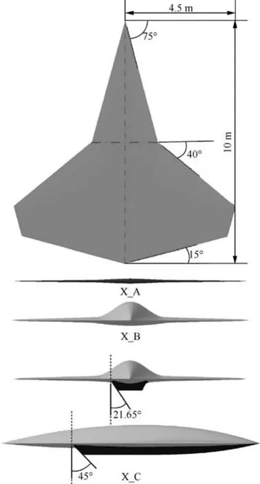
Fig.1 Wing fuselage blended aircraft geometrical dimensions and surface distribution.
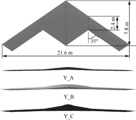
Fig.2 Flying-wing aircraft geometrical dimensions and surface distribution.
3.Numerical method and validation
3.1.Numerical method
At present,the main numerical simulation methods of aircraft RCS are high-frequency algorithms.1The major advantages of these algorithms are less time-consuming and low memory requirements.12However,they cannot precisely simulate the target surface current.In addition,they are not suitable to solve complex scattering targets,for instance,aircraft surface structure gaps or steps.13The method of moments(MOM)14has high calculation accuracy,but are limited to a required memory level and time-consuming,so the MOM cannot simulate large scatterers like aircraft.15The MLFMA is a highly efficient and precisely controlled algorithm.Owing to high precision and efficiency,the MLFMA has found wide applications in aircraft RCS calculations in recent years,16–19so in this paper,the MLFMA was used to numerically simulate the RCS characteristics of the aircraft models.
The basic principle of the MLFMA is that the combined field integral equation can be expressed by19,20
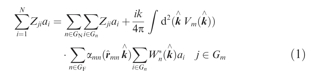
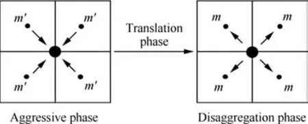
Fig.3 Implementation process of MLFMA.
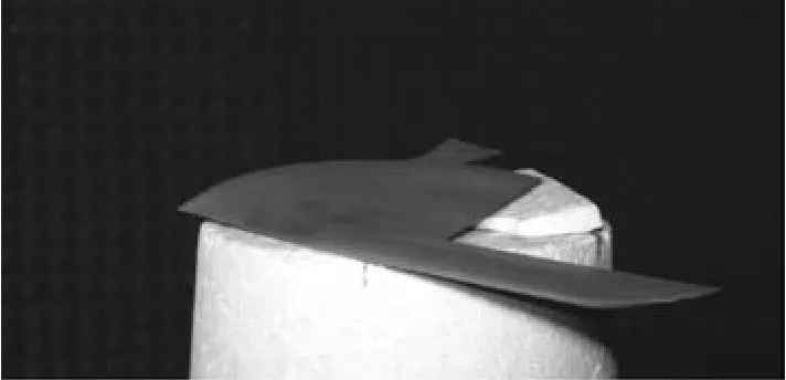
Fig.4 Electromagnetic test of a scaled flying-wing aircraft model in an anechoic chamber.

The matrix vector products computation process is divided into the near interaction which is calculated by the MOM and the far interaction which is divided with the MLFMA into three phases(Fig.3):aggressive phase,translation phase,and disaggregation phase.For the aggregation phase,the outgoing pattern is computed at the finest level by calculating the radiation patterns ofcorresponding sources,while acoarser-level calculation of the outgoing pattern is obtained through interpolation and shift from its child level.The incoming patterns of both top and lower levels are obtained through interpolation.
3.2.Numerical simulation method validation
In order to validate the numerical simulation method,an electromagnetic test of a scaled flying-wing aircraft model was conducted in an anechoic chamber(Fig.4).A 3D aircraft prototype was produced by the 3D printing technology.The initial conditions of the electromagnetic test and numerical simulation through the MLFMA were:the radiation frequency was 10 GHz,the pitching angle of the incident wave was set to 0?,the pitch and roll angles of the prototype were 0?,and horizontal polarization transmitting/horizontal polarization receiving(HH)and vertical polarization transmitting/vertical polarization receiving(VV)were adopted in the test and numerical simulation.The simulated and experimental HH and VV RCS curves are compared in Fig.5,in which u is the azimuth angle.From Fig.5 it can be seen that the simulated RCS spikes and curve trend are in good agreements with those determined by the electromagnetic test.All of these validate the numerical method and the simulated results of aircraft RCS characteristics in this study.
4.Presentation of results
4.1.Influence of surface distribution on RCS characteristics for wing fuselage blended concept
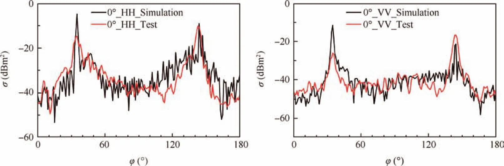
Fig.5 Comparison of RCS curves between MLFMA numerical simulation and electromagnetic test.
Figures 6 and 7 shows the HH and VV RCS characteristics of the wing fuselage blended concept.When the radiation frequency is 100 MHz,the VV RCS curve fluctuates little along the circumferential direction,and no significant RCS spike appears.As the radar radiation frequency rises to 300 MHz,the spike resulted by the characteristic swept angle becomes more and more significant.With the radar radiation frequency rising further,the vertical RCS spike widths of the three models of the X concept become narrow,and the X_A and X_B spike heights almost don’t change,while the X_C model RCS spikes have a downtrend which can be deduced by the result of the scattering field superposition of the fuselage surface and the leading-trailing edge.
A common characteristic exists for the VV RCS curves of the X_A,X_B,and X_C models,that is,the curve concussion levels are all below 10 dB as the radiation frequency increases.It can be deduced that this phenomenon is caused by the aircraft components surface size effect.The VV circumferential RCS values have a promotion of about 20 dB from the X_A model to the X_B model.This reflects that the thickness of the spanwise cross section has a significant influence on the VV RCS value.Comparing the X_C VV RCS curve with that of X_B,we can see that the spike located at the azimuth angle of 15?is replaced by a flat‘upland”;a new spike appears at the azimuth angle of 90?;a relatively high scattering region is formed by the spikes located at azimuth angles of 75?,90?,and 105?;the non-spike part of the RCS curve has an increase of about 10 dB and the average increment of the frontward RCS value is up to 20 dB.
For the same radiation frequency,the HH RCS curves of the X_A,X_B,and X_C models have the same spikes and trend.This indicates that in this frequency range,the vertical extend of the aircraft surface has less influence on the HH RCS characteristic of the wing fuselage blended concept.
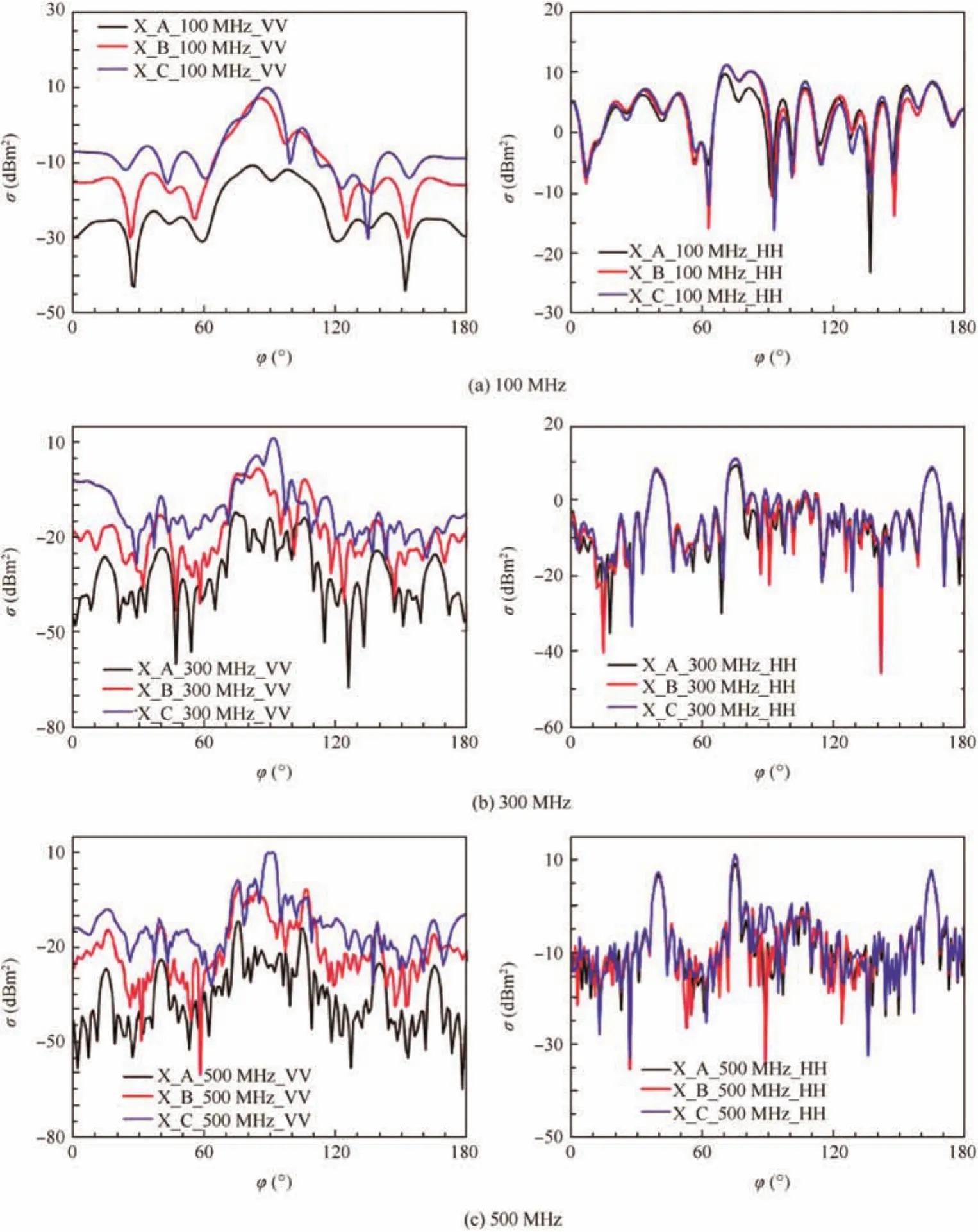
Fig.6 VV and HH RCS characteristics of wing fuselage blended aircraft(100–500 MHz).
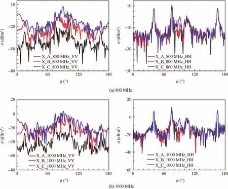
Fig.7 VV and HH RCS characteristics of wing fuselage blended aircraft(800–1000 MHz).
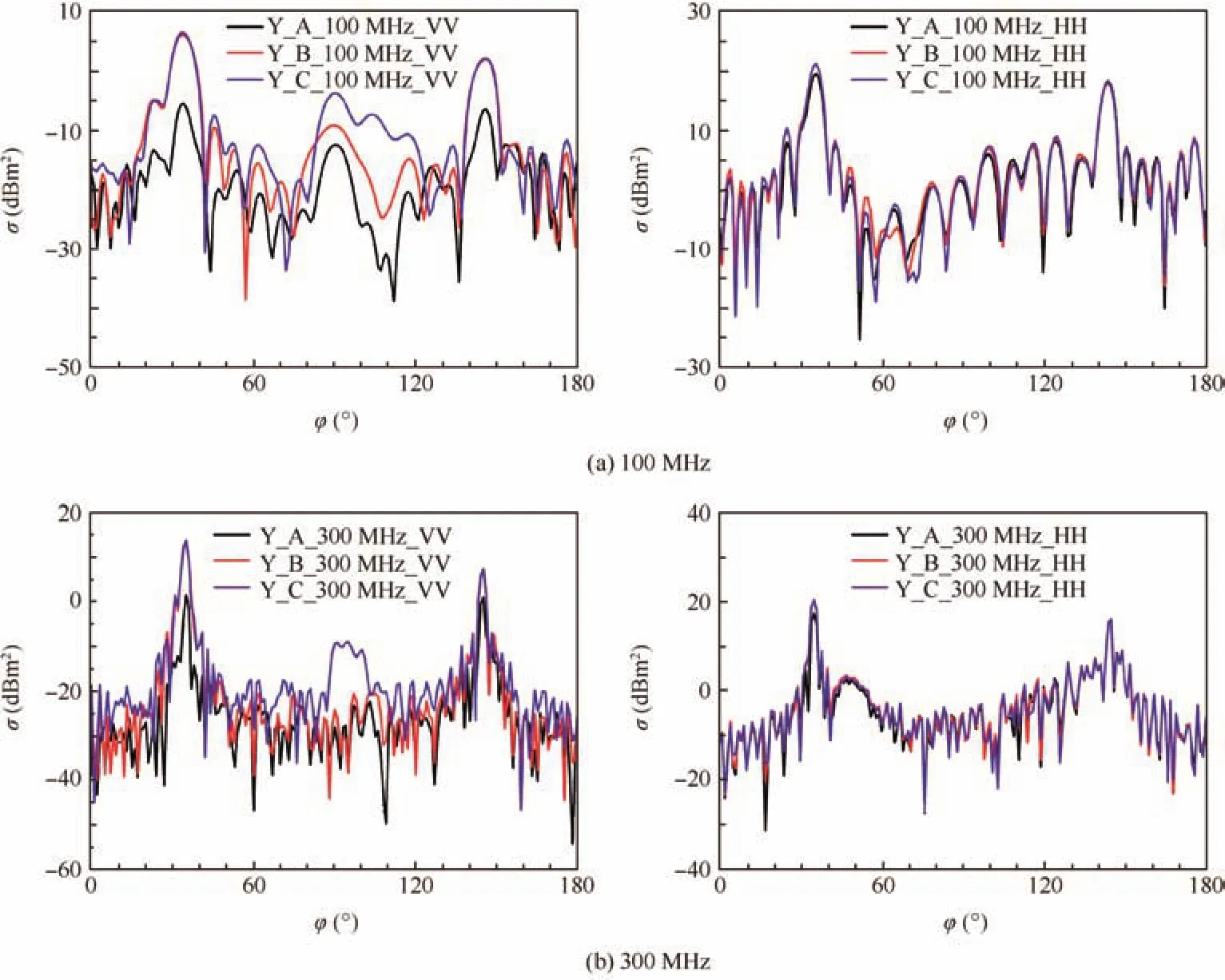
Fig.8 VV and HH RCS characteristics of flying-wing aircraft(100–300 MHz).
When the radiation frequency is less than 500 MHz,three HH RCS spikes exist on the curves at azimuth angle of 40?,75?,and 140?,which correspond to the three characteristic swept angles.Due to the short length,the wing side edge will not produce RCS spikes even in proximal front irradiation.After the radiation frequency increases up to 500 MHz,the ratio between the length of the wing side edge and the incident wavelength gets greater,and the RCS spike caused by the wing side edge appears and the spike value increases with the frequency.The fluctuation of the RCS curve increases with the radiation frequency.For the 100 MHz radiation frequency,the RCS values have little fluctuation and stay at the level of 5 dBsm2around.As the radiation frequency increases up to 300 MHz,the circumferential RCS value is not influenced by the radiation frequency significantly,and the fluctuated level is about 10 dB.
Compared to the other two models,there is a weaker RCS spike at the azimuth angle of 90?for the X_C model when the radiation frequency is less than 500 MHz.According to the geometrical model,this RCS spike is produced by the side face of the inlet,while the blocked front face of the inlet has not produced any spike.As can be seen in Fig.1,the obliquity angle of the inlet front face is 45?,23.35?larger than that of the side face.We can induce that the larger obliquity angle is the reason why no spike is produced at the position of the forward of the aircraft inlet.
4.2.RCS characteristics of flying-wing configuration concept
Figures.8 and 9 shows the VV and HH RCS characteristics of the flying-wing concept.For both VV polarization and HH polarization,RCS spikes are located at azimuth 35?and 145?positions.These spikes are mainly caused by the leading and trailing edges of the sweep wing.
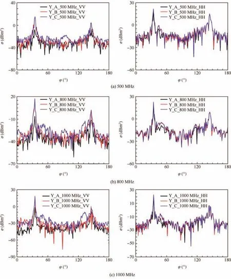
Fig.9 VV and HH RCS characteristics of flying-wing aircraft(500–1000 MHz).
For the VV polarization characteristic,the width of the RCS spike has little change as the surface distribution gradually changes from the Y_A model to the Y_C model.The spike value for Y_B is significantly larger than that of Y_A,and the difference increases when the radiation frequency increases,while the spike heights of Y_B and Y_C are almost invariant.Caused by the coupling of the outer wing tip section and the inboard surface,the three models of the Y concept all have a vertical RCS spike at the azimuth angle of 90?,and the spike width increases in turn from the Y_A model to the Y_C model.The RCS spike disappears as the radiation frequency increases to a certain value.From the Y_A model to the Y_C model,the VV RCS at the non-spike region has a downtrend as the radiation frequency increases,but the decreased amplitude becomes smaller in turn.
When the radiation frequency exceeds 100 MHz,the widths of the two spikes are invariant.As the radiation frequency increases,the amplitude of the RCS spike located at the azimuth angle of 35℃hanges a little,while the spike value at the azimuth angle of 145?decreases by about 6 dB after the radiation frequency increases up to 500 MHz.In the nonspike regions,the horizontal RCS curves all have a downtrend when the radiation frequency increases.The HH polarization scattering RCS curve amplitudes and trends for the Y_A,Y_B,and Y_C models are almost the same everywhere.In this frequency range,the spanwise cross section has little influence on HH polarization characteristics.
5.Conclusions
In the present study,the influence of aircraft surface distribution on the stealth performance at radiation frequencies between 100 MHz and 1000 MHz has been investigated through the MLFMA numerical simulation.The conclusions are summarized as follows:
(1)For the wing fuselage blended concept,the VV RCS of this frequency range is higher than the HH RCS in most cases,while the RCS curves for the flying-wing aircraft concept are just the opposite.
(2)As the frequency increases,radar scattering tends to optical scattering and the directivity gradually strengthens.The RCS levels of HH and VV both decrease with the frequency increasing,but the HH RCS has a faster downward trend.
(3)The surface distribution has little influence on RCS characteristics with HH polarization.On the contrary,it has a significant impact on RCS characteristics with VV polarization,and the amplitude of the VV RCS increases with the spanwise cross section thickness.
(4)The RCS spikes caused by the aircraft inlet are decided by the inlet surface obliquity angle.The aircraft inlet forward and lateral surface design needs emphatic consideration.
1.Ruan YZ.Radar cross section and stealth technology.Beijing:National Defense Industry Press;1998.p.11–2[Chinese].
2.Whitford R.Designing for stealth in fighter aircraft(stealth from the aircraft designer’s viewpoint).Warrendale(PA):SAE International;1996.Report No.:SAE Technical Paper 965540.
3.Paterson J.Overview of low observable technology and its effects on combat aircraft survivability.J Aircraft1999;36(2):380–8.
4.Yue KZ,Jia ZH,Ji JZ,Su M.Numerical simulation on the RCS of carrier-based electronic warfare aircraft.Syst Eng Electr2014;36(5):852–8[Chinese].
5.Yue KZ,Sun C,Ji JZ.Numerical simulation on the stealth characteristics of twin-vertical-tails for fighter.J Beijing Univer Aeronau Astronau2014;40(2):160–5[Chinese].
6.Yue KZ,Tian YF,Liu H,Han W.Conceptual design and RCS property research of three-surface strike fighter.Int J Aeronaut Space Sci2014;15(3):309–19.
7.Chen SC,Yue KZ,Hu B,Guo R.Numerical simulation on the radar cross section of variable-sweep wing aircraft.J Aerosp Technol Manage2015;7(2):170–8.
8.Yue KZ,Gao Y,Li GX,Yu DZ.Conceptual design and RCS performance research of shipborne early warning aircraft.J Syst Eng Electron2014;25(6):968–76.
9.Chen LL,Yue KZ,Xing CF,Yu D.RCS numerical simulation of stealth modified three-surface aircraft.Int J Aeronaut Space Sci2016;17(1):101–8.
10.Li Y,Huang J,Hong S,Wu Z,Liu Z.A new assessment method for the comprehensive stealth performance of penetration aircrafts.Aerosp Sci Technol2011;15(7):511–8.
11.Song JM,Lu CC,Chew WC.Multilevel fast multipole algorithm for electromagnetic scattering by large complex objects.IEEE Trans Antennas Propag1997;45(10):1488–93.
12.Knott EF.A progression of high-frequency RCS prediction techniques.Proc IEEE1985;73(2):252–64.
13.Senior T,Volakis JL.Scattering by gaps and cracks.IEEE Trans Antennas Propag1989;37(6):744–50.
14.Wang JJH.Generalized moment methods in electromagnetics.IEE Proc H1990;137(2):127–32.
15.Gao ZH,Wang ML.An efficient algorithm for calculating aircraft RCS based on the geometrical characteristics.Chin J Aeronaut2008;21(4):296–303.
16.Rao SM,Wilton DR,Glisson AW.Electromagnetic scattering by surfaces of arbitrary shape.IEEE Trans Antennas Propag1982;30(3):409–18.
17.Cui TJ,Chew WC,Chen G,Song J.Efficient MLFMA,RPFMA,and FAFFA algorithms for EM scattering by very large structures.IEEE Trans Antennas Propag2004;52(3):759–70.
18.Liu ZH,Huang PL,Wu Z,Gao X.Analysis of scattering from serrated edge plate on aircraft with MLFMA.J Beijing Univer Aeronau Astronau2008;34(5):499–502[Chinese].
19.Liu ZH,Huang PL,Gao X,Ji JZ.Multi-frequency RCS reduction characteristics of shape stealth with MLFMA with improved MMN.Chin J Aeronaut2010;23(3):327–33.
20.Song JM,Chew WC.Fast multipole method solution of three dimensional integral equation.IEEE Trans Antennas Propag1995;45(10):1528–31.
23 February 2016;revised 21 October 2016;accepted 27 November 2016
Available online 20 February 2017
*Corresponding author.
E-mail address:songlei@buaa.edu.cn(L.Song).
Peer review under responsibility of Editorial Committee of CJA.
杂志排行

CHINESE JOURNAL OF AERONAUTICS的其它文章
- Dynamics of air transport networks:A review from a complex systems perspective
- ATM performance measurement in Europe,the US and China
- Network analysis of Chinese air transport delay propagation
- Robustness analysis metrics for worldwide airport network:A comprehensive study
- Evolution of airports from a network perspective–An analytical concept
- Methods for determining unimpeded aircraft taxiing time and evaluating airport taxiing performance