A study on optimal control of the aero-propulsion system acceleration process under the supersonic state
2017-11-20SunFengyongDuYaoZhangHaibo
Sun Fengyong,Du Yao,Zhang Haibo
College of Energy and Power Engineering,Nanjing University of Aeronautics and Astronautics,Nanjing 210016,China Jiangsu Province Key Laboratory of Aerospace Power System,Nanjing 210016,China
A study on optimal control of the aero-propulsion system acceleration process under the supersonic state
Sun Fengyong,Du Yao,Zhang Haibo*
College of Energy and Power Engineering,Nanjing University of Aeronautics and Astronautics,Nanjing 210016,China Jiangsu Province Key Laboratory of Aerospace Power System,Nanjing 210016,China
Acceleration control;Inlet control design;Inlet and engine cooperative working;Optimal control
In order to solve the aero-propulsion system acceleration optimal problem,the necessity of inlet control is discussed,and a fully new aero-propulsion system acceleration process control design including the inlet,engine,and nozzle is proposed in this paper.In the proposed propulsion system control scheme,the inlet,engine,and nozzle are simultaneously adjusted through the FSQP method.In order to implement the control scheme design,an aero-propulsion system componentlevel model is built to simulate the inlet working performance and the matching problems between the inlet and engine.Meanwhile,a stabilizing inlet control scheme is designed to solve the inlet control problems.In optimal control of the aero-propulsion system acceleration process,the inlet is an emphasized control unit in the optimal acceleration control system.Two inlet control patterns are discussed in the simulation.The simulation results prove that by taking the inlet ramp angle as an active control variable instead of being modulated passively,acceleration performance could be obviously enhanced.Acceleration objectives could be obtained with a faster acceleration time by 5%.
1.Introduction
Acceleration performance is one of the most important aircraft operation qualities.1,2During the acceleration process,the integral aero-propulsion system including the inlet,engine,and nozzle is the primary power unit to provide an aircraft with sufficient thrust to implement the acceleration process.Especially under the supersonic state,the inlet and engine are both crucial components of the acceleration parts,accompanying seriously coupling dynamics.As is well known,compressor surge prevention is the mainly focused factor in theengine acceleration design.Meanwhile,engine inlet distortion could shrink the surge margin.3Usually,engine inlet distortion is generated under the inlet supercritical state,and the engine acceleration process is always accompanied with inlet distortion.Therefore,it is meaningful to take the whole aero-propulsion system including the inlet and engine into consideration in the acceleration process control.
The inlet shows a big different performance under the supersonic state compared to that under the subsonic state.Under the supersonic state,a mismatched inlet could badly affect the engine installed performance.Moreover,a fixedgeometry inlet is restricted in the flight of a wide-range Mach number.On the inlet off-design point,air mass flows that the inlet provides and the engine demands might not couple with each other.Consequently,the inlet working state would depart from the critical state.Furthermore,inlet spillage airflow or inlet outlet distortion comes into being under the subcritical or supercritical state.Variety of airflow in the engine acceleration process requests the inlet to provide balanced airflow.However,a variable-geometry inlet could relieve that damage to the cooperative working conditions between the inlet and engine.Modulation of the inlet throat area by an inlet ramp angle could keep the inlet working near the critical state and prevent inlet outlet distortion and inlet surge.4–7
Engine acceleration design always focuses on the safety and response time when referring to the acceleration performance index.The compressor surge margin,turbine inlet temperature,and fuel-air ratio are also key factors to engine accelerating safety.Engine inlet distortion is the main external disturbance to the compressor surge margin,which could lessen the surge margin and even induce an engine surge.8,9On the other hand,varieties of engine working states might bring the inlet into an unsteady working state,in which the distortion comes into being at the inlet outlet.Therefore,the coupling working conditions between the engine and inlet could guarantee the safety of the inlet working state and the engine compressor surge margin.
Currently available propulsion system acceleration process control schemes could be classified into two categories,passive control and active control.The present work on the aeropropulsion system acceleration process control focuses on the engine accelerating road and its optimization.This would easily neglect the inlet impacts to the engine.Especially under the supersonic state,the engine is greatly influenced by the inlet air mass flow quality.However,in this paper,the matching problems between the inlet and engine are fully considered and analyzed.The inlet and engine cooperative working principals are analyzed in both the fluent and pressure fields.Furthermore,in the acceleration process control design,an inlet modulated variable is added to the fuel flow rate and nozzle throttle area as one of the main control variables.
In order to study the optimal control of the aero-propulsion system acceleration process,an integral component-level model including the inlet and engine is built.Based on the model,a new inlet control scheme accompanying the initial acceleration schedule is proposed.In addition,this paper always advances a new propulsion system optimal acceleration schedule by regulating the inlet,engine,and nozzle at the same time,which means that a corrected inlet ramp angle is added to the fuel mass flow and nozzle throat area as control variables in the acceleration process.All the acceleration optimal control designs and simulations are conducted on an aero-propulsion system including a supersonic inlet which is designed at a 2.5 Mach number and a turbofan engine.
2.Inlet regulation necessity in engine acceleration process
As is illustrated in Fig.1,a special acceleration schedule is settled in the passive control management,and particular control logics are used in the engine active control.10Neither of the two control managements has taken the inlet coupling impacts into account.However,the inlet plays a non-ignorable role in the acceleration process which would be fully discussed in the second part.11
While the coupling factors between the inlet and engine involve the airflow field,pressure field,temperature field,and other physical aspects,the stress here is on the air mass flow and total pressure equilibrium in the integral propulsion system component-level modeling.More modeling technical details are described in Ref.12
Apparently,the purpose of the inlet is intended to support the engine steady and sufficient airflow.Under the supersonic state,the inlet outlet pressure is determined by the engine air stream.Meanwhile,the inlet terminal shock is also affected by the inlet outlet pressure.With the inlet and engine cooperative working principals,the inlet air mass flow should be equal to the engine mass flow.On the assumption that the inlet has a fixed geometry,the equal air mass flow equilibrium could be described as
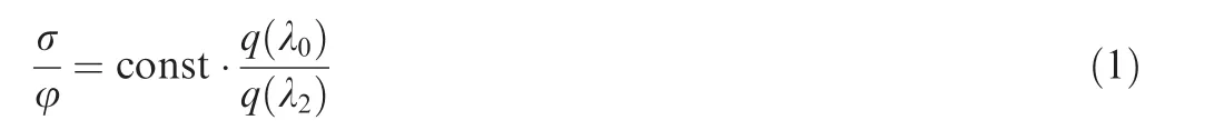

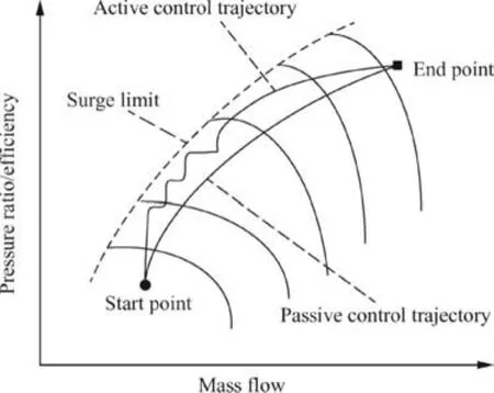
Fig.1 Trajectory of the acceleration process in passive control and active control.
On the assumption that the engine and inlet are in a good cooperative working state and matched well to each other,then the co-working point ‘I” is in the critical region.In the engine acceleration process,the requirement for airflow increases would be beyond what is required for critical operation,and the inlet co-working point moves into the supercrit-ical region if the inlet ramp is fixed on the same angle.The co-working point will shift to point‘II”.Meanwhile,inlet output distortion appears and will enlarge with the departure of the critical point.Inlet outlet distortion deteriorates the engine compressor working conditions.The worse situation is that the compressor surge margin will be further compressed in the acceleration process.13
Once the inlet geometry such as the inlet ramp angle is variablein the acceleration process,the inletand engine co-working point could shift from ‘I” to ‘III” instead of‘II”.Then the engine and inlet would constantly keep at the optimal working conditions in the acceleration process.Meanwhile,it is worth noting that the engine and inlet co-working point is also acceptable when the point is in the subcritical region and is very close to the critical region.
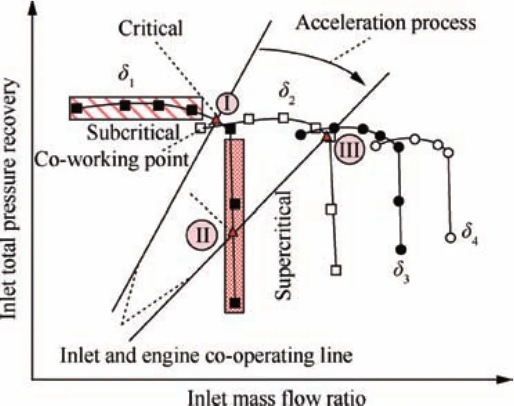
Fig.2 Propulsion system acceleration process diagram.
3.Inlet acceleration control design
In inlet steady control,the engine fan corrected rotor speed is always set as the feed-back signal to confirm the inlet ramp angle order.An airflow total pressure sensor and a velocity sensor could also be arranged inside the inlet.In the engine acceleration process,however,airflow distortion always appears in the outlet inlet.Therefore,symmetric pressure sensors should be arranged on the circular side of the inlet.This will highly increase the aircraft weight,which is inconsistent to the aircraft design.On the other hand,the engine is in a dynamic state,so the engine fan speed could not exactly reflect the inlet ramp angle.

A PI controller is applied in the inlet ramp angle control application,and the control structure is shown in Fig.4.Based on the propulsion system measurable parameters and pilot commands,the inlet ramp angle mapping module will calculate an optimal inlet ramp angle.With the comparison to the present inlet ramp angle,the PI controller will rapidly control or modulate the inlet ramp to the right ramp angle.
4.Aero-propulsion system acceleration optimal control design
4.1.Principles of acceleration optimal control design
As is introduced in Introduction,engine acceleration process design intends to make out an acceleration schedule for the aero-propulsion system.Acceleration time is a significant measurable indicator,which is defined as
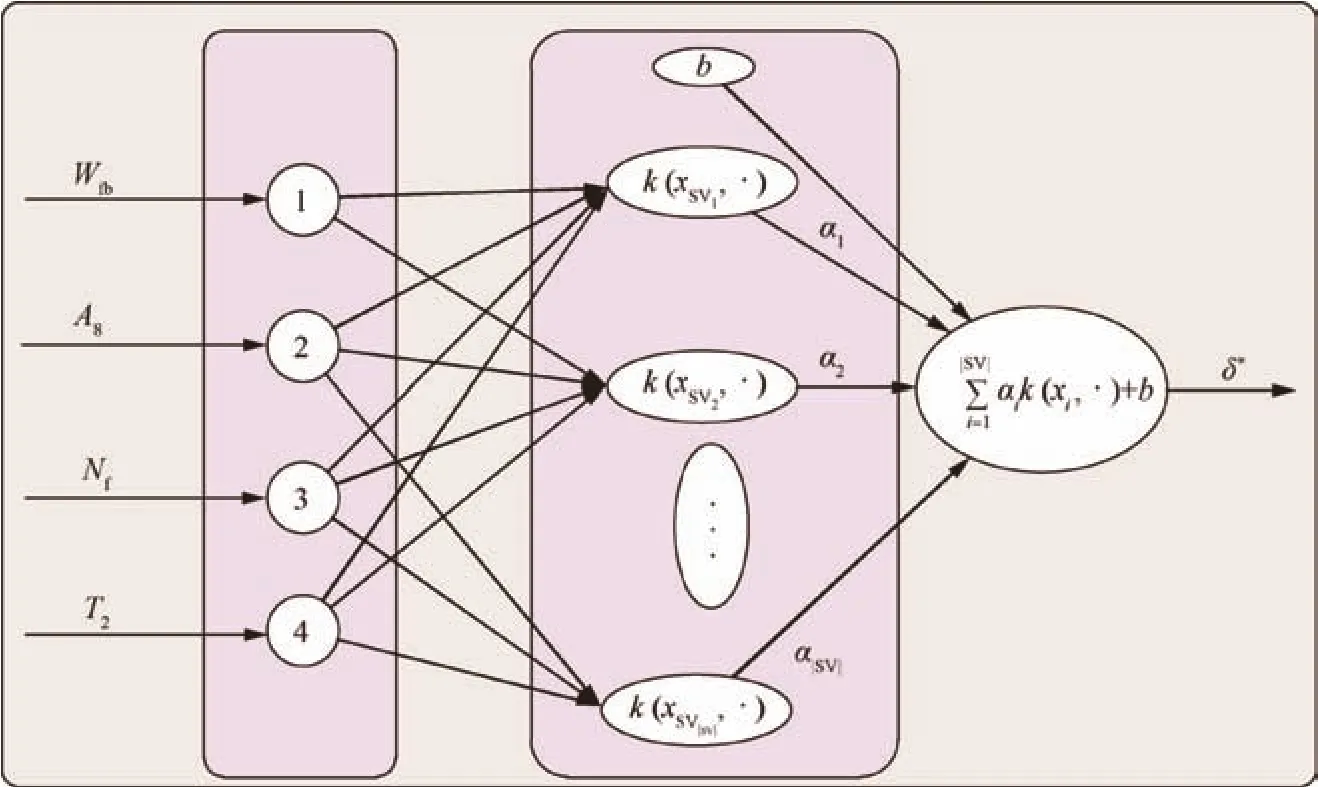
Fig.3 Configuration of the RR-LSSVR estimator.
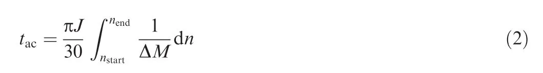
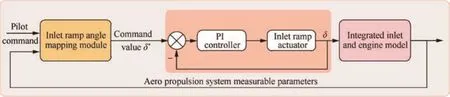
Fig.4 Control structure of the inlet ramp angle.
whereJis the engine rotor rotary inertia,DMis the engine rotor residual torque,nstartis the initial engine rotor speed,andnendis the engine objective rotor speed.
The intention of the acceleration process is to increase the engine installed thrust(Fin)as soon as possible.The engine installed thrust augmentation is mainly restricted with the engine airflow,which could be presented by the engine fan speed to some degrees.Consequently,the engine installed thrust and fan rotor speed are set to be optimal objectives.Therefore,the objective function could be expressed as
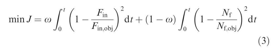
where x is the weight of the optimal objective,and subscript‘obj”means the objective value at the acceleration ending point.
As the engine acceleration is a dynamic process,a constant objective function should be discretized in the optimal control design,so Eq.(3)could be transformed as
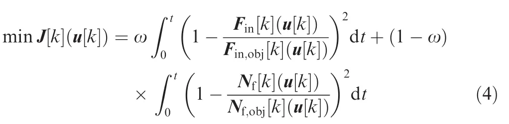
where u[k]is the control variable vector at stepk.
Because the acceleration optimal control scheme proposed in this paper is an entire propulsion system control design,inlet,engine,and nozzle constraint parameters should be fully satisfied in the optimal control process.The constraints are
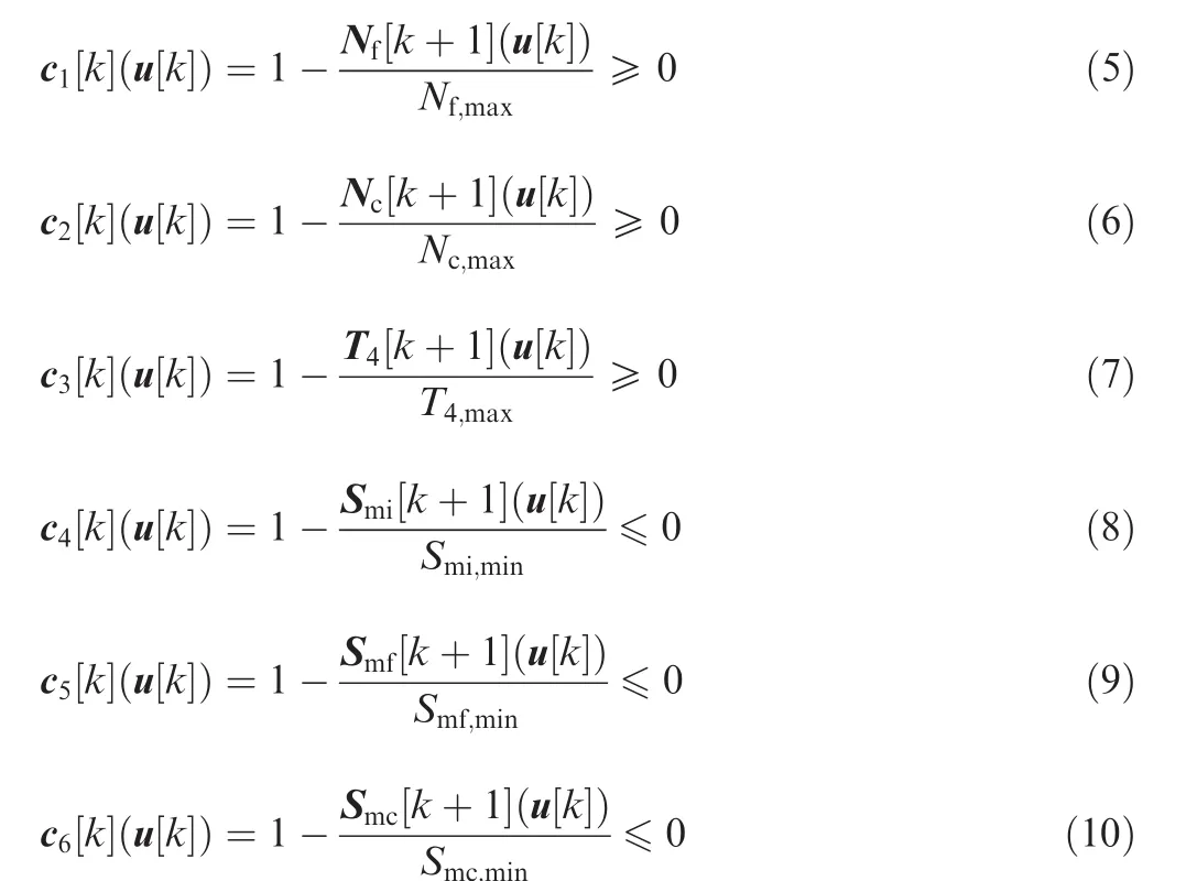

whereNcis the engine compressor rotor speed,T4is the inlet temperature of the high-pressure turbine,Smfis the fan surge margin,Smcis the compressor surge margin,andFaris the fuel-air ratio.Smimeans the inlet surge margin,and it can be calculated by
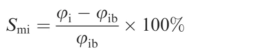
Furthermore,the optimal control design is also restricted by the engine control actuator geometry limit and the velocity restricts of control variables.
4.2.Optimal algorithm of acceleration control
The optimizing algorithm used here is feasible sequence quadratic programming(FSQP),whose general method is stated as follows.
For a general problem,
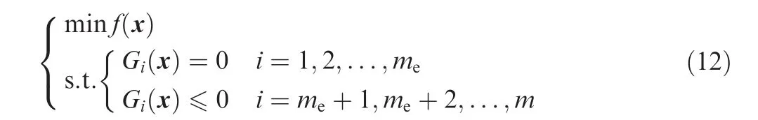
The principal idea is to formulate a QP sub-problem based on the quadratic approximation of the Lagrangian function as
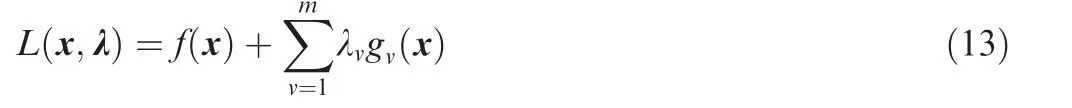
Assuming that constraints have been expressed as inequality constraints,the QP sub-problem could be obtained by linearizing nonlinear constraints as
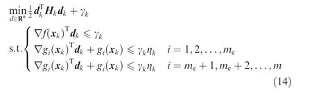
The solution of the QP sub-problem could form a new iterate,i.e.,


5.Aero-propulsion system acceleration control simulation
In order to verify the effectiveness of the inlet acceleration control design,simulation tests are conducted through online simulation.A fully duplicated component-level model from the original aero-propulsion model is taken as the ‘onboard model”.The modelling steady relative errors of the onboard model are less than 1%compared to the real engine parameters as validated.12The acceleration process optimized objectives are initialized by the pilot commands,and the constrained parameters in the simulation are all obtained from the ‘onboard model”.Moreover,the simulating software environment is within the VS2010 in Win 7 64bit system and the hardware parameters of the computer is i3(3.30 GHz)CPU and 4 GB memory.
The acceleration process optimized control scheme structure is shown in Fig.5.Once the acceleration begins,acceleration optimized commands would reach the optimized module.In every control step,the optimized control system will calculate optimized acceleration control commands,and then the optimized control commandWfb*is taken as the corrected current limit,which is used to correct the original acceleration fuel feeding plan online.Meanwhile,the nozzle throttle areaA8is taken as an open-loop control variable and the corrected inlet ramp angle is added to the original inlet ramp angle as the new control variable value.The optimized control system will keep on calculating the optimized acceleration road until the optimized objective is reached.
The simulation firstly proceeds as passive control management,which means that in the acceleration optimal control process,the inlet ramp angle is operated passively instead of being taken as an active control variable.In this acceleration optimal control mode,the fuel mass flow ratio and nozzle throat area are the control variables,and in the following simulation analysis,this mode will be called ‘inlet passive control”for short.Then,the inlet ramp angle is amended as the optimal control variable along with the fuel mass flow and nozzle throat area.In this mode,the inlet ramp angle,fuel mass flow ratio,and nozzle throat area are all taken as control variables.Analogously,this mode will be called ‘inlet active control”for short.Both of the optimal control modes have the same initial starting point and terminal objectives.
The simulations are conducted at the same flight condition,H=10 km andMa=1.6.Both of the two control methods finished the acceleration process and accomplished the preset objectives,as shown in Fig.6.Moreover,the ‘inlet active control”mode has a faster acceleration time,which is more obvious referring to the engine installed thrust and is beneficial to the acceleration process.

Fig.6 Finand Nfin the acceleration process.
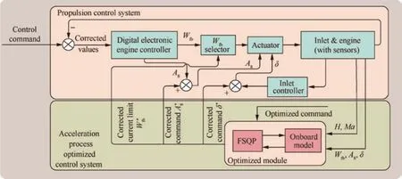
Fig.5 Control structure of the aero-propulsion system acceleration process.
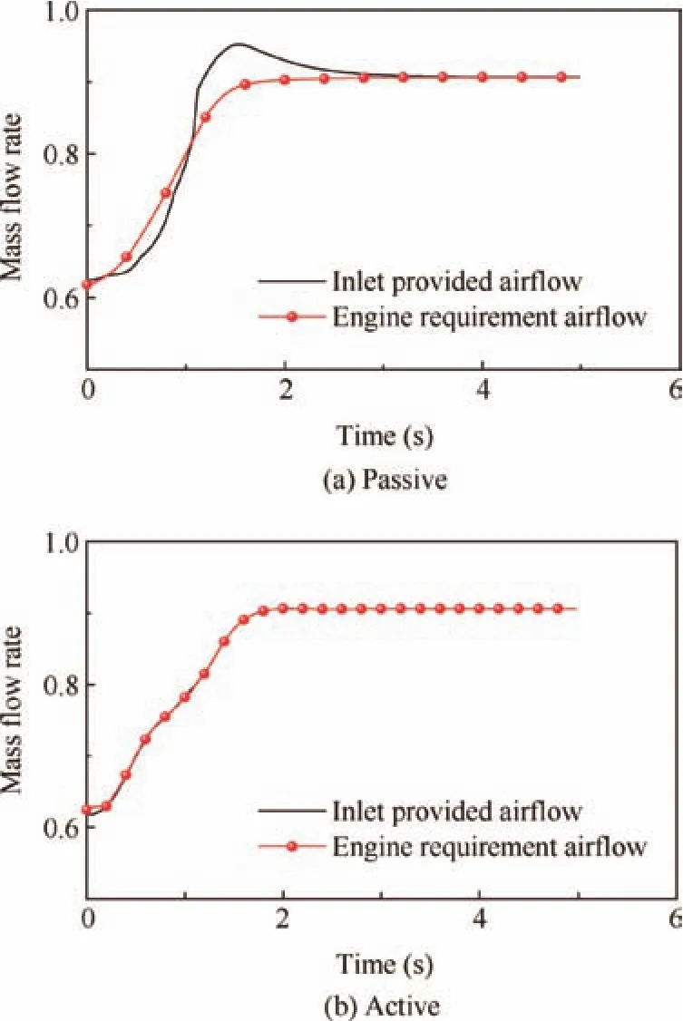
Fig.7 Air mass flow in the inlet passive control mode and inlet active control mode.
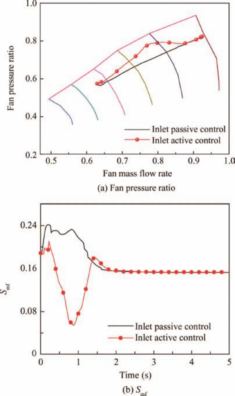
Fig.8 Fan pressure ratio and Smfin the acceleration process.
The improved acceleration performance in the ‘inlet active control” mode compared to that in the ‘inlet passive control”mode largely bene fits from a well matched engine and inlet working conditions,as shown in Fig.7.The inlet acceleration control scheme in this paper is approximately satis fied for the engine air flow requirements.Illustrated from Fig.7(a),the air mass flow that the inlet provided is closely consistent with the engine air mass flow requirement.However,a nearly perfect matched engine and inlet co-working state is obtained if the inlet ramp angle is considered as an active control variable.As shown in Fig.7(b),the inlet air mass flow replicates the airflow of engine air flow requirements.
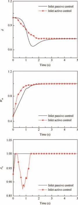
Fig.9 Inlet ramp angle,fuel flow rate and nozzle throat area in the acceleration process.
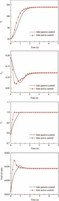
Fig.10 Nc,Smc,T4and fuel-air ratio in the acceleration process.
As shown in Fig.8(a),the ‘inlet active control” mode exploits the engine for more potential performance.The acceleration line in the fan pressure ratio versus the mass flow rate map is closer to the surge limit.Even thoughSmfin the ‘inlet active control” mode is smaller than that in the ‘inlet passive control”mode,the fan surge margin is still in a safe region,as shown in Fig.8(b).
The inlet ramp angles in the two optimal control modes vary differently.As an active control variable,the inlet ramp angle plays a more vital role in modulating the air mass flow between the engine and inlet.The optimal control operating variables are presented in Fig.9.
Other constraint parameters also meet the requirements.The tendencies of the propulsion system state parameters in the acceleration process are constantly in the prescribed regions,as shown in Fig.10.
6.Conclusions
This paper concentrates on the integral aero-propulsion system acceleration optimal control.According to the analysis of engine and inlet co-working principles,it could be concluded that inlet modulation is necessary in the propulsion system acceleration process.The inlet ramp angle could be taken as the inlet control variable,and inlet ramp angle modulation could keep the engine and inlet constantly in a well-matched airflow condition.Furthermore,inlet modulation plays an important role in improving engine inlet distortion.A new inlet acceleration control design is proposed in this paper.Simulation results prove that taking the inlet ramp angle as an input optimal acceleration control variable instead of being modulated passively,acceleration performance could be obviously enhanced.The acceleration process could be completed with a faster acceleration time.
Acknowledgements
This study was co-supported by the Fundamental Research Funds for the Central Universities(No:NZ2016103)and the NationalNaturalScienceFoundation ofChina (No:51576096).
1.Heymsfield E,Hale WM,Halsey TL.Aircraft response in an airfield arrestor system during an overrun.J Transp Eng2012;138(3):284–92.
2.Pashilkar A,Ismail S,Ayyagari R,Sundararajan N.Design of a nonlinear dynamic inversion controller for trajectory following and maneuvering for fixed wing aircraft.2013 IEEE symposium on computational intelligence for security and defense applications(CISDA);2013 Apr 16–19;Piscataway,NJ:IEEE Press;2013.p.64–71.
3.Meerts C,Steelant J.Air intake design for the acceleration propulsion unit of the LAPCAT-MR2 hypersonic aircraft.5th Europeanconferenceforaeronauticsandspacesciences(EUCASS);Munich.
4.Williams JG,Steenken WG,Yuhas AJ.Estimating engine airflow in gas-turbine powered aircraft with clean and distorted inlet flows.Edwards(CA):Dryden Flight Research Center;1996 Sep.Report No.:NASA-CR-198052.
5.Kopasakis G,Connolly JW,Seidel J.Propulsion system dynamic modeling ofthe NASA supersonic conceptvehicle for AeroPropulsoServoElasticity.Reston:AIAA;2014.Report No.:AIAA-2014-3684.
6.Kopasakis G,Connolly JW,Kratz J.Quasi one-dimensional unsteady modeling of external compression supersonic inlets.48th AIAA/ASME/SAE/ASEE joint propulsion conference&exhibit;2012 July 30–Aug 1;Atlanta,GA.2012.p.4147.
7.Connolly J,Kopasakis G,Paxson D,Stuber E,Woolwine K.Nonlinear dynamic modeling and controls development for supersonic propulsion system research.Reston:AIAA;2011.Report No.:AIAA-2011-5635.
8.Li J.Optimization of aero engine acceleration control in combat state based on genetic algorithms.Int J Turbo Jet Eng2012;29(1):29–36.
9.Huang W,Huang X.Adaptive acceleration control for aeroengine based on active anti-surge control.Measure Control Technol2013;32(4):61–9[Chinese].
10.Dhingra M.Compressor stability management[dissertation].Atlanta,GA:Georgia Institute of Technology;2006.
11.Dhingra M,Neumeier Y,Prasad J.Active compressor stability management and impact on engine operability.Reston:AIAA;2004.Report No.:AIAA-2004-3984.
12.Sun F,Zhang H,Ye Z.Integrated control for supersonic inlet/engine.J Aerospace Power2014;29(10):2279–87[Chinese].
13.Mattingly JD.Aircraft engine design.Reston:AIAA;2002.p.189–229.
14.Zhao Y,Sun J.Recursive reduced least squares support vector regression.Pattern Recogn2009;42(5):837–42.
15.Cherkassky V,Ma Y.Practical selection of SVM parameters and noise estimation for SVM regression.Neural Networks2004;17(1):113–26.
16.Lawrence CT,Tits AL.A computationally efficient feasible sequential quadratic programming algorithm.Siam J Optimiz2000;11(4):1092–118.
17.Zhu Z.A simple feasible SQP algorithm for inequality constrained optimization.NonlinearAnalRealWorldAppl2006;182(2):987–98.
21 February 2016;revised 4 August 2016;accepted 7 September 2016
Available online 14 February 2017
*Corresponding author at:College of Energy and Power Engineering,Nanjing University of Aeronautics and Astronautics,Nanjing 210016,China.
E-mail address:zh_zhhb@126.com(H.Zhang).
Peer review under responsibility of Editorial Committee of CJA.
杂志排行

CHINESE JOURNAL OF AERONAUTICS的其它文章
- Dynamics of air transport networks:A review from a complex systems perspective
- ATM performance measurement in Europe,the US and China
- Network analysis of Chinese air transport delay propagation
- Robustness analysis metrics for worldwide airport network:A comprehensive study
- Evolution of airports from a network perspective–An analytical concept
- Methods for determining unimpeded aircraft taxiing time and evaluating airport taxiing performance