Static aeroelastic analysis including geometric nonlinearities based on reduced order model
2017-11-20XieChangchuanAnChaoLiuYiYangChao
Xie Changchuan,An Chao,Liu Yi,Yang Chao
School of Aeronautic Science and Engineering,Beihang University,Beijing 100083,China
Static aeroelastic analysis including geometric nonlinearities based on reduced order model
Xie Changchuan*,An Chao,Liu Yi,Yang Chao
School of Aeronautic Science and Engineering,Beihang University,Beijing 100083,China
Aeroelasticity;Finite element method;Geometric nonlinearity;Reduced order models;Trims
This paper describes a method proposed for modeling large deflection of aircraft in nonlinear aeroelastic analysis by developing reduced order model(ROM).The method is applied for solving the static aeroelastic and static aeroelastic trim problems of flexible aircraft containing geometric nonlinearities;meanwhile,the non-planar effects of aerodynamics and follower force effect have been considered.ROMs are computational inexpensive mathematical representations compared to traditional nonlinear finite element method(FEM)especially in aeroelastic solutions.The approach for structure modeling presented here is on the basis of combined modal/finite element(MFE)method that characterizes the stiffness nonlinearities and we apply that structure modeling method as ROM to aeroelastic analysis.Moreover,the non-planar aerodynamic force is computed by the non-planar vortex lattice method(VLM).Structure and aerodynamics can be coupled with the surface spline method.The results show that both of the static aeroelastic analysis and trim analysis of aircraft based on structure ROM can achieve a good agreement compared to analysis based on the FEM and experimental result.
1.Introduction
The requirement of the research of very flexible unmanned aerial vehicle(UAV)is increasing rapidly.As the representative of the very flexible UAV,high-altitude long-endurance(HALE)aircrafts usually attract extensive attention.Because of its light weight and large flexibility,the wing of HALE will produce large deformation during the flight and structural stiffness has the behavior in a nonlinear manner owing to the change of geometric stiffness.Meanwhile,significant elastic deformation of wing will bring significant changes in aerodynamics configuration and stiffness characteristics of the airplane,which causes the aeroelastic problem of large flexible aircraft.The traditional linear method of static aeroelastic analysis does not take into account the effects of non-planar aerodynamic or structural geometric nonlinearity.For the design requirement of HALE,Patil and Hodges proposed the concept of geometrical nonlinear aeroelasticity of fixed wing in 1999.1,2Over the past several years,lots of research with diverse content of geometrically nonlinear aeroelastic problem where large flexible HALE as the main object has been carried out.3–9Patil and Hodges used a geometrically-exact beam theory to study thegeometric nonlinearities effects in static or dynamic aeroelastic analysis with structure like large-aspect-ratio wing.1,5,6Palacios and Cesnik solved nonlinear static aeroelastic responses with a CFD/CSD coupled method.10Xie used generalized strips theory and structure nonlinear finite element method(FEM)to analyze the aeroelastic characteristics of a flexible wing with large deformation.Moreover,the linearized method was used to predict flutter characteristic of the flexible wing in the research.11,12Howcroft et al.discussed five aeroelastic modeling methods applied to the aeroelastic analysis including geometric nonlinearities in recent research.Predictions of static aeroelastic equilibria from five modeling method were compared.Discussions of aerodynamic modeling choices,orientation of aeroforces and drag effect they made in the paper have important influence in the related research.13
Trim analysis is the significant part in the aircraft design progress.When structure undergoes large deformation,the non-planar aerodynamic effect will emerge and the large deformation will impact on structural stiffness.The linear aeroelastic method based on the assumption thatstructural deformation is infinitesimal fails to analyze such aeroelastic characteristics of very flexible aircraft.Patil and Zhang et al.developed a method by combing the ONERA aerodynamics model and the nonlinear beam.12,14Wang et al.proposed a method combining the nonlinear FEM and nonplanar vortex lattice method(VLM)by iterative progress in aeroelastic trim analysis including geometrical nonlinearity.The result of longitudinal trim analysis is presented including the linear method and nonlinear method proposed.15,16The linear method in that research is mainly based on MSC.Flightloads.
Nonlinear FEM is used to calculate the stiffness of model and displacement under aerodynamics in aeroelastic analysis usually in consideration of geometric nonlinearities.This simulation of geometrical nonlinearity requires expensive computation(Newton Raphson method).There should be large amount of freedom in solving aeroelastic problem including geometrical nonlinearity and coupling of structure and dynamics requires lots of iterative progress,so that application of nonlinear FEM in aeroelastic problem including geometrical nonlinearity is limited severely.Compared to FEM,reduced order model(ROM)can reduce the scale of the problem and can analyze the characteristics of large flexible aircraft geometrics nonlinearity easily.It shows us computational inexpensive mathematical representation of structure analysis in nonlinear aeroelastic problem and offers the potential for nearly realtime analysis.Demasi and Palacios reconducted the function of load step with structural tangent modes via procedure of proper orthogonal decomposition(POD)to reduct freedom of structure with planar and non-planar structural configurations.17Structural geometrical nonlinearities were considered and aerodynamic nonlinearities were not considered in their research for aeroelastic analysis.Intrinsic beam theory is a useful methodology for structural analysis in nonlinear aeroelastic problem.Reducing aircraft configuration to intrinsic beam has been a usual reduced order method in nonlinear aeroelastic analysis.18,19Wang et al.described reduced-modal methodology for modeling nonlinear aeroservoelastic response of the flexible aircraft and characterize structural geometrical nonlinearities through a modal intrinsic form of structural equation.20They used force and velocity modes in the description of intrinsic beam calculated by displacement modes.Guyan reduction is used to obtain displacement modes from complex model.Though intrinsic beam description considers geometrical nonlinearities of structural well,Guyan reduction carried out by linear equation of motion causes some loss of nonlinear characteristics,which is the defect of most equivalent beam/shell theory.It is worth noting that there have been some approaches investigated by utilizing commercial FEM software package to obtain structure ROMs.In particular McE-wan et al.performed the modal/FE(MFE)method by static analysis with numbers of specified static load cases.21Displacements obtained by static analysis were then curve fitted using regression analysis for the purpose of describing nonlinear stiffness values which reflect structural nonlinear characteristics in structural motion equations.Harmin and Cooper implied the MFE approach for modeling the geometric nonlinearity of a large-aspect-ratio wing model.Aeroelastic analysis has been performed utilizing the structural model and the rational function approximation(RFA)of doublet lattice aerodynamics using Roger method when the nonlinear ROM has been obtained.22This approach can be used to predict the static deflection,gust response and limit cycle oscillation.Their process has some limitation.They did not consider the follower force effect,lateral displacement and non-planar of aerodynamics loads under the aircraft configuration with large deformation in aeroelastic solutions based on ROM.Lateral displacement will reduce the effect of lifting surface.
Research in this paper aims to solve static aeroelastic problem primarily.Large deformation of flexible aircraft changes the aerodynamics loads and structural dynamic features.All these may have a big influence on dynamic stability characteristics or response analysis.Solving static aeroelastic nonlinear equilibrium state reveals the change of structure dynamic features.It is the basis of solving dynamic aeroelastic problem including geometric nonlinearity.Meanwhile,calculation of aerodynamic derivatives and static/dynamic stability of flexible aircraft requires confirmation of deformed configuring of aircraft.It is obvious that static aeroelastic trim analysis should be the basis of aerodynamic derivatives calculation and research of aircraft stability.We improve the MFE approach as ROM implies to solve aeroelastic problems,to make it more fully reflect the influence of large deformation of wing under load in the analysis of aeroelasticity.The prescribed load cases with follower force and the corresponding displacements obtained from the nonlinear FEM static analysis are transformed into modal coordinates by the modal transformation of underlying linear system where more useful modes have been applied to participating in modeling.We use a regression analysis to curve fit the sets of test load and nonlinear displacement maps for the sake of finding the unknown nonlinear stiffness coefficient.When structural ROM is obtained,it is introduced to solve structure displacement considering geometric nonlinearity.The non-planar aerodynamic loads are computed by a non-planar VLM.22Then,surface spline interpolations approach is performed for structure/aerodynamics coupling.23After that,we solve the static aeroelastic displacement with iterative method.Moreover,the static aeroelastic analysis of wing including geometric nonlinearity is carried out by ROM structure solutions,nonlinear FEM solutions and linear solutions.It is necessary to compare the results obtained from the three methods and experimental results.Then,we apply the approach to a flexible aircraft model to solve the nonlinear trim problem by iterative method.Equilibrium equations in trim analysis are established on deformed aircraft with rigid motion.Moreover,the trim analysis of a flexible aircraft is carried out by ROM structure solutions,nonlinearFEM solutionsand linearsolutions.Results obtained by the three approaches are also in comparison.
2.Formulation
2.1.Geometric nonlinear elasticity
Under heavy aerodynamic loads,the large aspect ratio wing of very flexible aircraft produces nonlinear large deformation.Especially materials of structure satisfy the linear elastic theory as ever.In this case,it is necessary to include second order terms of the deflection derivative into the geometric nonlinear elasticity equations.
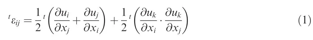
We use Updated Lagrange Formulation of nonlinear FEM to compute the structure deformation,and that is the basis of the establishment of ROM.The Green-Lagrangian strain tensor at timetin nonlinear FEM analysis has an expression as follows:
Hereuiis displacement andxjcoordinate.The nominal stress tensorSjihas the relationship as follows:

Heretnjis the normal vector of element ds,and dTjis the corresponding surface force.The relationship of strain and displacement is performed as follows due to the materials of structure obeying linear relation:

HereDijklis the elastic tensor.We use incremental FEM to calculate the geometric nonlinear deflection.It is noteworthy that follower force effect should be considered in geometric nonlinear aeroelastic analysis.The strain tensor eijshould be decomposed into two parts:a linear parteijand a nonlinear partnij:

The stress tensor should also be decomposed in two parts.Tensortsijis the incremental stress at timet,which requires to be calculated at each time step.tSijis the equilibrium stress.

The relationship of strain and deflection considering numbers of shape functions is performed as

wheretBLandtBNLare the linear and nonlinear shape functions of the element at time stept,respectively,anduis the corresponding generalized coordinate.
The element governing equation can be obtained when substituting those shape functions into Eq.(6)as

2.2.Nonlinear ROM
2.2.1.Nonlinear structure equation
Static structural equation only in the direction of transverse has the form in physical coordinates:

The temporal and spatial components of deflection can be separated by translating the equation into modal space with relationship between modal amplitudes and transverse deflection as:

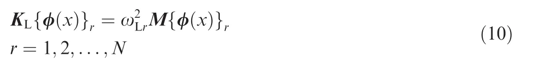


When completing the modal transformation,motion equation in modal coordinates can be

Here,ELrepresents the modal stiffness matrix and fðtÞ represents the modal force vector.It is worth noting that all of the matrices in Eq.(12)are diagonal expect the nonlinear stiffness matrix ENL.Non-linear stiffness matrix would have crosscoupling terms and it should be related to the structure configuration.
2.2.2.Regression analysis for solving nonlinear stiffness coefficient
Linear modal stiffness matrix ELcan be obtained from linear modal analysis of model,and modal force vector fðtÞ is known already.Only nonlinear modal stiffness matrix ENLincluding nonlinear stiffness coefficient is unknown.
The left side of Eq.(12)is considered to be a stiffness restoring force which includes linear part and nonlinear part.The right side of Eq.(12)is considered to be a specific static force.Note that if there has been a set of specified static follower forces and the corresponding structural deformation,the unknown stiffness terms which is related to the applied force and the structural displacement resultant could be solved by using regression analysis.The set of specified follower forces and the corresponding structural deformation can be denoted as ‘static test case’and calculated by commercial FEM software package.
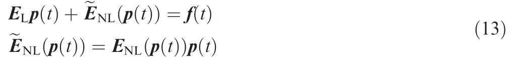
We introduce the vector form of nonlinear stiffness coeff icient into the structure equation as Eq.(13):
An ordinary polynomial method can be performed to curve fit the speci fic force and the corresponding displacement relationship.The polynomial expression of the nonlinear restoring forces,the same as nonlinear stiffness terms,can be expressed as the following form which is up to third order:
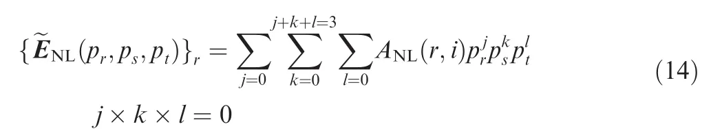
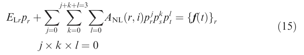
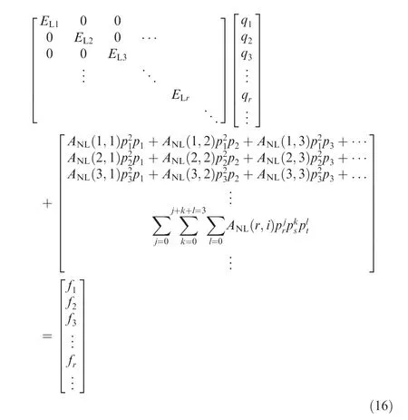
Nonlinear stiffness coefficient matric ANLis what we want to obtain by regression analysis.
Consider that there are NT sets of static test load cases we can get NT sets of the corresponding displacement after completing static FEM analysis of NT sets of test loads on the model in commercial finite element software.Translate the loads and deformation to modal space.For the sake of finding the unknown nonlinear modal stiffness terms,the restoring force in each of the test cases can be curve fitted in a least squares sense.The restoring forces corresponding tormode can be presented as
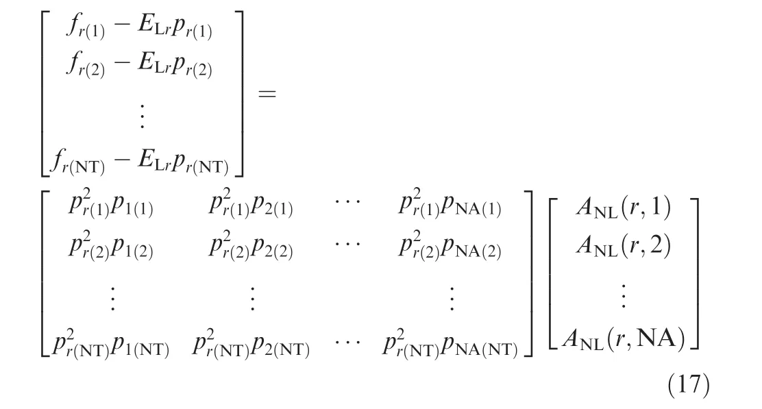
Problem has been translated to standard least square problem,after completing regression analysis to each order of modes we can get all of the nonlinear stiffness coefficients.Simplify Eq.(17)and regression problem can be presented in matrix short notation as

2.2.3.Strategy for generating test load cases
Through the above-presented analysis,the regression analysis is provided by the actual deformation and load testing after FEM analysis by commercial software package,so the accuracy of nonlinear stiffness coefficient directly depends on the rationality of selection of the test load case,which is related to the success of recovery of nonlinear structural equation.Selections of test load cases need to meet the following conditions:
(1)The selected cases must be able to reflect the linear and nonlinear factors of the structure.
(2)The selected cases must meet the characteristics of aerodynamics in aeroelastic analysis.
(3)The selected cases must be reasonable and interested in our research.
(4)The selected cases must meet the requirements of nonlinear FEM calculation cost and complexity,and the account of cases should be as fewer as possible.
It needs to emphasize that in condition(2),aerodynamic force on the wing should be follower force,which is more fit the actual characteristic of aerodynamic force.That is to say,taking oriented load as the load test cases cannot meet the requirement.In this paper,aerodynamic force under the wing’s deformation combining bending modes and torsion modes is chosen as test load case;meanwhile it holds that bending modes and torsion modes are regarded as normal modes to realize approximate analysis of follower force load.The formulation of wing’s deformation which causes aerodynamics forces should be

2.3.Non-planar aerodynamics method
The non-planar VLM is very useful in computing the aerodynamics of the aircraft with a deformed configuration considering non-planar effect.Ignoring the thickness of the wing,we can divide the middle camber surface of the wing platform into panels including vortex ring singularities,which is shown in Fig.1.Four segments of vortex line compose a vortex ring,while the main part is located at the quarter chord line of the panel.The midpoints of the segments are treated as the point of aerodynamics load action of the panel.The actual boundary condition is performed at the midpoint of the three quarters chord line,as the collocation point.We can obtain the velocity induced by the typical vortex ring at optional position by Biot-Savart law.In particular,the rings placed at the trailing edge require special disposition.
The wake shedding into the flow field is at each trailing edge along thexaxis,which is modeled by two semi-span training vortex lines(Fig.1(b)).We consider the influence of these two semi-infinite trailing vortex lines when computing the velocity by a trailing edge vortex ring element instead of the rear segment of the vortex ring.Then,the aerodynamics forces can be represented in a special formulation.24–26
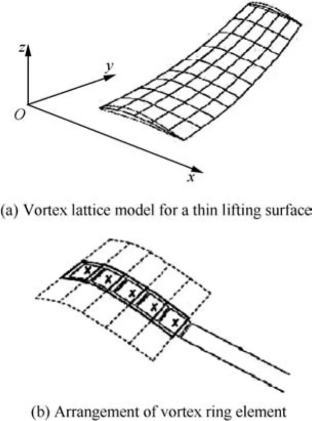
Fig.1 Non-planar vortex lattice model.
2.4.Surface spline interpolation
To couple aerodynamics and structure,the surface spline interpolation is applied.In most situations,the configuration of structure isembedded into a three-dimensionalspace.Deformed configuration is three-dimensional in usual,while the un-deformed configuration might be one-dimensional,two-dimensional or three-dimensional.
Whenngiven structural grids and the corresponding deformation vector USare confirmed,we can obtain the deformation vector UAofmaerodynamic grids by displacement interpolation.23

Here G is the spline matrix.Structure equivalence of the structure force system and aerodynamics force system is satisfied when the virtual work corresponding to virtual deflections by the aerodynamics loads FAand their equivalent structure forces FSare equal in force interpolation:


2.5.Static aeroelastic analysis method
Static aeroelasticity is the study that covers the interaction of aerodynamic and structural forces on a flexible structure with the whole geometric properties and the forces are being time invariant.This interaction results in elastic deformations of the lifting surface of the structures,hence the bending and the twist of the wing can be determined with respect to the flight condition of interest.The general form of aeroelastic static equation of motion can be represented as

HerefStructureis the structure deformation operator,frg the convergence deformation of wing,fAirthe aerodynamics operator,and fFgg a vector of applied loads(e.g.gravity).Note that the rigid body motions are not included in the system of equation as for all the cases considered in this part,the wing structure is usually clamped on the root.
The static aeroelastic analysis is based on nonlinear structure ROM and steady VLM,combining with surface spline interpolation to transfer information of force and displacement between structure and aerodynamic models.In this paper,we calculate the static aeroelastic stable deformation under the given airflow velocity.Fig.2 presents the iterative process.
2.6.Static aeroelastic trim analysis
There are two coupling modules in iterative calculation applied to the static aeroelastic trim analysis including geometric nonlinearity.One module is to compute aerodynamic forces and complete rigid trim analysis and the other module is to compute large deflection of structure.
Iterative process of static aeroelastic trim analysis including geometric nonlinearity starts with the input of structure/aerodynamics model in specified flight status as analysis flow chart presented in Fig.3.We can start iterative solution after we establish and initialize the aerodynamic and structural models.In each iterative calculation,we regenerate the aerodynamic grids according to the structure deformation which can be obtained in the previous cycle.

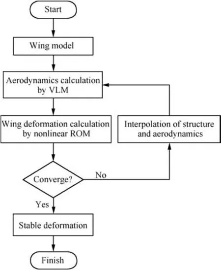
Fig.2 Iterative process of static aeroelastic analysis.
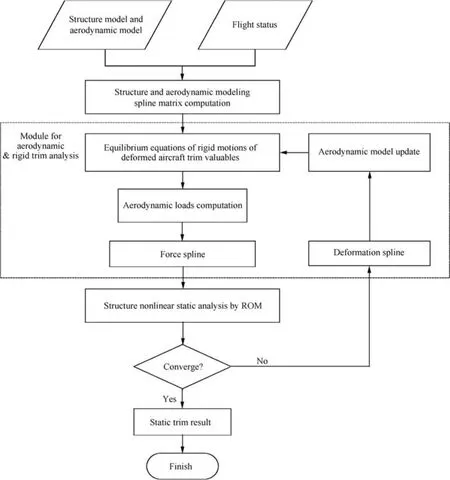
Fig.3 Iterative process of static aeroelastic trim analysis.
The equations of motion are shown as
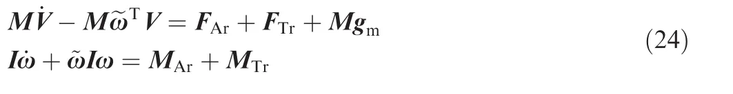
Here M and I are matrices of mass and inertia,V and x vector of velocity and angular velocity,F and M the vector of resultant force and moment.Subscript Ar represents that the physical quantity belongs to aerodynamic loads and subscript Tr represents that the physical quantity belongs to thrust and other external forces,and gmis the gravity vector.The aircraft motion equations have been performed in the body reference coordinate system for which the mean axes systemOxyzhas been selected.
3.Numerical example
3.1.Model
3.1.1.Wing model
To validate the accuracy of ROM and complete static aeroelastic analysis including geometric nonlinearity,a wing model is conducted.The wing model with large-aspect-ratio has large flexibility and parameters have been shown in Table 1.
As Fig.4 shows,the shape of the wing is constructed by twelve wing segments consisting of cotton paper and balsa wood.The wingtip store has a weight of 31.5 g and a length of 150 mm.Beam elements and lumped mass elements are used to simulate the stiffness and mass in structure FEM model as shown in Fig.5.
As there will exist lateral deformation of the model in geometric nonlinear analysis,two lateral modes have been taken into the establishment of ROM to evaluate the accuracy.Seven modes are used in the establishment of ROM in Table 2.Telescopic modes are solved by analytical method to recover lateral displacement in nonlinear analysis.
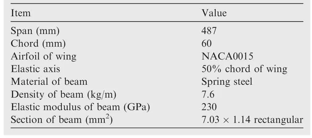
Table 1 Design parameters of wing model.
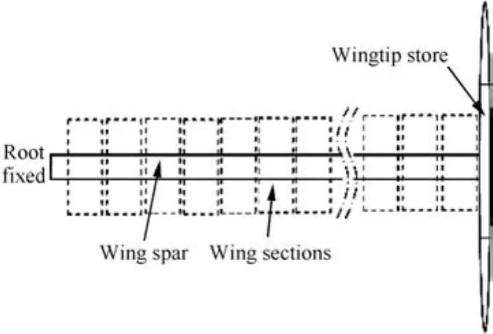
Fig.4 Layout of flexible wing.
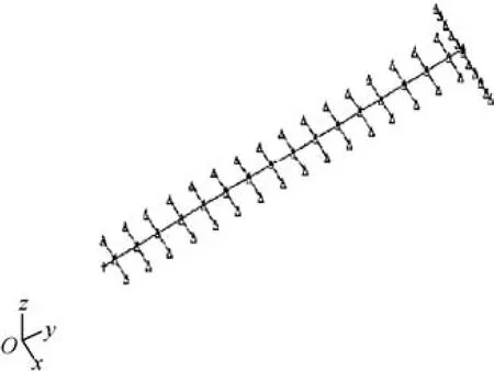
Fig.5 Structure finite element model of wing.
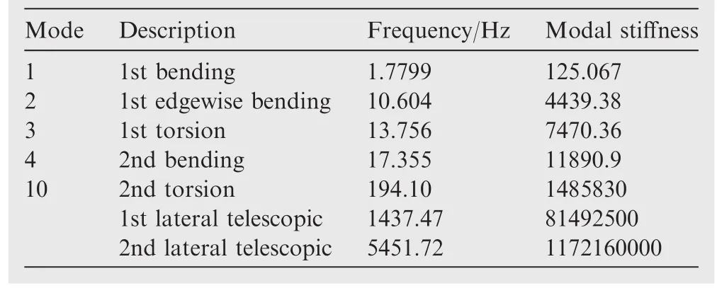
Table 2 Modes participated in establishment of ROM.
3.1.2.Aircraft model
A semi-span model of flexible aircraft is established for static aeroelastic trim analysis.Parameters of aircraft model are shown in Table 3,the aircraft model in Fig.6 and FEM model in Fig.7.The wing of aircraft is the same as wing model described before.Wingtip store has also been set in order to regulate the flutter characteristics.The wingtip store has a weight of 31.5 g and a length of 150 mm.In contrast to the flexible wing,the horizontal tail and fuselage have more large stiffness which could be regarded as rigid bodies.
3.2.Verification of nonlinear ROM
The accuracy of the estimated nonlinear ROM can be validated by comparing the calculation results of ROM and nonlinear FEM after applying the validating load on the wing model.
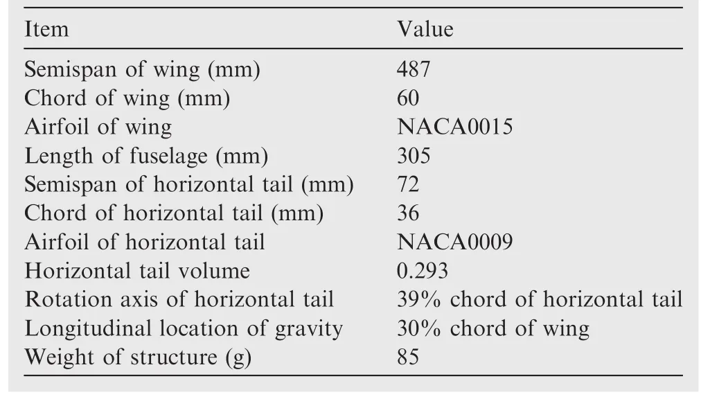
Table 3 Design parameters of aircraft model.
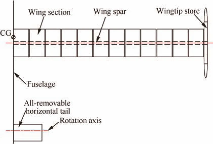
Fig.6 Layout of flexible aircraft.
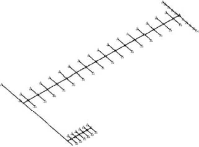
Fig.7 Structure finite element model of aircraft.
Nonlinear ROM is obtained by regression analysis from test load cases and the corresponding deformations,so the nonlinear structural equation must fit the result of all sets of test load cases and the corresponding deformation.More importantly,nonlinear structure equation should fit kinds of load in different forms and their deformation,having good adaptability in calculation to different forms of loads,then the ROM can be applied to structural and aeroelastic analysis reasonably.
Take four sets of validation load as examples and distribution of force on the wing model of those examples is shown in Fig.8.Load of case A is a distribution of actual aerodynamics force.Load of case B is a distribution of constant force.Load of case C is a distribution of linear increase force along the wing span.Load of case D is a distribution of force with two order functions.Calculation results of those cases are shown in Fig.9 with ROM solutions and FEM solutions being compared.Here black line with circle represents flapwise deformation of beam in ROM solutions and black line with cross represents flapwise deformation of beam in FEM solutions.Red line with circle represents edgewise deformation of beam in ROM solutions,and red line with cross represents edgewise deformation of beam in FEM solutions.ROM solutions can have a great agreement with nonlinear FEM solutions.The structure ROM established is reliable.
3.3.Static aeroelastic analysis of wing model
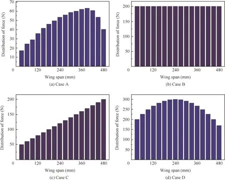
Fig.8 Distribution of force(validating load)on wing model.
In this paper,we calculate the static aeroelastic stable deformation at the given airflow velocity.Taking airflow velocity 33 m/s and angle of attack 0.0097 rad/0.556?as example,Fig.10 shows distribution of lift,drag and cross force on the wing after deformation is stable when calculation iterative progress of static aeroelastic analysis is converged.
It can be seen that the end of wing is significantly affected by downwash airflow and air force nearly has an ellipse distribution.Due to the clamping of wing root and freedom of wing tip,torsion of wing tip is large.Lift,drag and cross force are asymmetric at wing tip and wing root.The velocity 33 m/s in the above example is large,and thus the asymmetric is more significant.Air force has component of cross force,due to consideration of surface influence of wing’s large deformation,which is different from linear aerodynamics calculation.
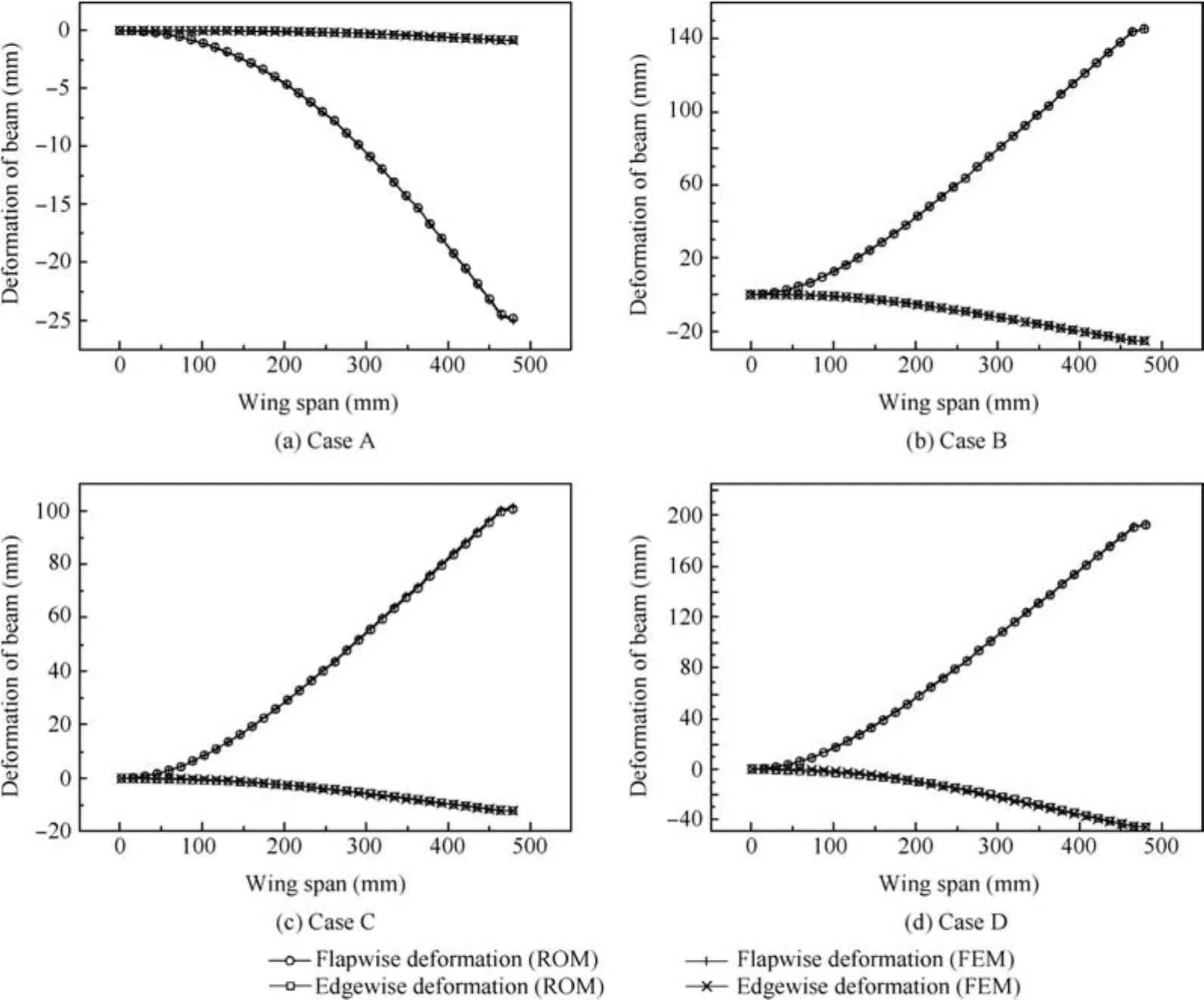
Fig.9 Calculation results of validating load.
Fig.11 shows the displacement of the wing along the three axis directions(Tx,Ty,Tz)which are computed by linear method and nonlinear ROM when iterative progress is converged.The results indicate that the displacement of the wing spar along thexaxis andyaxis calculated by the linear method equals zero.In contrast,the vertical displacement calculated by the linear method is much greater than the nonlinear results.In nonlinear analysis,the aerodynamics of the wing has follower force effect.The wing is bent and rotates with the effect of aerodynamics which has a significant influence on the distribution of aerodynamics.It cannot be considered in linear analysis.
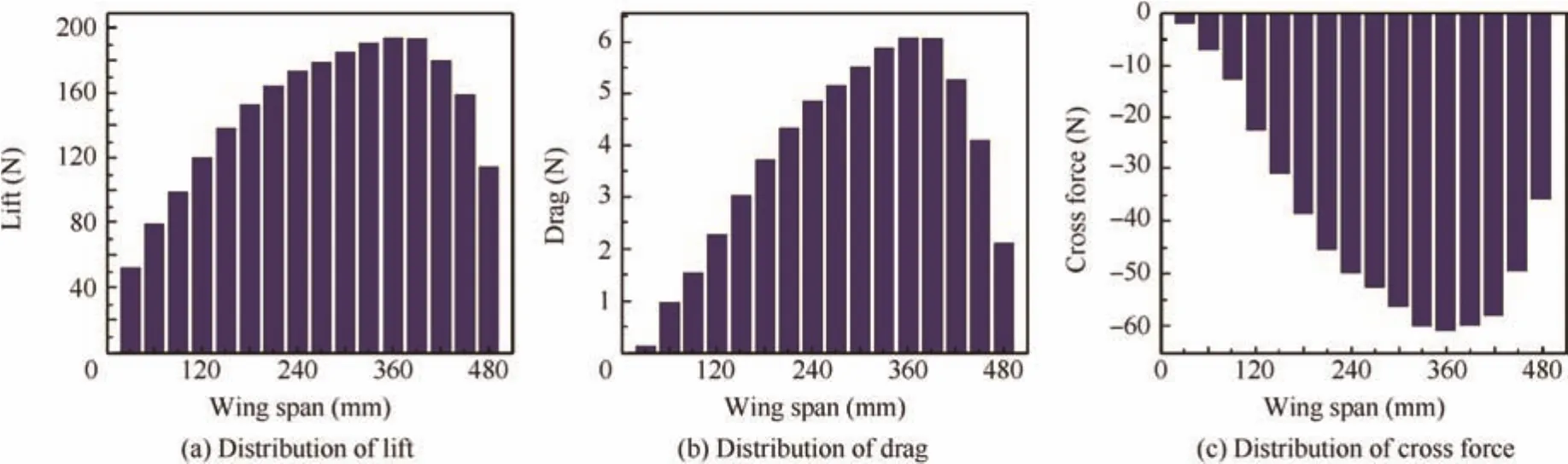
Fig.10 Distribution of aerodynamic force after calculation is converged.
Calculate the static aeroelastic stable deformation of wing in a certain range of airflow velocity.Table 4 presents a com-parison of vertical displacement of wing tip between nonlinear ROM solutions and FEM solutions in a range of velocity from 20 m/s to 34 m/s at angle of attack of 0.0097 rad/0.556?.
Fig.12 presents a comparison of vertical displacement of wing tip between nonlinear ROM solutions,nonlinear FEM solution,experimental results and linear solutions in a range of flight status set up before.
It can be seen that tip displacement of wing is close to zero when air speedVis close to 28 m/s when aerodynamic force equals gravity approximately.The tip displacement of wing changes into nonlinear growth with the increase of air speed.The static aeroelastic analysis solutions based on nonlinear ROM have a good agreement with the static aeroelastic analysis solutions based on nonlinear FEM,which prove the process established is accuracy and reasonable.There are some errors between experimental results and calculation results in medium speed condition,and the preliminary judgment of that is there are random disturbance errors in experiment with the corresponding conditions,and the model has some unknown factors that cannot be accurately modeled.These factors bring errors for calculation and experiment.It should be noted that tip displacement of wing in linear solution is 456.9 mm when air speed is 34 m/s,close to semi-span of the wing,which is apparently wrong.11In contrast,tip displacement in nonlinear ROM solution is 243.9 mm,nearly half of linear solution.There is a huge difference between the linear and nonlinear solutions in large deformation state.Actual wing model in wind tunnel test has been shown in Fig.13.
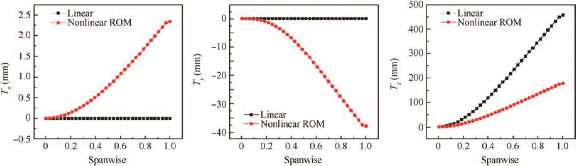
Fig.11 Displacement of wing spar along spanwise.
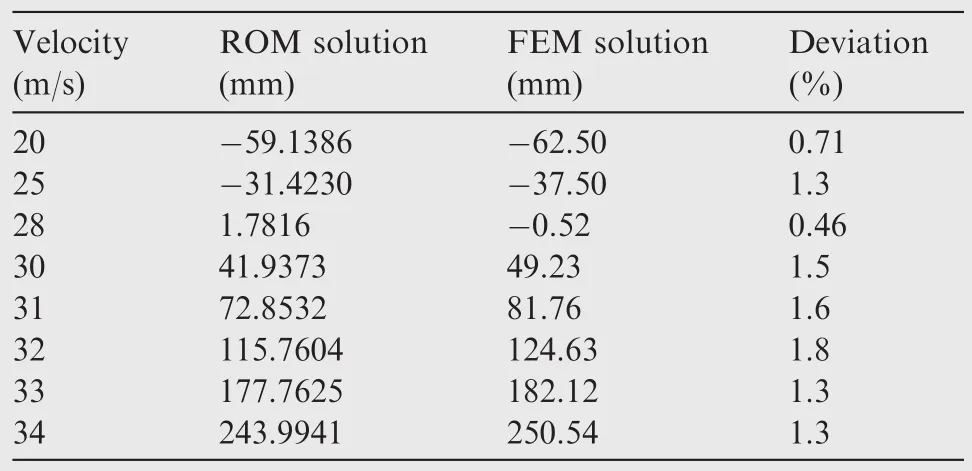
Table 4 Comparison of ROM and FEM solutions of stable static aeroelastic deformation.
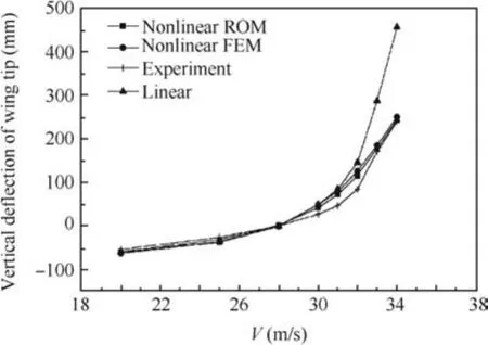
Fig.12 Comparison of ROM,FEM solutions and experimental results of stable static aeroelastic deformation.
3.4.Static aeroelastic trim analysis of aircraft model
3.4.1.Longitudinal trim analysis with different weights

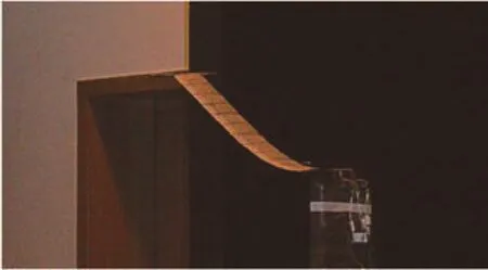
Fig.13 Actual wing model in wind tunnel.

3.4.2.Longitudinal trim analysis of flexible aircraft with different flight speeds
In another aspect of static aeroelastic longitudinal trim analysis,flight status of invariant weight 400 g and different flight speeds have also been analyzed.Same as analysis with different weights,the trim variables are the angle of attack a and elevator deflection de.Fig.16 shows the change of the trim variable with the flight speed increasing and Fig.17,the calculation result of vertical deformation of the wing.Nonlinear reduced order models method solutions,nonlinear FEM solutions and linear solutions have been compared in those figures.15
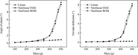
Fig.14 Variation of trim variable with different weights.
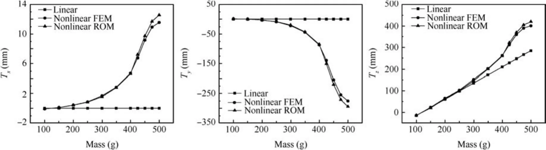
Fig.15 Vertical displacement variation of wing tip with different weights.
The result reveals that the trim variables of the aircraft decrease as the flight speed increases,and the trend is similar to the result obtained by the linear method.However,the structural lateral deformation and follower force effect of aerodynamics are considered in the nonlinear method,therefore,the result obtained by the nonlinear method is greater than the linear ones.It should be noted that with the flight speed getting larger(V>32 m/s),angle of attack and elevator deflection turn to increase.This change is caused by two different reasons.One reason is that the aerodynamics produces a positive torsional deformation on the wing,which increases the effective angle of attack of the wing profile.Therefore,the angle of attack for longitudinal trim is decreased.The other reason is that the lateral deformation of the wing becomes much more evident as the structural deformation keeps increasing with the speed,and that leads to a decrease of lift generating efficiency and an increase of angle of attack.
When flight speed is low,the lateral deformation of the wing is not obvious,and the first reason is the leading role,therefore the angle of attack decreases when the flight speed increases.As the flight speed keeps increasing,the lateral deformation of the wing becomes much more significant;the second reason also becomes more important than the first one.Therefore,the angle of attack turns to increase with the flight speed.15Lateral displacement equals zero all the time in linear analysis.
Most importantly,the solutions based on ROM method can reach a good agreement with nonlinear FEM method with small deviation.The structure analysis method of ROM can be applied to static aeroelastic trim analysis well.
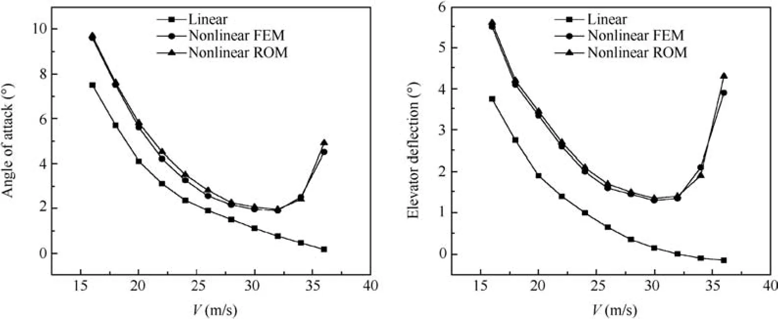
Fig.16 Variation of trim variable with different flight speeds.
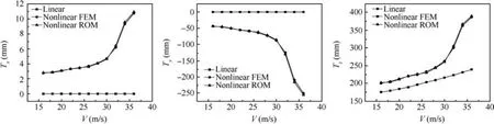
Fig.17 Vertical displacement variation of tip of wing with different flight speed.
4.Conclusions
In this paper,an effective method for the static aeroelastic analysis of flexible wing and the static aeroelastic trim analysis of flexible aircraft with large deformation has been performed.Main work represented is to improve the application of combined MFE method as structure ROM in aeroelastic analysis.Once the structure ROM is defined,non-planar effect of aerodynamics under the large deflection is in consideration which is computed by the non-planar VLM.Meanwhile,structure/aerodynamics coupling is completed by the surface spline method.Finally we can solve flexible wing/aircraft static aeroelastic problem by iterative solution method.
(1)The work presented here innovatively uses more highorder modes to recover the large deflection of wing to reflect the characteristic of geometric nonlinearities,that is in order to identify the nonlinear stiffness coefficients more exactly also.Meanwhile,the method sets the aerodynamic follower forces under certain deformation as test load cases in ROM which makes analysis closer to real flight condition and makes result more reasonable.Finally,aerodynamic influence coefficient matrix is changing considering the variation of wing’s deformation instead of a constant value based on the initial deformation.The nature of aerodynamics under the large deformation has been more considered.The method is computationally inexpensive compared to traditional nonlinear FEM.
(2)Whether it is in the static aeroelastic analysis of wing,or the static trim aeroelastic analysis of aircraft,large differences are observed between the linear and nonlinear solutions when the wing of aircraft has large deformation.Geometric nonlinearities cannot be ignored in aeroelastic analysis of very flexible aircraft.
(3)It can be seen from the calculated result that the aeroelastic analysis of wing based on ROM can achieve a good agreement with the analysis based on nonlinear FEM and deformation results in experiment.Nonlinear characteristics of flexible wing/aircraft can be figured out clearly.The structure analysis method of ROM can be applied to static aeroelastic analysis well.
(4)We introduce the MFE method into the static trim aeroelastic analysis innovatively.It can be seen from the calculated result that both the static aeroelastic longitudinal trim analysis of different velocities and weight of flexible aircraft based on ROM can achieve a good agreement with the analysis based on nonlinear FEM.Nonlinear characteristics of flexible wing/aircraft can be figured out clearly.It is valuable to theoretical analysis and engineering application in aeroelastic with geometric nonlinearities.
1.Patil MJ,Hodges DH.On the importance of aerodynamics and structural geometrical nonlinearities in aeroelastic behavior of high-aspect-ratio wings.41st AIAA/ASME/ASCE/AHS/ASC structures,structuraldynamics,andmaterialconferenceand exhibit.Reston:AIAA;2000.
2.Patil MJ.Nonlinear aeroelastic analysis,flight dynamics,and control of a complete aircraft[dissertation].Atlanta (GA):Georgia Institute of Technology;1999.
3.Darecki M.Flightpath 2050:Europe’s vision for aviation maintaining global leadership&serving society’s needs.Luxembourg,Belgium:Publications Office of the European Union;2011.
4.Cesnik CES,Hodges DH,Patil MJ.Aeroelastic analysis of composite wings.37th structures,structural dynamics and materials conference;1996.
5.Patil MJ,Hodges DH,Cesnik CES.Limit cycle oscillations in high-aspect-ratio wings.J Fluids Struct2001;15(1):107–32.
6.Patil MJ,Hodges DH,Cesnik CES.Characterizing the effects of geometrical nonlinearities on aeroelastic behavior of high-aspectratio wings.Int forum aeroelasticity struct dynamics1999.
7.Tang DM,Dowell EH.Effects of geometric structural nonlinearity on flutter and limit cycle oscillations of high-aspect-ratio wings.J Fluids Struct2004;19(3):291–306.
8.Xiang JW,Yan YJ,Li DC.Recent advance in nonlinear aeroelastic analysis and control of the aircraft.Chin J Aeronaut2014;27(1):12–22.
9.Tang D,Dowell EH.Experimental and theoretical study on aeroelastic response of high-aspect-ratio wings.AIAA J2001;39(8):1430–41.
10.Palacios R,Cesnik CES.Static nonlinear aeroelasticity of flexible slender wings in compressible flow.46th AIAA/ASME/ASCE/AHS/ASC structures,structural dynamics,and materials conference.Reston:AIAA;2005.
11.Xie CC.Static/dynamics coupling theory and test study of aircraft aeroelastic stability[dissertation].Beijing:Beihang University;2009[Chinese].
12.Xie CC,Leng JZ,Yang C.Geometrical nonlinear aeroelastic stability analysis of a composite high-aspect-ratio wing.Shock Vib2008;15(3–4):325–33.
13.Howcroft C,Cook R,Calderon D,Lambert L,Castellani M,Cooper JE,et al.Aeroelastic modeling of highly flexible wings.15th dynamics specialists conference.Reston:AIAA;2016.
14.Zhang J.Modeling and simulation of coupled nonlinear aeroelasticity and flight dynamics for flexible aircraft[dissertation].Beijing:Beihang University;2010[Chinese].
15.Yang C,Wang LB,Xie CC,Liu Y.Aeroelastic trim and flight loads analysis of flexible aircraft with large deformations.Sci China2012;55(10):2700–11.
16.Wang LB,Xie CC,Yang C.Static aeroealstic analysis of flexible aircraft with large deformations.54st AIAA/ASME/ASCE/AHS/ASCstructures,structuraldynamics,andmaterialconference.Reston:AIAA;2013.
17.Demasi L,Palacios A.A reduced order nonlinear aeroelastic analysis of joined wings based on the proper orthogonal decomposition.51st AIAA/ASME/ASCE/AHS/ASC structures,structural dynamics,and material conference.Reston:AIAA;2010.
18.Hodges DH.Geometrically exact,intrinsic theory for dynamics of curved and twisted anisotropic beams.AIAA J2003;41(6):1131–7.
19.Wang YN,Wynn A,Palacios R.Robust aeroelastic control of very flexible wings using intrinsic models.54st AIAA/ASME/ASCE/AHS/ASC structures,structural dynamics,and material conference.Reston:AIAA;2013.
20.Wang YN,Wynn A,Palacios R.Nonlinear model reduction for aeroelastic control of flexible aircraft described by large finite element models.55st AIAA/ASME/ASCE/AHS/ASC structures,structural dynamics,and material conference.Reston:AIAA;2014.
21.McEwan MI,Wright JR,Cooper JE,Leung AYT.A combined modal/finite element analysis technique for the dynamic response of a nonlinear beam to harmonic excitation.J Sound Vibr2001;243(4):601–24.
22.Harmin MY,Cooper JE.Aeroelastic behavior of a wing including geometric nonlinearities.Aeronautical J2011;115(1174):767–77.
23.Xie CC,Yang C.Surface splines generalization and large deflection interpolation.J Aircraft2007;44(3):1024–6.
24.Xie CC,Wang LB,Yang C,Liu Y.Static aeroelastic analysis of very flexible wings based on non-planar vortex lattice method.Chin J Aeronaut2013;26(3):514–21.
25.Liu Y,Xie CC,Yang C,Cheng J.Gust response analysis and wind tunnel test for a high-aspect ratio wing.Chin J Aeronaut2016;29(1):91–103.
26.Gabor OS,Koreanschi A,Botez RM.A new non-linear vortex lattice method:applications to wing aerodynamic optimizations.Chin J Aeronaut2016;29(5):1178–95.
18 March 2016;revised 18 July 2016;accepted 15 August 2016
Available online 16 February 2017
*Corresponding author.
E-mail address:xiechangc@163.com(C.Xie).
Peer review under responsibility of Editorial Committee of CJA.
杂志排行

CHINESE JOURNAL OF AERONAUTICS的其它文章
- Dynamics of air transport networks:A review from a complex systems perspective
- ATM performance measurement in Europe,the US and China
- Network analysis of Chinese air transport delay propagation
- Robustness analysis metrics for worldwide airport network:A comprehensive study
- Evolution of airports from a network perspective–An analytical concept
- Methods for determining unimpeded aircraft taxiing time and evaluating airport taxiing performance