Dynamic response analysis under atmospheric disturbances for helicopters based on elastic blades
2017-11-20TongLiuYutingDaiGuanxinHongLinpengWang
Tong Liu,Yuting Dai,Guanxin Hong,Linpeng Wang
School of Aeronautic Science and Engineering,Beihang University,Beijing 100083,China
Dynamic response analysis under atmospheric disturbances for helicopters based on elastic blades
Tong Liu,Yuting Dai*,Guanxin Hong,Linpeng Wang
School of Aeronautic Science and Engineering,Beihang University,Beijing 100083,China
Dynamic model;Elastic;Helicopter;Time domain analysis;Trimming;Wind shear
A flight dynamics model based on elastic blades for helicopters is developed.Modal shape analysis is used to describe the rotating elastic blades for the purpose of reducing the elastic degrees of freedom for blades.The analytical result is employed to predict the rotor forces and moments.The equilibrium equation of the flight dynamics model is then constructed for the elastic motion for blades and the rigid motion for other parts.The nonlinear equation is further simplified,and the gradient descent algorithm is adopted to implement the trim simulation.The trim analysis shows that the effect of blade elasticity on the accuracy of rotor forces and moments is apparent at high speed,and the proposed method presents good accuracy for trim performance.The timedomain response is realized by a combination of the Newmark method and the adaptive Runge-Kutta method.The helicopter control responses of collective pitch show that the response accuracy of the model at a yaw-and-pitch attitude is improved.Finally,the influence of blade elasticity on the helicopter dynamic response in low-altitude wind shear is investigated.An increase in blade elasticity reduces the oscillation amplitude of the yaw angle and the vertical speed by more than 70%.Compared with a rigid blade,an elastic blade reduces the vibration frequency of the angular velocity and results in a fast return of the helicopter to its stable flight.
1.Introduction
When a helicopter encounters atmospheric disturbances,the flapping motion of the rotor blade causes a hysteresis effect on the response of the aircraft fuselage.1This phenomenon affects the judgment of the pilot on the helicopter’s flight attitude and endangers the helicopter’s flight safety seriously.Helicopter movement exhibits obvious nonlinear features because of the coupling characteristics among the helicopter rotor,fuselage,lifting surface,and other components,such as inertia coupling,structure coupling,motion coupling,and aerodynamic coupling.2In fact,the helicopter rotor blade rotates at high speed with high-order nonlinear flapping motion and elastic deformation.Therefore,a helicopter nonlinear dynamics model that considers blade elasticity and exhibits a high level of simulation fidelity can precisely estimate the characteristics of blade flapping.This model is meaningful for research on helicopters under atmospheric disturbances,especially in assessment of flying quality,design of control systems,and analysis of stability and maneuverability.
Crocco3and Hohenemser4used an initial dynamics model of helicopters for the analysis of trim and stability.This model considers six degrees of freedom of a rigid body motion fuselage only.With the development of high-speed helicopters,the need for a reliable design of flight control systems has prompted interest in improving the accuracy of a flight dynamics model coupled with a sophisticated rotor model.The typical models are the ARMCOP general mathematical model proposed by the AMES Research Center,5,6the GENHEL model designed by Sikorsky Aircraft Corporation,7the affine nonlinear model established by Yang,8and the helicopter nonlinear dynamics model established by Chen9for the study of maneuver flight.However,all these models ignore the effect of elastic deformation of blades to reduce the coupling between helicopter components and simplify the dynamics models.Therefore,reflectingthecharacteristicsofbladeflappingmotion is difficult;this difficulty can affect the prediction of rotor aerodynamic loads and reduce the level of simulation fidelity.
Dynamics models considering the effect of blade elasticity are constantly developed.Theodore and Celi10described a flight dynamics simulation model,which includes the effects of blade flexibility with coupled flap-lag-torsion degrees of freedom and a free-wake inflow formulation.Kim11proposed a calculation model for the aerodynamic loads of the main helicopter elastic blade propeller in hover and forward flights.Li and Chen12established a nonlinear flight dynamics model considering the flap-lag-torsion coupling of the elastic blade.These methods have improved the accuracy of model calculations,which apply finite element analysis to an elastic blade model.However,the obtained large computational overhead prohibits the deployment of such methods in real-time flight dynamics applications,such as flight simulation under atmospheric disturbances.
Considering the abovementioned studies,this work aims to develop a helicopter dynamics model based on an elastic blade thatcanbeusedinreal-timeflightsimulationunderatmospheric disturbances.The specific objectives of the study are as follows:
(1)To describe a real-time flight dynamics simulation model that includes the flapping dynamics equation of the elastic blade and the formulation of rotor forces and moments exerted on the aircraft fuselage.
(2)To identify the capability of the model to obtain accurate estimates of trim performance by comparisons with flight test data.
(3)To assess the effects of rotor blade elasticity on the accuracy of rotor forces and moments.
(4)To realize time-domain response simulation of the helicopter with the dynamics model based on the elastic blade.
(5)Tousetheestablished modelin investigating the dynamic response of the helicopter in low-altitude wind shear.
2.Mathematical model
2.1.Flapping dynamic equation of an elastic blade
Yang8described a mathematical model of an affine nonlinear flight dynamic system for a single rotor.The rotor blade is assumed to be rigid with a blade hinge offset from the center of rotation and a spring about the flap hinge.The lag motion is ignored,and the value of the flapping angle b is supposed to be small.Linear coupling is considered between torsion and flapping.The flapping dynamic equation of the rigid blade in the model according to the equilibrium of bending moment can be expressed as

whereC1,C2,andC3are the coefficients of the flapping equation.Considering the deformation of the elastic blade,the flapping angle of the blade changes in the spanwise direction.In this study,the blade piecewise discrete method is adopted to indicate the flapping angle of the elastic blade.
With a large aspect ratio,the blade can be simplified as a cantilever beam;a two-node beam element is used to discretize the blade.The bending deformation of the elastic blade in a main rotor hub-rotation system(Sr)is shown graphically in Fig.1.
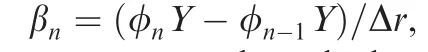
Without considering the root offset distancee,the hinge offset distancee0,handAfor coordinates,and the tip loss(1?B)R,the blade is divided intoNrsections equally.Notably,Bis the coefficient of the tip loss andRis the blade radius.xnandrnare the distance from thenth segment to the root and the hinge.FZ,nis the rotor thrust generated by thenth segment.The flapping deformation on every micro-segment is assumed to be negligible,and the first harmonic form of the flapping angle on thenth segment is defined as

The flapping mode degree of freedom is used to indicate the discrete flapping angle on each segment.The structural dynamic equation with the first-order modal shape under an aerodynamic load FZ(t)can be expressed as


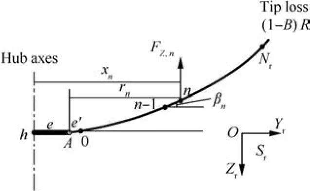
Fig.1 Bending deformation of elastic blade.
Similarly,the aerodynamic force at the hub direction can be written as the following first harmonic form:

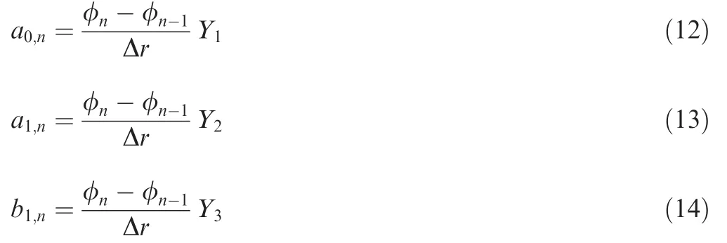
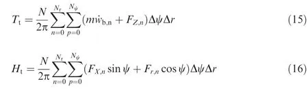
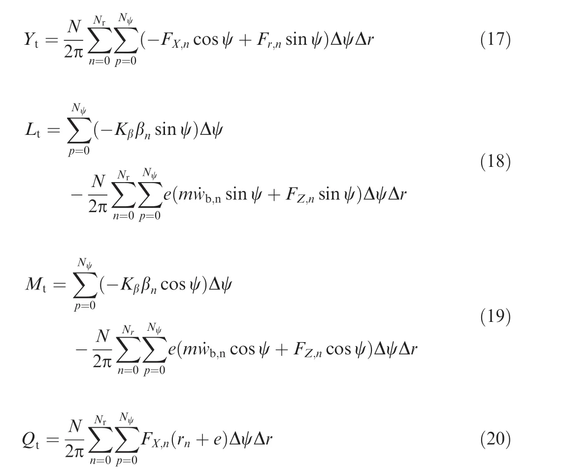
2.2.Formulation of rotor forces and moments with elastic blades
The rotor forces and moments acting on the rigid blade can be calculated by the integration method8or the computational fluid dynamics(CFD)method.13These methods are unsuitable for the elastic blade dynamics model whereas viable for the calculation of the elastic blade aerodynamic force integral through the piecewise summation method of the azimuth angle and the blade span finite element.Then,rotor forces and moments exerted on the aircraft fuselage,including the rotor thrustTt,horizontal forceHt,side forceYt,rolling momentLt,pitching momentMt,and torsional momentQtin the main rotor hub-airflow system,are mathematically expressed as
2.3.Dynamics model for a helicopter with elastic blades
The helicopter nonlinear dynamics model with elastic blades can be defined after building the flapping dynamics equation of the elastic blade and the algorithm of rotor forces and moments;the dynamics equation of the mass center translation,the dynamics equation of the mass center rotation,the geometrical relationship between the attitude angle and the angular velocity,the flapping dynamics equation of the tail rotor,and the dynamic inflow equation of the ANSM model are also obtained.8The model can be expressed by a firstorder differential equation as shown below,where the subscript ED represents the dynamics model that considers blade elastic deformation.

where XEDis the state vector,including the velocity,angular velocity,attitude angle,flapping coefficient,dynamic inflow coefficient,and other state parameters.U is the control vector,including the main rotor pitch h0M,tail rotor pitch h0T,lateral cyclic pitchA1C,and longitudinal cyclic pitchB1C.The state vector AEDand the control matrix BEDare the functions of the blade azimuth angle,helicopter component parameters,and state parameters.
3.Trim analysis
3.1.Method of trim analysis
During a steady flight of the helicopter,the derivatives to time of each state variable are all zero.The angular velocity and acceleration of the aircraft fuselage is also zero regardless of the sideslip flight of the helicopter.The dynamic equation can be simplified into an equilibrium equation as

The trim variable vector is written as
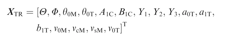
The gradient descent algorithm14is a mature and effective numerical analytical method.This algorithm is similar to the solution of a nonlinear algebraic equation for the extreme value problem of an objective function.The algorithm can be successfully used to solve nonlinear equation groups.To improve the efficiency and convergence of the trim algorithm,the equilibrium equation is further simplified.The trim variable is simplified as

The equilibrium equation only considers six equilibrium equations of the aircraft fuselage.Other trim variables are solved in each iteration through the flapping dynamics equation of the elastic blade,the flapping dynamics equation of the tail rotor,and the dynamic inflow equation.The objective function can be defined as
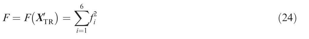
wherefiis the equilibrium equation of the helicopter.The trim simulation calculation of the helicopter is realized according to the iteration step of the gradient descent algorithm.15The process of trimming simulation is shown in Fig.2.

3.2.Model validation
To validate the precision of the helicopter nonlinear dynamics model with an elastic blade,the trim performance of a UH-60A helicopter under a steady level flight is calculated using the established model;the obtained results are then compared with the flight test data16and trim results of the dynamics model with a rigid blade.17The trim performance of UH-60A helicopters is selected because of the availability of a complete database system containing wind tunnel test data and flight test data of UH-60A helicopters for verifying most dynamics models.
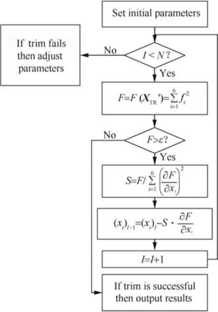
Fig.2 Process of trimming simulation.
According to the flight test conditions,the rotor speed is set as 26.83 rad/s,the tail rotor speed is set as 124.64 rad/s,the flight height is set as 1600.2 m,and the helicopter flight weight is set as 7257.9 kg.Moreover,Nr=10 andNw=20.The first flapping model frequency x=46.39 rad/s.The four positions of the joystick including collective pitch control,tail rotor control,lateral cyclic control,and longitudinal cyclic control under a steady forward flight speed ofV=0–70 m/s can be calculated using the trim simulation.Fig.3 presents the comparison of trim results.
The comparison of trim results shows a good correlation between the present approach and the flight test data.Compared with the trim results of the model with a rigid blade,the trim results of lateral cyclic control and longitudinal cyclic control are closer to the flight test data.Fig.3 also illustrates that the collective pitch control results agree well with the flight test data at medium-speed flights,but a discrepancy appears between the results at high-speed flights.The reason is attributed to the difference between the elastic blade model parameters and the actual parameters of a helicopter.Therefore,the influence of rotor blade elasticity on the trim performance at different flight speeds must be analyzed to further verify the accuracy of the model.
It should be noted that when the rotational speed of the rotor is constant,with a higher forward flight speed,the linear velocity of the blade tip increases.When the linear velocity of the blade tip approaches the speed of sound,the drag coeff icient will increase rapidly because of the compression of the air,leading to a significant drop of the aerodynamic performance of the rotor.Due to the fact that the proposed model fails to consider the compression effect,the model is only applicable for simulating analysis in a restricted forward flight speed,which ensures that the linear velocity of the blade tip is not up to the range of transonic speed.
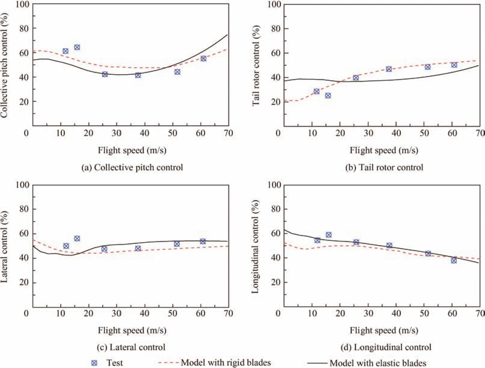
Fig.3 Comparison of trim results between simulation and flight test data.
3.3.Influence of rotor blade elasticity
To analyze the influence of rotor blade elasticity on the trim performance and rotor forces and moments,a type of helicopter model is used as an example in this article.The model presents a flying quality of 5250 kg,a rotor wing revolving speed of 31.85 rad/s,and a rotor wing radius of 6.75 m.
Notably,Nr=10 andNw=20,under a steady flight with a helicopter forward flight speed ofV=36,180,252 km/h;the first flapping model frequencies are 42.90,46.39,61.78,137.57,149.15,205.71 rad/s.The changes in the main rotor pitch,tail rotor pitch,lateral cyclic pitch,longitudinal cyclic pitch,pitch angle,and roll angle with blade elasticity at different speeds are calculated.The trim parameters are shown in Fig.4.It was replaced with the the first flapping model frequency,which can represent the blade elastic properties better.In this section,change trend of trim parameters under different speeds is the focus of attention.In order to show the effect of the rotor blade elasticities to the trim parmenters,the horizontal coordinate is represented by an equidistant form.
The calculation results show that blade elasticity slightly influences the trim performance at low and medium speeds,except the tail rotor pitch.However,each of the trim parameters changes significantly with an increase in blade elasticity when the helicopter flies at a high speed.The pitch angle of the helicopter,as an exception,is barely affected by the blade elasticity regardless of speed.Considering that the trim performance is mainly determined by the rotor aerodynamic loads,the influences of rotor blade elasticity to the main rotor aerodynamic loads are presented in Fig.5.In the figure,XMR,YMR,andZMRare the main rotor force components;LMR,MMR,andNMRare the rolling,pitching,and yawing moments,respectively.
The calculation results illustrate that the main rotor force is insignificantly influenced by blade elasticity at low and medium speeds.However,an increase in blade elasticity signif icantly affects the main rotor forces at high speed.ZMRpresents the largest influence among all components.This effect explains the significant influence of elastic modulus on the main rotor pitch at high speed only.The rolling moment of the helicopter is mainly attributed to the main rotor;hence,the effect of blade elasticity on the roll angle is consistent with that on the rolling moment of the main rotor.Moreover,given the influence of the horizontal tail,the pitch angle is barely affected by the pitching moment.
The rotor load increases with the flight speed,thereby resulting in serious blade deformation.The change in blade elasticity obviously affects the blade deformation,resulting in a certain effect on the trim performance at high speed.Therefore,the established helicopter dynamics model can reflect the actual characteristics of the main rotor and presents sufficient fidelity for simultaneous predictions of rotor forces and moments.
4.Response analysis
4.1.Algorithm of time-domain response
The discrete dynamic equation is used for the elastic blade.Thus,the equation can be performed through the Newmark method.18The time-domain response of flapping coefficients can be realized accordingly.Considering that the dynamics model can still be represented as a first-order ordinary differential equation,the rest of the parameters can still be calculated by the adaptive Runge-Kutta method.19The process of timedomain response simulation is shown in Fig.6.
Given that the two methods are adopted to achieve realtime integration,the time step must be cautiously selected for calculation.A small time step results in high accuracy for the adaptive Runge-Kutta method.However,the time step of the Newmark method is related to the load time process and the modal frequency of the system.Hence,the time step size must be selected according to the need of simulation.
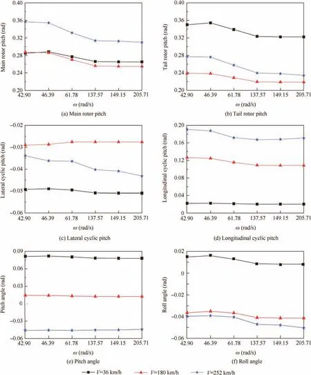
Fig.4 Trim results with different rotor blade elasticities in forward flight.
4.2.Helicopter control response of collective pitch
In analyzing the influence of the helicopter control response of collective pitch,the UH-60A helicopter is still used with a forward flight speed ofV=185 km/h.According to the flight condition of the flight-test,the collective pitch control input by the driver is 1.27 cm upward and the process of control is shown in Fig.7.
Fig.8 shows the comparison between the control response by the established model,the flight test data16,and the results of the dynamics model with rigid blades17.
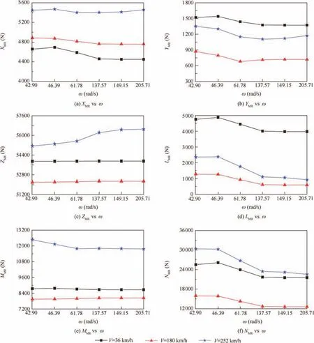
Fig.5 Comparison of the main rotor force components under different trim states.
When the helicopter is flying in a steady level flight mode,flight state parameters will remain stable,and respective responses between rigid and elastic blades are basically consistent with each other.After the helicopter experiences disturbances as a result of the collective pitch control input,the impact of blade elasticity on the helicopter performance will be significant.The results show that the control responses of the roll and yaw angles of the helicopter are close to the flight test results.However,some differences are observed in the pitch angle.The reason is that the pitching moment of the helicopter is mainly supplied by the horizontal stabilizer,and the improvement in the calculation accuracy of the main rotor cannot improve the control response accuracy of the pitch angle.On the contrary,compared with the model with rigid blades,the accuracy of the dynamic response analysis can be improved by considering blade elasticity.Thus,the model can be effectively applied to the analysis of the helicopter dynamic response under atmospheric disturbances.
5.Helicopter dynamic response under atmospheric disturbances
The first flapping mode represents the flapping elastic deformation in the established helicopter dynamics model.The model exhibits no additional degree of freedom in the state parameter vector of the helicopter model.The model can be applied in the real-time dynamic response simulation of helicopter flight under atmospheric disturbances.
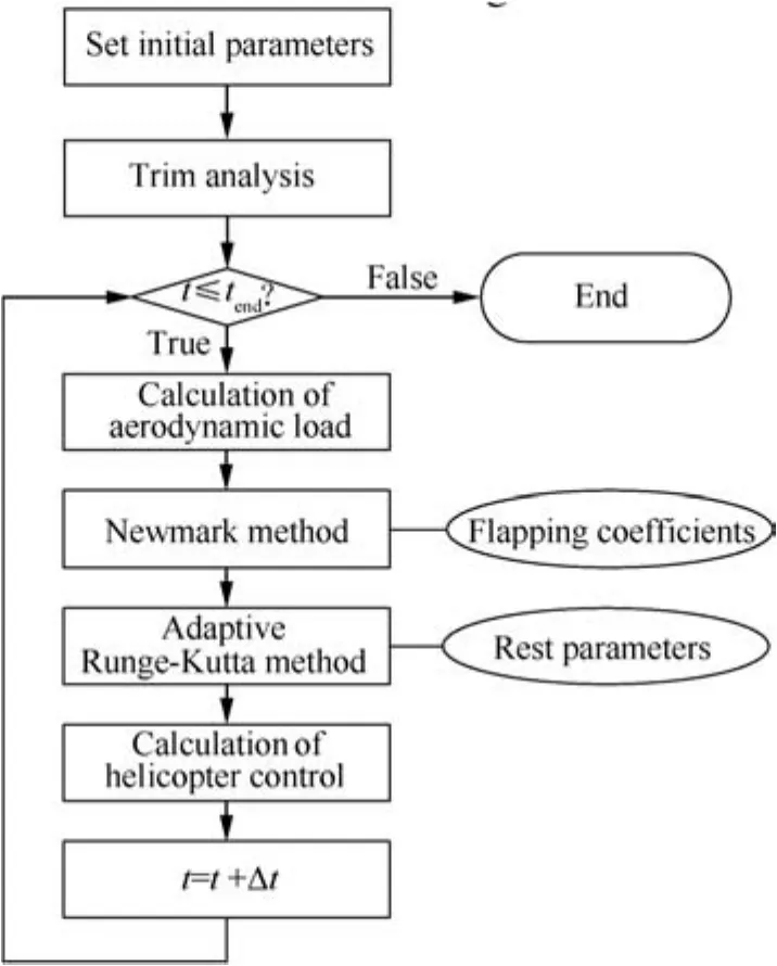
Fig.6 Process of time-domain response simulation.
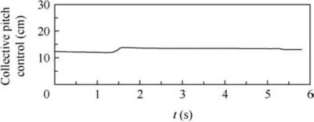
Fig.7 Process of collective pitch control input.
The low-altitude wind shear is an atmospheric disturbance phenomenon and is known as the ‘hidden killer” for aviation safety.20This parameter is used in analyzing the influence of blade elasticity on the helicopter dynamic response under atmospheric disturbances.The wind field model is defined as21

whereVais the low-altitude wind shear strength andh0is the ground roughness.Empirically,h0=0.046 m under the condition of vertical takeoff and landing,andh0=0.61 m in other flight altitudes.
The helicopter is assumed to fly forward at a speed of 252 km/h with a flight height of 600 m.The helicopter suffers from the low-altitude wind shear at 0.5 s from the incoming flow direction,which is set asVa=1 m/s andh0=0.61 m.Comparisons of the time-domain dynamic response of the state parameters are performed between model with elastic blades(x=46.39 rad/s)and rigid blades(x=149.15 rad/s).Fig.9 shows the results of simulation in terms of vertical speed,pitch angle,yaw angle,roll angle,pitching angular velocity,yaw angular velocity,and roll angular velocity.
The response results demonstrate that blade elasticity apparently affects the response process of simulation.Specif ically,the influence of blade elasticity on the yaw angle is most obvious among all parameters.Compared with the rigid blade,the elastic blade can significantly increase the vibration amplitude of the yaw angle to more than 70%.In addition,for the motion parameters of the helicopter,the influence of blade elasticity on the vibration amplitude of the vertical speed is higher than that on the angular velocity.With an increase in elasticity,the vibration amplitude of the vertical speed can be controlled.However,a serious vibration phenomenon occurs on the angular velocity.This phenomenon increases the time for the helicopter to return to a stable flight after entering the wind field.The vibration amplitude of the parameters can be reduced with an increase in blade elasticity.However,the vibration frequency can increase accordingly.
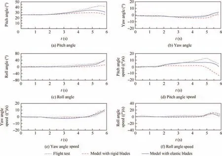
Fig.8 Comparison of control response of collective pitch between simulation and flight test data.
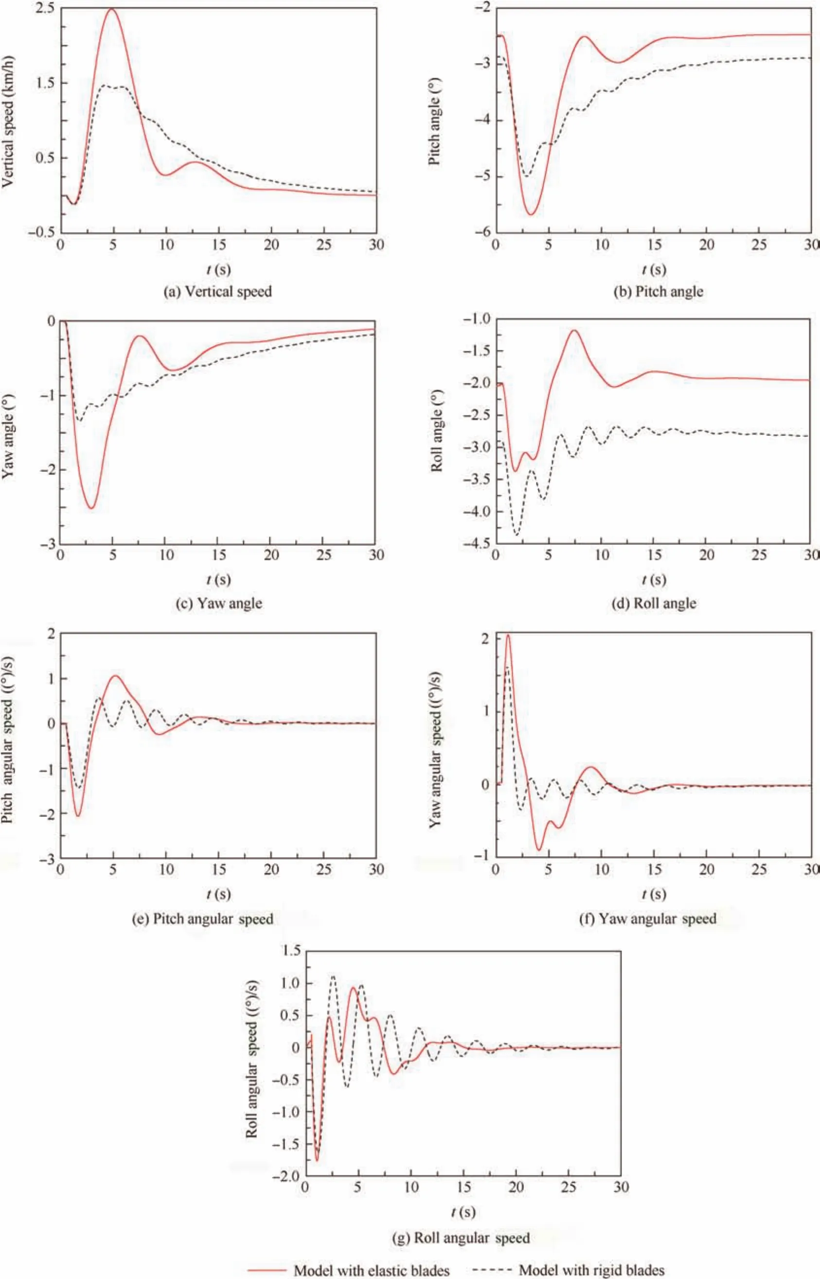
Fig.9 Dynamic response of helicopter in low-altitude wind shear.
With regard to helicopter design,an increase in the vibration amplitude can cause a certain influence on the structural safety.An increase in the vibration frequency can also affect the operating safety of the helicopter.Hence,the blade must be designed according to the functions,materials,controls,and other aspects of the helicopter.The safety performance of the helicopter design can be improved by establishing a balance between structural safety and operating safety.
6.Conclusions
A helicopter dynamics model with elastic blades is proposed for the simulation of the dynamic response of a helicopter under atmospheric disturbances.The proposed model presents sufficient fidelity for the prediction of trim performance and rotor aerodynamic loads particularly at high speed.The conclusions of this work can be summarized as follows:
(1)The developed helicopter dynamics model presents a high level of simulation fidelity without an addition of degrees of freedom.This model can be applied to studies on real-time and non-real-time numerical simulation of helicopters and other research on aerodynamic features.
(2)Blade elasticity significantly influences the estimation of the rotor forces and flight status at high speed.Therefore,the elastic deformation of the blade must be considered in the dynamics model of a helicopter.
(3)The established modelcan predictthe dynamic response of a helicopter in low-altitude wind shear.An increase in blade elasticity can improve the rotor aerodynamic loads and reduce the vibration amplitude of the helicopter flying parameters in a wind field but increase the vibration frequency.Consequently,the effects of blade elasticity on structural safety and operating safety must be considered comprehensively when designing helicopters.
Acknowledgements
This study was co-supported by the National Natural Science Foundation of China–China(No.11302011)and the Specialized Research Fund for the Doctoral Program of Higher Education–China(No.20131102120051).
1.Gao H.Research on helicopter flight characteristics in wind shear[dissertation].Nanjing:Nanjing University of Aeronautics and Astronautics;2009[Chinese].
2.Yang C,Song SF.The analysis about current situation and development of helicopter dynamics.J Beijing Univ Aeronaut Astronaut1995;21(2):46–52[Chinese].
3.Crocco GA.Inherent stability of helicopters.Washington D.C.:NASA;1923.Report No.:NACA-TM-234.
4.Hohenemser K.Dynamic stability of a helicopter with hinged rotor blades.Washington D.C.:NASA;1938.Report No.:NACA-TM-907.
5.Chen RTN.A simplified rotor system mathematical model for piloted flight dynamics simulation.Washington D.C.:NASA;1979 Report No.:NASA-TM-78575.
6.Chen RTN.Effects of primary rotor parameters on flapping dynamics.Washington D.C.:NASA;1980 Report No.:NASATP-1411.
7.Howlett JJ.UH-60A Black Hawk engineering simulation program:mathematical model.Washington D.C.:NASA;1981 Report No.:NASA-CR-166309.
8.Yang C.A mathematical model and validation of affine nonlinear system for helicopter flight dynamics[dissertation].Beijing:Beihang University;1995[Chinese].
9.Chen RL.A mathematical model of helicopter flight dynamics and investigation of maneuverability[dissertation].Nanjing:Nanjing University of Aeronautics and Astronautics;1998[Chinese].
10.Theodore C,Celi R.Helicopter flight dynamic simulation with refined aerodynamics and flexible blade modeling.J Aircraft2002;39(4):577–86.
11.Kim KC.Analytical calculation of helicopter main rotor blade flight loads in hover and forward flight.Vicksburg(MS):Army Research Laboratory;2004 Report No.:ARL-TR-3180.
12.Li P,Chen RL.A mathematical model for helicopter comprehensive analysis.Chin J Aeronaut2010;23(3):320–32.
13.Ye L,Zhang Y,Yang S,Zhu XL,Dong J.Numerical simulation of aerodynamic interaction for a tilt rotor aircraft in helicopter mode.Chin J Aeronaut2016;29(4):843–54.
14.Nelder JA,Mead R.A simplex method for function minimization.Comput J1965;7(4):308–13.
15.Xu SL.Common algorithm assembly.2nd ed.Beijing:Tsinghua University Press;1992[Chinese].
16.Ballin MG.Validation of a real-time engineering simulation of the UH-60A helicopter.Washington,D.C.:NASA;1987 Report No.:NASA-TM-88360.
17.Yang C,Hong GX,Song SF.Affine nonlinear mathematical model for helicopter flight dynamcis.J Beijing Univ Aeronaut Astronaut1997;23(4):471–6[Chinese].
18.Newmark NM.A method of computation for structural dynamics.J Eng Mech Divis1959;85(3):67–94.
19.Cameron IT,Gani R.Adaptive Runge-Kutta algorithms for dynamic simulation.Comput Chem Eng1988;12(7):705–17.
20.Xiao YL,Jin CJ.Flight theory in atmospheric disturbance.1st ed.Beijing:National Defence Industry Press;1993[Chinese].
21.Specification M.Flight qualities of piloted airplanes.Washington D.C.:Military Specification;1980 Report No.:MIL-F-8785C.
9 May 2016;revised 19 October 2016;accepted 29 November 2016
Available online 16 February 2017
*Corresponding author.
E-mail address:yutingdai@buaa.edu.cn(D.Yuting).
Peer review under responsibility of Editorial Committee of CJA.
杂志排行

CHINESE JOURNAL OF AERONAUTICS的其它文章
- Dynamics of air transport networks:A review from a complex systems perspective
- ATM performance measurement in Europe,the US and China
- Network analysis of Chinese air transport delay propagation
- Robustness analysis metrics for worldwide airport network:A comprehensive study
- Evolution of airports from a network perspective–An analytical concept
- Methods for determining unimpeded aircraft taxiing time and evaluating airport taxiing performance