Initial virtual flight test for a dynamically similar aircraft model with control augmentation system
2017-11-20GuoLinlingZhuMinghongNieBowenKongPengZhongChengwen
Guo Linling,Zhu Minghong,Nie Bowen,Kong Peng,Zhong Chengwen
aSchool of Aeronautics,Northwestern Polytechnical University,Xi’an 710072,China
bLow Speed Aerodynamics Institute,China Aerodynamics Research and Development Center,Mianyang 621000,China
Initial virtual flight test for a dynamically similar aircraft model with control augmentation system
Guo Linlianga,*,Zhu Minghongb,Nie Bowenb,Kong Pengb,Zhong Chengwena
aSchool of Aeronautics,Northwestern Polytechnical University,Xi’an 710072,China
bLow Speed Aerodynamics Institute,China Aerodynamics Research and Development Center,Mianyang 621000,China
3-degree-of-freedom gimbal;Dynamic test;Flight dynamics simulation;Flight control system;Real time;Wind tunnel
To satisfy the validation requirements of flight control law for advanced aircraft,a wind tunnel based virtual flight testing has been implemented in a low speed wind tunnel.A 3-degree-offreedom gimbal,ventrally installed in the model,was used in conjunction with an actively controlled dynamically similar model of aircraft,which was equipped with the inertial measurement unit,attitude and heading reference system,embedded computer and servo-actuators.The model,which could be rotated around its center of gravity freely by the aerodynamic moments,together with the flow field,operator and real time control system made up the closed-loop testing circuit.The model is statically unstable in longitudinal direction,and it can fly stably in wind tunnel with the function of control augmentation of the flight control laws.The experimental results indicate that the model responds well to the operator’s instructions.The response of the model in the tests shows reasonable agreement with the simulation results.The difference of response of angle of attack is less than 0.5°.The effect of stability augmentation and attitude control law was validated in the test,meanwhile the feasibility of virtual flight test technique treated as preliminary evaluation tool for advanced flight vehicle configuration research was also verified.
1.Introduction
The static test data supplemented by small-amplitude forcedoscillation tests for damping derivatives was used in the linear aerodynamic formulation in early time,and control system design was based on the linear control theory.The flying qualities and controllability were finally validated through flight dynamic simulation and flight test.This method and technological process have been proved to be very successful in moderate alpha sub-stall operation.However,specifications of modern combat aircraft require high manoeuvrability and agility at extremely high angles of attack.Unsteady aerodynamic effects such as flow separation and vortex bursting continue to be challenges for experimental aerodynamics,control system design and structural dynamics.1The coupling between them and the potential threats to flight safety need to be validatedby flight test eventually.But flight test always comes last during the current serial development process.Wind tunnel based virtual flight test(WTBVFT)provides a way to evaluate and validate flight control system in wind tunnel.2,3It is intended that flight control system design can be conducted parallelly with aerodynamic development to not only shorten cycle times and reduce the technical risks of aircraft development,but also validate the physical control circuit.4–7
WTBVFT is a novel testing technology on which many researchers have done fruitful research work in recent years.Lowenberg have developed a dynamic model for the dynamic test rig in a 1.1 m wind tunnel with open test section,aiming to solve problems about mechanical friction and support strutaircraft multi-moving-body mathematical modeling.8–11Gatto employs the similar 3-degree-of-freedom(DOF)and 5-DOF dynamic rig to identify stability derivatives and control derivatives in 9 ft×7 ft(1 ft=0.3048 m)wind tunnel.12–14The three-axis steady and dynamic derivatives of M2370 flight vehicle and BAe Hawk model were obtained from the time histories under excitation signals.This method has the advantages of simple and flexible operation.The majority of small-and large-amplitude motion rigs are basically single DOF mechanisms,moving in pitch,yaw,roll or heave.These testing techniques and devices generally can only obtain a fraction of the required aerodynamic derivatives.This situation,unfortunately,has compelled the designer to use multiple techniques to obtain the critical design data required,resulting in the costly and labor intensive test programs that are common practice today.
Pattinson observed large-amplitude self-sustaining pitch oscillations of a model aircraft using a 5-DOF maneuverable rig.A phenomenological model incorporating dynamic stall was proposed to study the possible cause for these oscillations.15Araujo-Estrada et al.validated the capability of the new version of the maneuverable rig to physically simulate aircraft upset/departure behavior.16Sohi developed a technique which enables an experimental estimation of the aircraft’s spin characteristics in a horizontal wind tunnel.17These application examples show the capability of virtual flight test(VFT)in wide range of various maneuvers.For the closed-loop control of nonlinear aerodynamic phenomenon,Davison modeled the limit cycle oscillation observed in an unforced pitch-axis single DOF rig,18,19and then a ‘dynamic gain schedule’controller which schedules state feedback gains against themselves was adopted to improve transient response in nonlinear regions.20Khrabrov et al.proposed a 3-DOF dynamic rig mechanism,which has an above-fuselage support strut oriented along the wind tunnel flow.21With the 3-DOF dynamic rig,Grishin applied gain scheduled H1control technique to construct a control law that suppresses the wing rock motion at high angle of attack.22In the aspect of control law validation and investigation,Yuji et al.studied self-repairing flight control system(SRFCS)in simulated failed actuator and damaged control surface conditions.23Flying quality researches were conducted with 3-DOF configuration; the robustness and reconfigurability of flight control system were tested with 6-DOF configuration.Strub designed a pitch axis autopilot with H1robust technique for a canard-guided projectile on a 3-DOF gimbaled structure.24The autopilot had good tracking of the reference signal while minimizing the effects of disturbances on the system output.Stenfelt studied the directional control issues of a tailless aircraft with a single DOF rig.Control laws designed by means of classical control theory were implemented for testing split flap in a wind tunnel at different airspeeds and angles of attack.25A typical missile was numerically simulated,and the verification VFT tests were performed in a 2.4 m transonic wind tunnel.26,27Guo et al.compared the dynamical characteristics of prototype aircraft with the scaledmodel supported by a 3-DOF vertical strut in low speed wind tunnel.28Lee developed a magnetic suspension and balance system (MSBS)formeasuringaerodynamicforcesand moments and validating a height hold controller of a micro air vehicle(MAV).This kind of model support systems can eliminate aerodynamic interference and the friction of the bearings.29,30
Control augmentation system(CAS),the most basic and important part of flight control system,can improve the stability and handling of aircraft.It is widely used in civil airplane,transport aircraft and combat aircraft.If CAS can be validated in wind tunnel during the early design phase,the design and scheduling of control law will be pushed ahead.This paper details a 3-DOF gimbaled mechanism to connect a model with control augmentation system to a vertical support strut.The attitude sensor,embedded flight control computer and actuators were mounted in the model.The simulation and test results indicate that the attitude of the vehicle is stable and controllable.There is application prospect of the technique to investigate new aircraft configurations,flight control algorithm and advanced control method.With the benefits of cost,safety and efficiency,aerodynamic/flight/control integration evaluation can be implemented at early design stages.
2.Experimental setup and method
2.1.Support rig
The model is ventrally suspended at the center of wind tunnel(Fig.1).The joint point is coincident with the center of gravity of the model.The model is connected to a bake lite rod via a rolling contact type ball gimbal with 3-DOF,which is connected rigidly with the model using an aluminum joint.The bake lite rod is connected to the aluminum frame located at the ground turntable through a flange at the bottom.Four steel cables are tightened to enhance the rigidness of the support rig at four corners on the top of aluminum frame.The gimbal with low mechanical clearance contributes small rolling friction force.The range of motion permitted is 45°in pitch and roll,and 360°in yaw.The gimbal is shown in Fig.2.
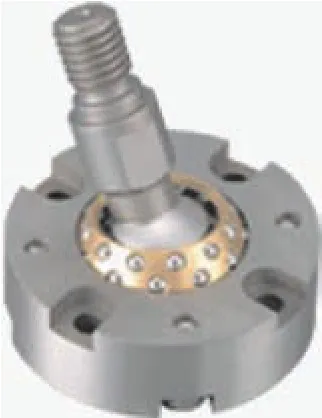
Fig.2 3-DOF gimbal.
2.2.Model
The dynamically similar model is mostly constructed with carbon fiber and the wing is made of carbon fiber–polymethacry limide foamscored sandwich structure.The model is an entirety construction except the moving control surfaces,the leading-edge flap is deflected with the connection piece in different angles,and the fore-body pitch control surface,elevon and rudder are driven by the actuators.A 105 mm×120 mm cutout in the model fuselage meets the requirement of operating range of the model rotation.The model’s mass characteristics,center of gravity,and moment of inertia parameter can be adjusted through the counterweights installed at different places in the model.The mass and inertia of moment are measured by special equipment.It is necessary to adjust the size and location of counterweights several times to satisfy the requirement of similar criterion.Facilitated in the design of the model is a 32 mm adjustment in the distance between the center of gravity and the aerodynamic center of the model.
The calculations according to the dynamical similar criterion,which is for mass,center of gravity location and inertia of moments at simulated altitude,are shown in Eqs.(1)–(3).The major parameters of the test model are provided in Table 1.
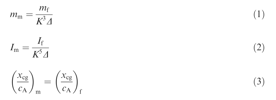
wheremmis the mass of test model,mfthe mass of the full-size aircraft,Kthe scaled ratio of the model,the air density ratio D¼qf=qm,qfthe air density at the simulated altitude,and qmthe air density at local altitude of wind tunnel.Imis the moment of inertia of test model,Ifthe moment of inertia of the full-size aircraft,xcgthe centre of gravity position along thex-direction,cAthe mean aerodynamic chord.The altitude above sea level of the selected wind tunnel is 650 m,qm=1.1504 kg/m3.
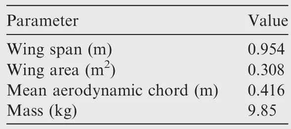
Table 1 Major parameters of test model.
2.3.Instrumentation and hardware

2.4.Test condition and procedure

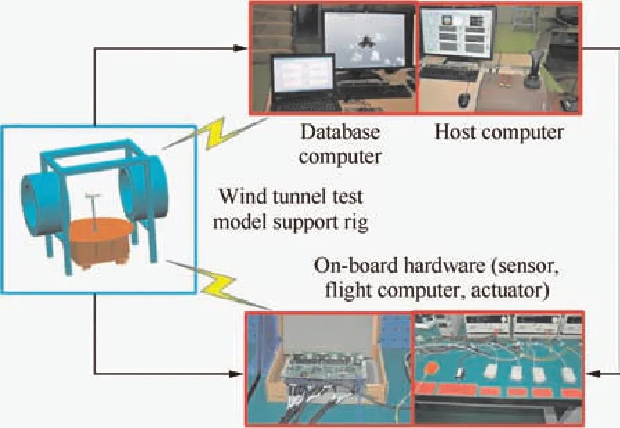
Fig.3 Schematic of virtual flight testing system.
The schematic of VFT system is shown in Fig.3.The diff iculties of system integration come from the total demand of small friction,physical simulation of multi-DOF maneuver,real time control,the generality and easy use.Each test begins with the aircraft model in a nearly zero-pitch condition.The facility operator brings the airflow velocity to the desired condition.The model operator starts to manipulate the control stick until the wind velocity is constant.The stick command is sent to the on-board receiver,which is used to transfer data to on-board computer via a serial driver board,through a wireless transmitter outside the tunnel.The servos’commands are formed by control law execution after combination of the feedback signals and control stick signals.The servos’commands are sent to drive the actuators through serial port communication.In this way,a closed circuit VFT testing system is formed to realize the stability and control of the free rotation model.The host computer is used for control stick signals acquisition,real-time feedback gain adjustment,state display,and flight parameter recording.The database computer is used for visual demonstration that is synchronous with the rotational model in wind tunnel.The host computer,database computer and on-board computer communicate with each other through wireless Ethernet.
We notice that there are several uncertain factors which could affect the test results.First,the time delay and free play at control surface,which are caused by aerodynamic and control linkage loads and friction,could affect the control performance.Second,the IMU and AHRS have specification with a high degree of accuracy,but their output signal is corrupted by electrical noise from the environment.Third,the strut interference introduces uncertain aerodynamic disturbance which affects the model and can lead to a steady state error.
3.Flight dynamics model and control law
3.1.Aerodynamic model
The source data is obtained from static and forced oscillation wind tunnel test conducted in£3.2 m wind tunnel in CARDC.The test data processing follows these steps:basic data education,interpolation,filling,and reference point transformation.Eventually,the aerodynamic moment database in three axes is constructed by increment method within the range of angle of attack and sideslip angle in VFT.The tunnel wall correction is performed in the mathematical model,while the interference from the support rig and the interference among the control surfaces are ignored.Take the total pitch moment coefficientCmas an example,and the detailed description is shown in Eqs.(4)–(6).

3.2.Dynamic model
The resultant acting on the model,which is namely the sum of gravity,aerodynamic force and bracing force from the support rig,is zero in virtual flight test because of the translational constrains.The dynamic equation is shown in Eq.(7).Oxbzbis usually a symmetry plane for ordinary airplane,soIxyandIyzequal zero in this situation.Eq.(7)can be simplified further.
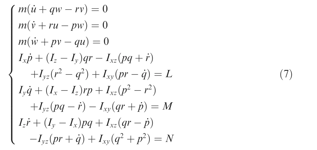
wheremis the mass of test model,Ix,Iy,Izare the inertia of three axes respectively,Ixz,Iyz,Ixyare the cross inertia,u,v,ware the velocity components in body axis system,p,q,rare the roll rate,pitch rate and yaw rate respectively,andL,M,Nare the moment components in body axis system.
The value and direction of velocity vector maintain constant during the virtual flight test,so the flow angle can be obtained from the attitude angle measured by the AHRS sensor.The calculation formula is shown in Eq.(8).a11,a21,a31are the first column elements of the matrix used to transform from ground coordinates system to body coordinates system.The angle of attack equals pitch angle when the rolling angle is zero.
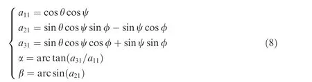
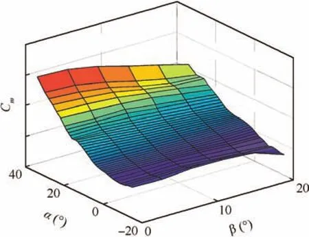
Fig.4 Pitch moment characteristics.
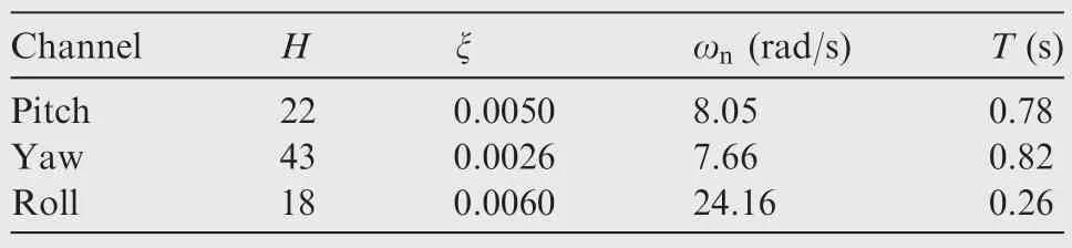
Table 2 Damping characteristics for 3-DOF gimbal.
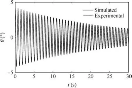
Fig.6 Friction characterization in model-pitch direction.
3.3.Friction effects
Related studies indicate that the friction effects should be evaluated before wind tunnel testing.The model is set up using a set of springs of known stiffness constant.The model starts to oscillate sinusoidally after initial excitation,and finally keeps stable at a certain position.The resultant motion is measured via the AHRS measurement sensor and recorded in the on-board computer.Estimates of the friction damping are then reduced from curve fitting an exponentially-decaying sine waveform to the data,as shown in Eq.(9).This procedure is repeated several times for all three model degrees of freedom to reduce the system error.
where n is the damping ratio,Hthe half-life oscillation times,Tthe period,x the frequency,xnthe natural frequency.
Table 2 summarizes the damping and natural frequencies obtained in pitch,roll and yaw directions.The yawing damping is about half of the other two directions,which is possibly related to the fact that the model c.g.is a little lower than the centre of the gimbal.The maximum damping is no more than 0.006,less than 1%of the aircraft model mode damping.The gimbal contributes a negligible amount to the overall damping of the system.The test data and fitted data for pitch channel are presented in Fig.6.The frequency and amplitude agrees well at initial phase,while there is a phase delay after 20 s.It needs to fine model for accurate fitting,such as bristle model.
3.4.Control law
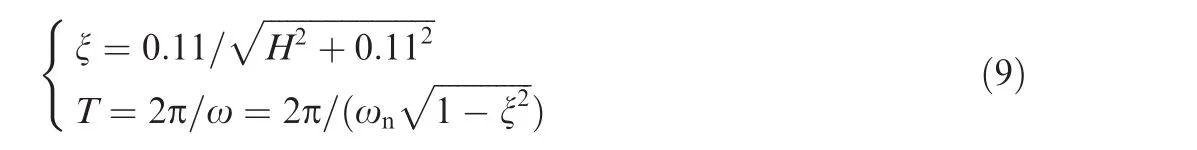
A control law is developed using a preflight aerodynamic model from which linearized state-space models are extracted.The feedback gains were chosen to provide sufficient damping and stability margins in all axes via root locus and Nichols graphical techniques.The schematic of control law is shown in Fig.7.It is pointed out that the control law parameters are obtained from the prototype aircraft according to the similarity law28;it is known that smaller model responds faster to attitude change,so the satisfaction of real-time control requirement is a challenge for the design of system’s hardware and software.A pitch rate command system is implemented for pitch-axis control augmentation system,which controls angle of attack when angle of attack exceeds a threshold value.Feedbacks to the longitudinal control law are pitch rate and angle of attack.These feedbacks provide damping and stabilization.Proportional integral(PI)controller is adopted to improve the accuracy.The function of the command model is command shaping,command limitation and stick input signal noise decaying.The control variable command is a function of displacement of the joystick.The command gradient is nonlinear in longitudinal axis.For small amplitude commands,the sensitivity is relatively low;for large amplitude commands,the sensitivity is relatively high.
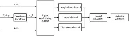
Fig.7 Schematic of control augmentation system.
The lateral and directional control law architecture used in this study is referred to as ‘p-b”-command,i.e.stability axes roll rate command in the lateral axis and sideslip command in the directional axis.Furthermore,the system controls the roll angle when roll angle exceeds a certain value.Feedbacks to the lateral control law are roll rate and roll angle.These feedbacks provide damping and limitation of roll angle.The command gradient is also nonlinear in lateral direction,just like longitudinal axis.Feedback signals in directional channel consist of three paths:yaw rate feedback,roll rate feedback,and sideslip angle limiter.These feedbacks provide damping,stabilization and limitation of sideslip angle.
The hardware in loop test(HILP)is conducted to validate the real-time performance of control law and flight control hardware before the wind tunnel test.The control stick,flight control computer and servos are real during the HILP simulation.An industry control computer,used to simulate the aircraft aerodynamic and dynamic model,transmits the flight parameter to flight control computer and also receives actuator command from flight control computer at the same time.
4.Simulation and test results
4.1.Longitudinal
The initial condition in the simulation corresponding to the testing start point is set to trim the model,and the handling history is kept the same as that of the test.The longitudinal dynamic response is contained in Fig.8,dmis the pitch stick position,dlis the roll stick position,dnis the pedal stick position,dvis the differential deflection of rudder.The operator’s handling histories are:stick back+neutral+stick forward+neutral+stick back+neutral,and the model pitches up to 18?angle of attack at which slight oscillation happened immediately after pulling stick;the peak value of pitch rate is up to 25(?)/s.The angle of attack goes back to 15?when the stick returns to neutral position.The model pitches down to?5?after stick is pushed forward;the peak value of pitch rate is?16(?)/s.When the stick returns to neutral position,the pitch attitude is kept at?5?.The model pitches up to 8?with small overshoot after stick is pulled again.The peak value of pitch rate is 32(?)/s.
The simulation and test results are compared,which show that the total tendency is consistent but the trimmed elevator has a 4.4?deviation.The reason is that theoreticalCm0is different from real situation.The data used in the simulation is obtained from the test in which rear sting support rig is employed,while the ventral support rig is applied in the virtual flight test.According to experience in the past,it has about 0.018 offset of pitch moment with the two support patterns.It is about 3?excursion calculated from the elevator effectiveness.Otherwise,simulation with the mathematical model considering nonlinear part such as the backlash and time lag could reproduce the observed oscillation at 2–4 s.The oscillation could be caused by not only the control surface clearance and system time delay,but also much higher longitudinal instability at this angle of attack region(15?–18?),which is shown in Fig.4.The backlash of the actuator and mechanical connecting rod can lead to the clearance of control surface.It is difficult to improve accuracy of servos on a scaled model.The time delay is caused by the wireless communication mode.If the wire communication mode is applied,the delay could be eliminated.
4.2.Lateral and directional
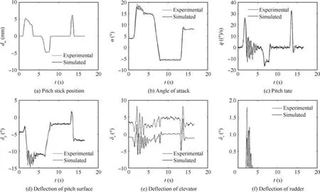
Fig.8 Pitch response comparative results.
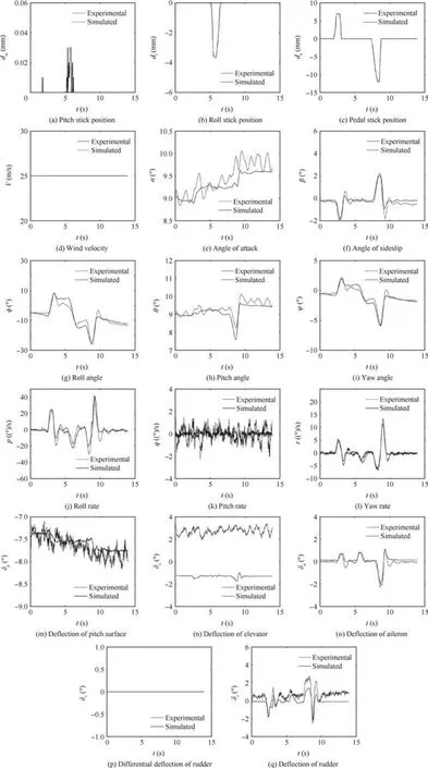
Fig.9 Lateral-directional response comparative results.
The time history of lateral and directional response is shown in Fig.9.The handling histories are:pedal right+neutral+stick left+neutral+pedal left+neutral.The nose turns to the right leading to?1.8?sideslip after pedal right operation.The negative sideslip provides the roll moment due to the lateral stability,so the model rolls to the right,and the peak value of roll rate is up to 24(?)/s.When the pedal goes back to neutral position,the yaw angle and sideslip angle go back to 0?,and the roll rate is back to nearly 0(?)/s.The model rolls left to about?11?after left action of stick.Analogously,the nose turns to the left and the model rolls left after left action of pedal;the peak value of roll rate is?30(?)/s.When the pedal goes back to neutral position,the yaw angle and sideslip angle go back to 0?,and the roll angle is back to about?12?.The angle of attack is kept at 9–10?during the manoeuver.The roll moment produced by feedbacks in the lateral channel,which can improve the roll damping and realize the limitation of roll motion,is opposite from the roll moment produced by the yaw handling.
The experimental results mostly agree well with the simulated results.There is a 3–5?deviation on rolling response when the pedal handling is finished,which is perhaps related to the control surface clearance and the model c.g.,shift relative to the gimbal reference point.There is a steady error on sideslip angle which leads to a deviation of the aileron and rudder after 10 s.Heading measurement using geomagnetic effect has lower accuracy than pitch/roll measurement using principle of the inertia.In other words,it indicates that the measured sideslip anglehasloweraccuracy than angleofattack from Eq.(8).Furthermore,thereisashiftofabout4?forthetrimmed elevator,and the reason is noted in the fore part.The amplitude of pitch rate is about±1.5(?)/s in the lateral test,while the amplitude is about±0.5(?)/s in the simulation.The difference is mainly caused by the IMU sensor noise,and itis found that it has a noise level of±1.0(?)/s during the electronic pretesting.
5.Conclusions
(1)The effect of stability augmentation and attitude control is verified in the virtual flight test.The test has demonstrated the capability of three-axis attitude control,and the feasibility of virtual flight test as platform for control law testing and evaluation is validated.The model can track the operator’s stick command well in the test,which is expected before the test.
(2)The response of pitch rate and angle of attack agrees well with the simulation results during the longitudinal wind tunnel test,and the deviation of angle of attack is less than 0.5?.There is a different trimmed elevator deflection because of the offset ofCm0.
(3)The response of roll rate and sideslip angle agrees well with the simulation results during the lateral and directional wind tunnel test,and the deviation of sideslip angle is less than 0.5?.
(4)The friction from 3-DOF gimbal is negligible for dynamic characteristics of aircraft model.The small amplitude oscillation during the test probably is related to the system time delay and mechanical clearance.This needs to be investigated further in the future.Otherwise,the capability of the test rig only can reach maximum angle of attack 30?at present;the test rig,dynamic model and control law need to be improved to extend the simulated range of angle of attack.
Acknowledgements
This study was supported by the National Key Basic Research Program of China(No.2015CB755800).
1.Wang Q,Qian WQ,He KF.Unsteady aerodynamic modeling at high angles of attack using support vector machines.Chin J Aeronaut2015;28(3):659–68.
2.Ratliff CL,Marquart EJ.An assessment of a potential test technique.Reston:AIAA;1995.Report No.:AIAA-1995-3415.
3.Ratliff CL,Marquart EJ.Bridging the gap between ground and flight tests:virtual flight testing(VFT).Reston:AIAA;1995.Report No.:AIAA-1995-3875.
4.Magill JC,WeHe SD.Initial test of a wire suspension mount for missile virtual flight testing.Reston:AIAA;2002.Report No.:AIAA-2002-0169.
5.Lawrence FC,Mills BH.Status update of the AEDC virtual flight testing development program.Reston:AIAA;2002.Report No.:AIAA-2002-0168.
6.Magill JC,Cataldi P,Morency JR,Hammer DX,Burgess R,Jeter E.Demonstration of a wire suspension for wind-tunnel virtual lf ight testing.J Spacecraft Rock2009;46(3):624–33.
7.Liu F,Wang LX,Tan XS.Digital virtual flight testing and evaluation method for flight characteristics airworthiness compliance of civil aircraft based on HQRM.Chin J Aeronaut2015;28(1):112–20.
8.Lowenberg MH,Kyle HL.Development of a pendulum support rig dynamic wind tunnel apparatus.Reston:AIAA;2002.Report No.:AIAA-2002-4879.
9.Pattinson J,Lowenberg MH,Goman MG.A multi-degree-offreedom rig for the wind tunnel determination of dynamic data.Reston:AIAA;2009.Report No.:AIAA-2009-5727.
10.Sen A,Bhange NP,Wahi P,Ghosh AK.5-degree-of-freedom dynamic rig for wind tunnel tests of aero-space vehicles.Reston:AIAA;2009.Report No.:AIAA-2009-5605.
11.Peyada1 NK,Ghosh AK,Go TH.Mathematical modeling,simulation,and estimation of aircraft parameters using five degree-of-freedom dynamic test rig.Proceedings of the institution of mechanical engineers.Xi’an:SAGE;2012.
12.Gatto A,Lowenberg MH.Evaluation of a three-degree-offreedom test rig for stability derivative estimation.J Aircraft2006;43(6):1747–62.
13.Gatto A.Application of a pendulum support test rig for aircraft stability derivative estimation.J Aircraft2006;46(3):927–34.
14.Pattinson J,Lowenberg MH,Goman MG.Multi-degree-offreedom wind-tunnel maneuver rig for dynamic simulation and aerodynamic model identification.J Aircraft2013;50(2):551–66.
15.Pattinson J,Lowenberg MH,Goman MG.Characterisation of wind tunnel observed,large-amplitude pitch limit-cycles.Reston:AIAA;2011.Report No.:AIAA-2011-6526.
16.Araujo-Estrada SA,Lowenberg MH,Neild S,Goman M.Evaluation of aircraft model upset behaviour using wind tunnel manoeuvrerig.Reston:AIAA;2015.Report No.:AIAA-2015-0750.
17.Sohi NP.Modeling of spin modes of supersonic aircraft in horizontal wind tunnel.24th congress of the international council of the aeronautical science;2004.
18.Davison PM,Lowenberg MH.Experimental analysis and modeling of limit cycles in a dynamic wind tunnel rig.J Aircraft2003;40(4):776–85.
19.Davison PM,Lowenberg MH.Modeling nonlinear behaviour in a single degree-of-freedom dynamic wind tunnel rig.Reston:AIAA;2003.Report No.:AIAA-2003-5314.
20.Richardson TS,Dubs A,Lowenberg MH,Jones C.Wind-tunnel testing of a dynamic state-feedback gain scheduled control system.Reston:AIAA;2005.Report No.:AIAA-2005-5976.
21.Khrabrov AN,Sidoryuk ME,Kolesnikov EN,Vinogradov YA,Grishin II,Kolinko KA.On possibility of critical flight regime study in wind tunnels using three-degree-of-freedom gimbals.TsAGI Sci J2014;45(8):825–39.
22.Grishin I,Khrabrov A,Kolinko A,Sidoryuk M,Vyalkov A.Wind tunnel investigation of critical flight regimes using dynamically scaled actively controlled model in 3-DOF gimbal.29th congress of the international council of the aeronautical science;2014.
23.Yuji M,Takeharu K,Masahiko S.Evaluation of self-repairing flight control system by wind-tunnel free- flight dynamic test.24th congress of the international council of the aeronautical science;2004.
24.Strub G,Theodoulis S,Gassmann V,Dobre S,Basset M.Pitch axis control for a guided projectile in a wind tunnel-based hardware-in-the-loop setup.Reston:AIAA;2015.Report No.:AIAA-2015–0153.
25.Stenfelt G,Ringertz U.Yaw control of a tailless aircraft configuration.J Aircraft2010;47(5):1807–10.
26.Xi K,Yuan W,Yan C,Huang Y.Virtual flight numerical simulation of the basic finner projectile with closed loop.Acta Aeronaut Astronaut2014;35(3):634–42[Chinese].
27.Zhao ZL,Wu JQ,Li H,Zhou WQ,Mao DY,Yang HY.Investigation of virtual flight testing technique based on 2.4 m transonic wind tunnel.Acta Aeronaut Astronaut2016;37(2):504–12[Chinese].
28.Guo LL,Zhu MH,Kong P,Nie BW,Zhong CW.Analysis of the dynamical characteristics between prototype aircraft and scaledmodel of virtual flight test in wind tunnel.Acta Aeronaut Astronaut2016;37(8):2583–93[Chinese].
29.Lee DK,Lee JS,Han JH,Kawamura Y.System identification and controller design of a micro air vehicle using magnetic suspension and balance system.Reston:AIAA;2011.Report No.:AIAA-2011-6401.
30.Huang M,Wang ZW.A review of wind tunnel based virtual flight testing techniques for evaluation of flight control systems.Int J Aerospace Eng2015;2015(1):1–22.
9 March 2016;revised 14 September 2016;accepted 19 October 2016
Available online 16 February 2017
*Corresponding author.
E-mail address:guolinliangliang@163.com(L.Guo).
Peer review under responsibility of Editorial Committee of CJA.
杂志排行

CHINESE JOURNAL OF AERONAUTICS的其它文章
- Dynamics of air transport networks:A review from a complex systems perspective
- ATM performance measurement in Europe,the US and China
- Network analysis of Chinese air transport delay propagation
- Robustness analysis metrics for worldwide airport network:A comprehensive study
- Evolution of airports from a network perspective–An analytical concept
- Methods for determining unimpeded aircraft taxiing time and evaluating airport taxiing performance