Effect of the PTO damping force on the wave pressures on a 2-D wave energy converter *
2017-11-02XuanlieZhao赵玄烈DezhiNing宁德志MalintemanHaiguiKang康海贵
Xuan-lie Zhao (赵玄烈), De-zhi Ning (宁德志),2, Malin Göteman, Hai-gui Kang (康海贵)
1. State Key Laboratory of Coastal and Offshore Engineering, Dalian University of Technology, Dalian 116023,China, E-mail: zhaoxuanlie@163.com
2. State Key Laboratory of Hydrology-Water Resources and Hydraulic Engineering, Hohai University, Nanjing 210098, China
3. Department of Engineering Science, Uppsala University, Uppsala, Sweden
(Received January 25, 2016, Revised March 21, 2017)
Effect of the PTO damping force on the wave pressures on a 2-D wave energy converter*
Xuan-lie Zhao (赵玄烈)1, De-zhi Ning (宁德志)1,2, Malin Göteman3, Hai-gui Kang (康海贵)1
1. State Key Laboratory of Coastal and Offshore Engineering, Dalian University of Technology, Dalian 116023,China, E-mail: zhaoxuanlie@163.com
2. State Key Laboratory of Hydrology-Water Resources and Hydraulic Engineering, Hohai University, Nanjing 210098, China
3. Department of Engineering Science, Uppsala University, Uppsala, Sweden
(Received January 25, 2016, Revised March 21, 2017)
The information of the wave loads on a wave energy device in operational waves is required for designing an efficient wave energy system with high survivability. It is also required as a reference for numerical modeling. In this paper, a novel system,which integrates an oscillating wave energy converter with a pile-restrained floating breakwater, is experimentally investigated in a 2-D wave flume. The measurements of the wave pressure on the wet-surface of the device are made as the function of the power take-off (PTO) damping force. It is shown that the wave pressure is significantly affected by the PTO system, in particular, at the edges, and the wave pressure varies under different wave conditions. From the results, conclusions can be drawn on how the PTO damping force and wave conditions affect the loads on the device, which is of engineering concern for constructing safe and reliable devices.
Wave energy converter, power take-off (PTO), wave pressure, experimental measurement
Introduction
Even with an advanced power take-off (PTO)system that changes in time, a constant ratio between the PTO damping force and the wave excitation force is not realizable in the realistic sea states[1]. During a routine operation in moderate sea states, the wave energy converters (WECs) are under the impact of cyclic wave loads, which is an important issue for the construction of safe WECs[2]. The dynamical wave force on a floating body includes two parts: the wave excitation force and the radiation force[3]. Generally,the wave forces on a heaving wave energy device(coupled with the PTO damping force) is different from that on a freely floating buoy of identical geometry, since the radiation force is closely related to the heave response amplitude of the floating buoy.Hence, it is meaningful to investigate the variation of the wave loads on the devices as a function of the PTO damping force. It is perhaps surprising that a detailed experimental data of the variation of the wave pressure loads on the floating buoy as a function of the extra PTO damping force is not readily available in the literature. The wave pressure at different positions of the buoy is the input in designing a device and evaluating the structure fatigue and life-expectancy. It is the intention of this paper to provide experimental data obtained under the action of welldefined moderate regular waves, and to evaluate the accuracy of the hydrodynamic model of the device.
The floating device studied in the paper is constrained to oscillate in heave by a vertical pile. The base structure of the WEC can be used as the floating breakwater, and the construction-cost sharing can be achieved with the cost-effective generation of electricity from the waves[6]. Indeed, in recent years, several concepts were proposed, where the wave energy converters were integrated into the design of a breakwater have emerged[4-7]. The present study gives a new configuration, for which the so-called dual function(the wave attenuation performance and the wave energy utilization) can be realized, under the principle of an oscillating buoy wave energy converter. For thebase structure, the study of the wave loads on the rectangular box, as a common marine structure, attracts much attention in view of different applications,such as Shi et al.[8], Li and Lin[9], Diamantoulaki et al.[10], Koutandos[11]and Chen et al.[12]. For the heaving point-absorbing WECs, the PTO damping force was found to affect the wave loads on the device to a great extent[13,14], and the variation of the wave loads as a function of the PTO damping force was also found to be meaningful for other wave energy devices.The effect of the PTO damping force on the wave pressure loads can also play a vital role in improving the survival characteristics.
1. Experiment
1.1Experiment description
The experiment is carried out in a flume in the State Key Laboratory of Coastal and Offshore Engineering, Dalian University of Technology, China. The flume is 69 m long, 2 m wide and 1.8 m deep. A piston-type unidirectional wave-maker is installed at one end of the flume, and a wave-absorbing beach is located at the other end to reduce the wave reflection.A wall is installed along the longitudinal direction of the wave flume to divide the width of the flume into two parts: the part of 1.2 m width and the part of 0.8 m width, where the part of 0.8 m width is selected as the test section. A floating breakwater of rectangular cross-section is chosen as the base structure. A 1:10 scale model is constructed based on the Froude scaling. The model is 0.78 m long (along the direction perpendicular to the incident wave), 0.8 m wide and 0.6 m in height (as shown in Fig.1(a)). In order to avoid unnecessary friction and possible collisions, a 0.01 m gap is set between each side of the floating breakwater and the flume wall, and the two gaps are checked after each experiment. The integrated system consists of a floating breakwater connected through a rack-gear transmission mechanism to a power take-off system installed above the breakwater. A slide rail (as shown in Fig.1(b)) is used as the vertical pile, which restrains the floating breakwater to a pure heave motion. Two pulleys (as shown in Fig.1(b)) are used to connect the floating breakwater with the vertical pile, with the friction coefficient between the pulley and the slide rail of 0.035 (determined in a friction coefficient measurement test). The power take-off system is modeled physically by a current controllermagnetic p owder b rake system. To ensure the accuracy of thedata, allexperiments areperformedthree times, and the average is taken.
The following parameters are used in the experiments: the static water depthh= 1.0m, the draft of the floating breakwaterd=0.25m , and the incident wave heightHiis kept as a constant of 0.2 m. To simulate the wave periods of 4 s-7 s in the real sea state, four wave periodsTin the range of 1.37 s-2.42 s are investigated in the experiment. For the floating breakwater, the range of the non-dimensional relative widthB/L(whereBis the width of the device a(Knd o u tLa ndtohse e w t a aveleng. th T)huos f, 0B.1 = -0 0..38 mis o isf aidnot ep rtee sdt and the value ofB/Lvaried from 0.12 to 0.28 (as shown in Table 1) according to the selected wave periods. According tothe optimumdamping of thebase structure (Ning et the excitation currentI, which represents the value of the PTO damping force, is selected in the range of 0-0.30 A with an interval of 0.06 A. The test conditions are shown in Table 1.

Fig.1 (Color online) Dimensions of FB model and a view of the pulley and the slide rail

Table 1 Test conditions. (The ratio /BL is derived fromthedifferent wave periodsT tested, the parameter forthecucurrent I is independent and represents the PTO damping force)
1.2Data acquisition system and data analysis
The absorbed power and the PTO damping force can be recorded by a power-torque sensor, and two gauges are arranged on the front side and the leeside of the floating breakwater to collect the data to be used for calculating the reflection coefficient (Kr)and the transmission coefficient (Kt), respectively.Seven pressure sensors are used to measure the wave pressure (p) on the wet-surface of the floating breakwater. The detailed locations of the pressure sensors are shown in Fig.2. The heave motion of the floating breakwater is measured by using a noncontact displacement measurement system. The ratio between the height of the heave motion (Hheave) and the incident wave height,ζ=Hheave/Hi, indicates the system response to the incident waves. The validation of the experimental design in terms of the th reaing shmt irsastiioo n wco ase ff ciocni ed nu tc taendd bt hy e Nhien ag v ee-tin ciden, t wwh ai v che paves the way for the present study.

Fig.2 Detailed positions of the pressure measuring points (repre- sented by black circles)
Due to the high frequency noise from the pressure sensor, the measurement results are filtered using a low pass FFT filter, in which the frequency cutoff percentage of 10 is adopted. Figure 3 gives the typical measured and filtered time series of the wave pressure, which shows that the present filtering method could effectively remove the noise.
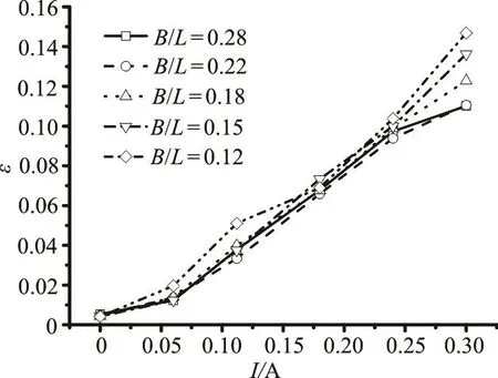
Fig.4 Time-averaged PTO damping force under each conditions of d /H=0.25

Fig.5 Time series of outputted PTO damping force under typi- cal conditions of B /L = 0.18,d /H =0.25
2. Experimental results
2.1Characteristics of the PTO damping force
The PTO damping force is studied firstly. The relative PTO damping force ()εis a non-dimensional PTO damping force, defined as the ratio between the outputted time-averaged PTO damping force and the vertical exciting force (obtained by an analytical method based on the linear potential theory[16]) acted on the device. The relative PTO damping forces under each working condition are shown in Fig.4. Eight wave periods are adopted to calculate the time-averaged PTO damping force. As a particular case, Fig.5 shows the time series of the damping force, which indicates that the Coulomb damping force can be exactly obtained for cases ofI≥ 0 .18A and approximately for others. Note that,since a small friction always exists in the magnetic powder system, the damping force is non-zero. The power-torque sensor can capture the friction force and the power generated by the intrinsic friction. In the case of a hydraulic PTO, a Coulomb damping model is often used. Different from the linear damping force,the remarkable feature of the Coulomb damping force is that the magnitude of the damping force is constant and its direction is only related with the device movement. The approximate Coulomb damping force is a slight modification of the perfect Coulomb damping force (the details can be found in Babarit et al.[18]). Thus, the experiment may provide an important input for the Wave-2-Wire model.
2.2Wave pressures on the seaward and leeward surfaces
Figures 6-10 show the time-series of the nondimensional wave pressure at positions 1# and 7#,located on the seaward and leeward surfaces, respectively, as shown in Fig.2. The vertical coordinate refers to the non-dimensional wave pressure by dividing the measured wave pressurepby the hydrostatic pressure0ghρ(where is the water density, the gravitational acceleration and0hthe distance to the static water surface).

Fig.6 Time series of wave pressure for the case of B /L =0.28

Fig.7 Time series of wave pressure for the case of B /L =0.22
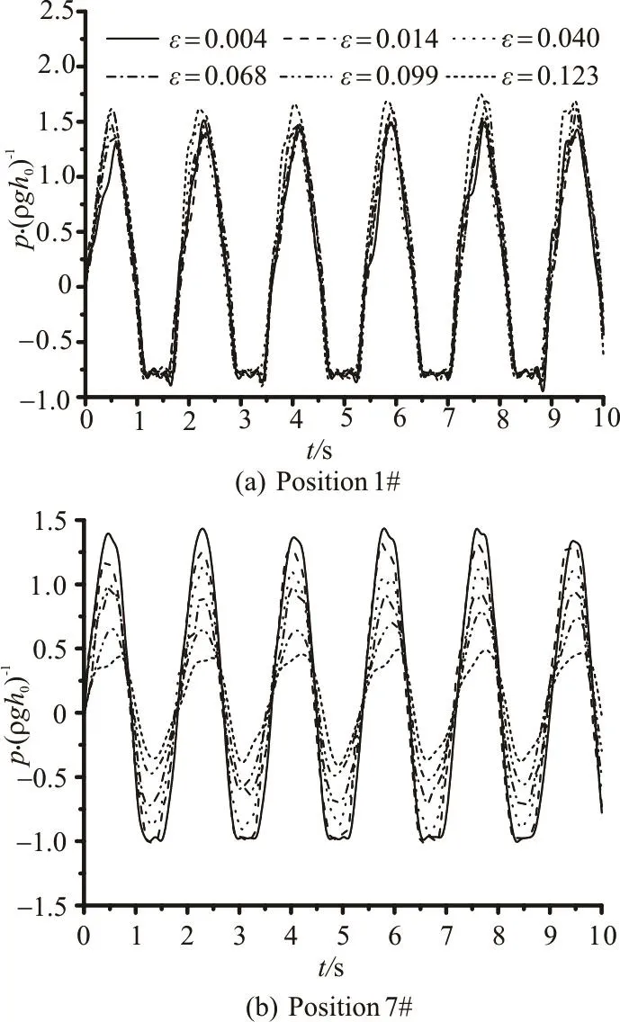
Fig.8 Time series of wave pressure at for the case of B /L= 0.18

Fig.9 Time series of wave pressure for the case of B /L =0.15
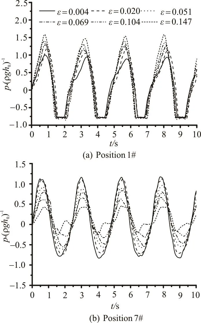
Fig.10 Time series of wave pressure for the case of B /L =0.12
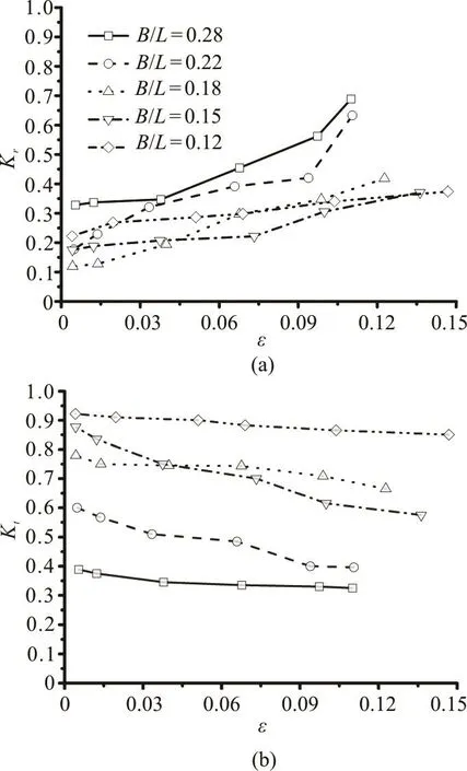
Fig.11 Results of reflection coefficient (Kr ) and transmission coefficient (Kt)
From Figs.6-10, we can see that the PTO damping force has a significant effect on the wave pressure loads (at positions 1# and 7#) for the tested rela tive widthsB/L. But the varia tio n tendency of thenon-dimensionalwavepressureasafunction of the PTO damping force is different for different /BL.For cases of /=BL0.22 and 0.28 at position 1#, the wave pressure decreases with the increase of the PTO damping force. Conversely, for cases of /=BL0.12,0.15 and 0.18, the wave pressure increases slightly with the increase of the PTO damping force at the same position. This is probably due to the fact that for the present 2-D experiment, there are standing waves formed in the front of the breakwater (this phenomenon was verified by Koutandos et al.[15]). From Fig.11(a) we can see that the reflection coefficient increases drastically with the increase of the PTO damping force, which may imply that the effect of standing waves becomes more prominent when the floating device is under the action of short period waves, i.e., 0.22 <B/L< 0 .28. Thus, the wave amplitude in the region close to the front wall of the floating breakwater is decreased relatively. However,when the floating breakwater is under the action of relatively longer waves, there are no standing waves formed and the reflection coefficient increases with the increase of the PTO damping force, which leads to a larger wave amplitude. Then the wave pressure increases accordingly.

Fig.12 Results of heave RAO for tested cases
At the position 7#, the wave pressure loads dethe back wall is closely related to the relative motion between the floating breakwater and the waves formed on the leeside. The transmission coefficient in Fig.11(b) shows that the transmitted waves on the leeside decrease slightly with the increase of the PTO,which could explain the decrease in the wave pressure.Also, the decrease of the heave response amplitude with the increase of the PTO damping (Fig.12) could add to this effect.crease with the increase of the PTO damping force for all tested relative widths /BL. The wave pressure on
2.3Wave pressures on the bottom surface
Figures 13(a)-13(e) show the results of the nondimensional wave pressure amplitude at the positions 2#-6# on the bottom of the floating breakwater, as in Fig.2. As previously mentioned, the hydrostatic componentgdρ(wheredis the draft), is subtrac-ted from the recordings and the vertical coordinate refers to the non-dimensional wave pressure amplitude defined as the wave pressure amplitudeApdivided by gdρ.

Fig.13 Wave pressure amplitude at positions 2#-6# for all tested relative widths
As can be seen from Figs.13(a)-13(e), the PTO damping force affects the measured wave pressure, in particular, at the positions close to the front and back edges of the float. From Fig.13(a) we can conclude that the variation tendency of the wave pressure at position 2# is similar to that at position 1#, as expected due to the close proximity of the two positions. The wave pressure amplitude decreases with the increase of the PTO damping force for /=BL 0.28 and 0.22, conversely, for cases of B /L < 0 .22, the wave pressure increases with the increase of the PTO damping force.
At positions 3# and 4#, on the middle section of the bottom on the up-wave side, the wave pressure loads are increasing slightly with the damping force for the tested five relative widths.
Interestingly, at positions 5# and 6#, on the middle section of the bottom on the down-wave side,the wave pressure decreases with the increase of the damping force up to the point of =0.10ε, after which it increases.
From Figs.13(b)-13(e), we also conclude that the measured wave pressure is smaller at positions closer to the middle of the bottom, and that the wave periods affect the pressure to a smaller extent. This may be due to the more complex flow field and vortices at the edges.
3. Discussions
At the front position 1#, the pressure time series are periodic, but not simple harmonic periodic. This can be due to the fact that the waves formed on the front side of the floating box is the superposition of the incident waves and the reflection waves, and the waves formed on the leeside is the transmitted waves.Obviously, the wave amplitude on the front side is larger than that on the leeside. This may be due to the fact that the position 1# can heave out of the waves and the position 7# will not. So the pressure time series at the position 1# are not simple harmonic periodic.
The position 6# is close to the back wall, thus,the wave pressure here is inclined to be affected by the waves on the leeside of the breakwater, and follows a similar trend as that at the position 7# for the PTO damping 0.10ε<. However, the pressure increases slightly after =0.10ε. At the position 5#, the same trend occurs but to a smaller extent. This behavior at the positions 5#-6# can possibly be attributed to the vortices which may dominate the flow field, and which are stronger near the position closer to the back edge. The positions close to the front edge do not show a similar parabolic trend, since the normal pressure caused by the incident potential, the diffracted potential and the radiation potential dominate the total pressure, even though the vortex strength is larger than that at the positions close to the edge of back wall[19].
Göteman et al.'s study[13]indicates that the measured force in the mooring line of the heaving wave energy converter system is effectively reduced with the increased PTO force. In the present study, the wave pressure shows a more complex behavior as a function of the PTO damping force. Due to the different setups of the two experiments, a direct comparison is not possible: a 2-D experiment in this study and a 3-D experiment in Göteman et al.[13], the geometry of the WEC in this study is a rectangular box and that in Göteman et al.[13]is a circular cylinder.Further, the measured force in the mooring line is a total force which is equals to the integration of the pressure on the surface, whereas in the present experiment the wave pressure is measured directly at chosen positions of the wet-surface. Nevertheless, both papers show that the wave loads are affected by the PTO damping, which is an important conclusion to consider when designing a WEC.
From the point of view of engineering applications, the variation of the wave pressure loads at each position shall be measured to prevent the structural damage. As seen in the previous section, the wave pressure at locations close to the edges are of particular importance, the dependence of the PTO damping force and different wave periods is more complex, and the maximum value of the wave pressure amplitude is relatively higher.
The test is conducted in a 2-D wave flume and the 3-D effects cannot be taken into account. The 2-D hydrodynamic problem is different from the 3-D problem even though the studied object is a long structure in terms of the longitudinal direction perpendicular to the dominating wave direction[20]. This paper serves as a study of the wave loads as a function of the PTO damping in operational waves, which gives insight into important design parameters and verifies the model for further studies. In the future studies, the effect of the PTO damping force on the wave loads will be investigated for a 3-D problem in both operational and extreme waves.
4. Conclusions
A 1:10 scale model test of a pile-restrained floating breakwater is conducted in a wave flume,under the principle of an oscillating buoy wave energy converter. The wave pressure is measured on the front wall, the back wall and the bottom for different waves,corresponding to relative widths / =BL 0.12, 0.15,0.18, 0.22 and 0.28, where B is the width of the device and Lthe wavelength. The experimental results show that the influence of the PTO damping on the wave pressure is different at different positions of the wet-surface. The wave pressure is affected by the damping force most significantly on the front and back walls. For short period waves (/=BL 0.22, 0.28),the wave pressure on the front and back walls decreases with the increasing PTO damping force.However, for longer period waves (/=BL 0.12, 0.15 and 0.18), the wave pressure on the front increases with the increasing PTO damping force, whereas it decreases on the back. The measured wave pressure is the smallest on the middle section of the bottom, and increases slightly with the increasing PTO damping force. The wave pressure close to the back sees a rather complex behavior, with the decreasing pressure up to a certain PTO damping, after which the measured pressure increases.
Acknowledgement
This wotk was supported by the Royal Academy of Engineeringunder theUK-China Industry Academia Partnership Programme(Grant No.UK-CIAPP/73), the Open Fund of State Key Laboratory of Coastal and Offshore Engineering, Dalian University of Technology.
[1] Henderson R. Design, simulation, and testing of a novel hydraulic power take-off system for the Pelamis wave energy converter [J]. Renewable Energy, 2006, 31(2):271-283.
[2] Yao Q., Wang S. M., Hu H. P. One the development and prospect of wave energy power generation device [J].Ocean Development and Management, 2016, 33(1): 86-92(in Chinese).
[3] Newman J. N. Marine hydrodynamics [M]. Cambridge,USA: MIT Press, 1977.
[4] Michailides C., Angelides D. C. Modeling of energy extraction and behavior of a flexible floating breakwater[J]. Applied Ocean Research, 2012, 35(1): 77-94.
[5] Arena F., Romolo A., Malara G. et al. On design and building of a U-OWC wave energy converter in the Mediterranean Sea: A case study [C]. Proceedings of the International Conference on Offshore Mechanics and Arctic Engineering-OMAE. Nantes, France, 2013, V008T09A102.
[6] He F., Huang Z. H. Hydrodynamic performance of pilesupported OWC-type structures as breakwaters: An experimental study [J]. Ocean Engineering, 2014, 88:618-626.
[7] Chen B., Liu C. Q., Kang H. G. Performance of floating breakwater double used as wave energy converter [C].Proceedings of the International Offshore and Polar Engineering Conference. Hawaii, USA, 2015, 888-892.
[8] Shi Q., You Y. X., Wei G. et al. The wave forces and moments on a floating rectangular box in a two-layer fluid [J].Journal of Hydrodynamics, Ser. B, 2006, 18(3): 166-170.
[9] Li Y., Lin M. Wave-current impacts on surface-piercing structure based on a fully nonlinear numerical tank [J].Journal of Hydrodynamics, 2015, 27(1): 131-140.
[10] Diamantoulaki I., Angelides D. C., Manolis G. D. Performance of pile-restrained flexible floating breakwaters [J].Applied Ocean Research, 2008, 30(4): 243-255.
[11] Koutandos E. V. Pontoon breakwaters-efficiency and loads-effect of attached plate layout[J]. International Review of Civil Engineering, 2010, 1(2): 143-153.
[12] Chen L., Sun L., Zang J. et al. Numerical study of roll motion of a 2-D floating structure in viscous flow [J]. Journal of Hydrodynamics, 2016, 28(4): 544-563.
[13] Göteman M., Engström J., Eriksson M. et al. Wave loads on a point-absorbing device in extreme waves [J]. Journal of Ocean and Wind Energy, 2015, 2(3): 176-181.
[14] Zhang X. T., Yang J. M., Xiao L. F. An oscillating wave energy converter with nonlinear snap-through powertake-off systems in regular waves [J]. ChinaOcean Engineering, 2016, 30(4): 565-580.
[15] Koutandos E. V., Prinos P., Gironella X. Floating breakwaters under regular and irregular wave forcing-reflection and transmission characteristics [J]. Journal of Hydraulic Research, 2005, 43(2): 174-188.
[16] Ning D., Zhao X., Göteman M. et al. Hydrodynamic performance of a pile-restrained WEC-type floating breakwater: An experimental study [J]. Renewable Energy,2016, 95: 531-541.
[17] Li Y. C., Teng B. Wave action on maritime structure [M].Beijing: China Ocean Press, 2015(in Chinese).
[18] Babarit A., Hals J., Muliawan M. J. et al. Numerical benchmarking study of a selection of wave energy converters [J].Renewable Energy, 2012, 41: 44-63.
[19] Koftis T. H., Prinos P., Koutandos E. V. 2D-V hydrodynamics of wave–floating breakwater interaction [J]. Journal of Hydraulic Research, 2006, 44(4): 451-469.
[20] Isaacson M., Nwogu O. U. Wave loads and motions of long structures in directional seas [J]. Journal of Offshore Mechanics and Arctic Engineering,1987,109(2):126-132.
* Project supported by the National Natural Science Foundation of China (Grant No. 51379037).
Biography: Xuan-lie Zhao (1989-), Male, Ph. D. Candidate
De-zhi Ning,E-mail: dzning@dlut.edu.cn
猜你喜欢
杂志排行

水动力学研究与进展 B辑的其它文章
- On the clean numerical simulation (CNS) of chaotic dynamic systems *
- BEM for wave interaction with structures and low storage accelerated methods for large scale computation *
- Flow-pipe-soil coupling mechanisms and predictions for submarine pipeline instability *
- Simulation of flows with moving contact lines on a dual-resolution Cartesian grid using a diffuse-interface immersed-boundary method *
- On the hydrodynamics of hydraulic machinery and flow control *
- A 3-D SPH model for simulating water flooding of a damaged floating structure *