Structural Optimization of Containership Based on a 2D Hydroelasto-plasticity Method and Ultimate Strength Evaluation
2017-06-22LIUWeiqinSONGXueminWUWeiguoSUZUKIKatsuyuki
LIU Wei-qin,SONG Xue-min,WU Wei-guo,SUZUKI Katsuyuki
(1.Departments of Naval Architecture,Ocean and Structural Engineering,School of Transportation,Wuhan University of Technology,Wuhan 430063,China;2.Department of Systems Innovation,Graduate School of Engineering,the University of Tokyo,Tokyo 113-8656,Japan)
Structural Optimization of Containership Based on a 2D Hydroelasto-plasticity Method and Ultimate Strength Evaluation
LIU Wei-qin1,SONG Xue-min1,WU Wei-guo1,SUZUKI Katsuyuki2
(1.Departments of Naval Architecture,Ocean and Structural Engineering,School of Transportation,Wuhan University of Technology,Wuhan 430063,China;2.Department of Systems Innovation,Graduate School of Engineering,the University of Tokyo,Tokyo 113-8656,Japan)
Generally,extreme waves used to lead to ultimate collapse of ship structure,actural ultimate collapse involves the dynamic ultimate strength and structural nonlinearity of ship.In this paper,a 2D hydroelasto-plasticity method is used as a means of studying the nonlinear dynamic strength of a containership in extreme waves,while considering the ultimate strength of the ship. The hydroelasto-plasticity is able to consider the coupling of ship structural nonlinearity and waves. The structural optimization of a containership is studied by using the 2D hydroelasto-plasticity method to carry out ultimate strength evaluation.Sequential quadratic programming(SQP)method is used to optimize the structural members of the containership based on nonlinear dynamic ultimate strength. The least structural cost is objective function,constraint condition is that structural strength is thought to be smaller than ultimate strength,and the structural size of each structural members should be satisfy with the CSR.As the extreme wave height is changed,the tendency of optimal design variables is discovered.Several studying conclusions can be referred by rules of ship classification.
nonlinear dynamic strength;ultimate strength;hydroelasticity; hydroelasto-plasticity;structural optimization;SQP;containership; extreme wave
0 Introduction
Many researchers have been pursuing a means of developing an efficient and accurate method to evaluate the ultimate strength of hull girders.Most approaches to computing ultimate strength were based on quasi-static methods.However,some accidents involving ships have resulted from an encounter with an extreme wave.Therefore,it is the latest trend to study the relationship and coupling between the nonlinear dynamic strength of a ship and extreme waves or other giant waves.
‘Extreme waves’are precisely defined as waves with a single height more than twice thesignificant wave height.Peliniovsky et al[1]cataloged major marine accidents around the world, and found that at least 22 super-carriers had been lost because of encounters to extreme waves between 1969 and 1994,causing 525 fatalities.He performed several computations of wave loads encountered in the Pacific and the Atlantic.Muller et al[2]described Norwegian Wilstar tanker was hit by an extreme wave at South Africa Sea in 1974,and the bow of tanker was severely damaged.Yang et al[3]recorded an accident of 24th-A platform at Ekofisk oil field damaged by an extreme wave,the wall of control room of the platform was destroyed by the wave with average wave height above 20 m.

Traditional hydroelastic theory cannot model the nonlinear structural response of a ship in extreme waves,and the most popular static methods for calculating the nonlinear strength of a ship do not address the dynamic wave problem.It is the latest trend to study the coupling problem by using hydroelasto-plasticity method.Iijima et al[7]proposed a hydroelasto-plasticity method for a model test,whereby two rigid segments are connected by plastic hinges of different rigidities,the rotational angle at a midship section.The actual ship structure collapse due to an extreme wave was not addressed in their study.Liu et al[8]used a strip code to calculate the wave loads of containership when it transversed in extreme waves,and then these wave loads were applied on nonlinear dynamic FEM model to obtain nonlinear dynamic VBM and angles at midship.Liu et al[9]proposed a 2D hydroelasto-plastic method to evaluate ship nonlinear dynamic strength of ship beam in extreme waves,regarding ship structure as a pure elasto-plastic beam with sulciform section,no buckling effect of ship girder is considered while Liu et al[10]later considered the interaction and coupling between in ship structure and waves, a simplified progressive collapse method taking the buckling effect of ship structure into account is combined with the 2D hydroelasto-plasticity method.This paper would use the same 2D hydroelasto-plasticity method to calculate the nonlinear dynamic strength of containership as evaluation role to define structural optimization of the containership.
It is an important and complicated course to design ship structure.It is extremely costly to build such large and complicated structure,the economic benefit is very dependent on structural design program,with the arrival of resource-conserving times,it is the trend of the times to save resource and ship building material,it is necessary to perform ship structural optimization.Jufuku et al[11]used a Sequential Quadratic Programming method(SQP)to optimize a structure of box girder and a oil tanker to obtain the minimized life cost of ship including steelcost,manufacturing cost,outfitting cost,and maintaining cost.And renewing cost of steel material due to corrosion is addressed.Okada et al[12]studied the optimization methods to optimize ship structural design and drafting.Initial cost involving steel cost and manufacturing cost is considered as objective function to optimize structure.A double oil tanker is optimized in initial design.Forgoing optimization researches used to be performed for linear ship strength optimization that maximum strength should be smaller than yield strength or allowed strength, as a result that ship structural plastic strength is underevaluated and steel material may be lavish.It is necessary to consider ship structural optimization based on ultimate strength evaluation.
International Association of Classification Societies attached importance to resent ship safety,Common Structural Rules(CSR)is formulated.The minimized structural size of ship structural members should be satisfied with CSR.
Therefore,this study differs from previous hydroelasto-plasticity researches,in that an actual containership was too studied to determine its ultimate strength when traversing extreme waves.The same hydroelasto-plastic method is capable of considering the ultimate strength of containership in extreme waves.A number of extreme wave parameters such as maximum wave height and wave speed are changed to study the dangerous extreme wave condition,and then determine most sensitive factor of wave parameter.By changing the most sensitive factor of wave parameter,the nonlinear structural optimization based on ultimate strength is performed for the containership.
1 Theoretical background
1.1 Overview
The hydroelasticity method is used to solve the elastic response of a ship’s structure when traversing waves.However,hydroelasticity cannot compute the dynamic nonlinear structural response of a ship when faced with an extreme wave.The hydroelasto-plasticity method proposed by Liu et al[10]used a simplified progressive collapse method(Smith method)providing a simple but efficient method for analyzing the progressive collapse behavior of a ship’s girder structures under vertical bending,allowing the static ultimate strength to combine hydrelasticity theory.This method considers the plasticity and buckling nonlinearity of a ship’s section.The rigidity and modal shape displacement of a ship’s girder,which are dependent on the deformational curvature,can be a variable rather than constant values in hydroelastic theory,allowing a nonlinear dynamic strength and large deformation to be obtained.The same hydroelasto-plasticity method as Liu et al[10]is adopted to solve the nonlinear dynamic strength and large deformation of a containership,and then a nonlinear structural optimization of the containership is performed on account of ultimate strength by using SQP method.
1.2 2D hydroelasticity theory
A ship can be modeled as a non-uniform free-free beam,and is often assumed to be aBernoulli-Euler beam.A right-handed coordinate system O( x0,y0,z0)is fixed in space.The(x0,y0)plane corresponds to the surface of the water, and Z0is directed downwards.Another right-handed coordinate system O(x,y,z)moves forward at a constant speed U,equal to the speed of the ship,and the origin o coincides with a point on the surface of the water, dropped perpendicularly from the aft of the ship.Here,x corresponds to the forward motion of the ship and z is vertically downwards.At the initial time t=0,the two coordinate systems coincide.In terms of the incident waves,it was first considered that a regular wave with an amplitude of ζ0propagates in the negative x direction.Fig.1 shows the coordinate system of the 2D hydroelasto-plasticity method. For an infinitesimal segment,dx,we can apply the following equilibrium formula.


Fig.1 Coordinate system of the 2D hydroelastoplasticity method
where M is vertical bending moment;F is shear force;feis external force;m is mass per unit length of ship;and w is vertical deflection including elastic-plastic and rigid deflection.Moreover,the vertical bending moment M can be expressed as

where η is equivalent structural damping coefficient;E is Young’s modulus;and I is section moment of inertia.The product term EI is called the‘rigidity of the ship’.Substituting Eq.(2) into Eq.(1),gives Eq.(3),as follows:

Eq.(3)defines the hydroelastic formula equilibrium.Here,the external force feincludes the wave damping force fr,the weight of the ship fg,the restoring force fs,and the hydrodynamic force fm′.

here,the hydrodynamic force fm′takes the hydrodynamic effect of a wave on the ship into account.Even extreme wave,this force remains dominant.Yamamoto et al[5]derived the hydrodynamic force equation presented in Eq.(5).This takes the slamming effect and wave nonlinear-ity into account.

where MHis added mass derived by the boundary element method,Eq.(5)includes the slamming force component,fslam.

The second part of the hydrodynamic force is the damping force,which is proportional to the speed V:

The restoring force is given by the following equation:

The inertial force is given by the following equation:

where W(x)is the weight per unit length.
The force of the ship’s weight due to gravity is expressed as follows:

In addition,the hydroelasto-plasticity method combines the progressive collapse method with hydroelastic theory.The quasi-static method is used to determine the structural section bending moment and rigidity.The rigidity is determined from the following equation:

where EIpis the nonlinear rigidity,Mpis the nonlinear elastic-plastic bending moment,and w″is the curvature of the section.The relationship between the rigidity and the curvature is determined by using the progressive collapse method.Moreover,as the rigidity changes,the natural modal shape can be calculated to obtain the renewed vertical deflection wp.The vertical deflection wpshould be satisfied with a boundary condition of free-free.This is expanded by superposing a series of the structural natural modal shape.

The angle deformation can be addressed by using differential equation of global deflection wp.
The beam rigidity is reduced to consider its capacity to resist deformation under the influence of an extreme wave,so that modal superposition can be applied to a beam model with 2D hydroelasto-plasticity.The dynamic rigidity,EIp,which is related to the curvature and modified modal shape,is substituted into Eq.(3).

Substituting Eq.(12)into Eq.(3)gives a dynamic modified hydroelastic equilibrium formula,as given by Eq.(14).This gives the plastic effect,and the added mass and wave-damping coefficient are obtained by using the 2D finite boundary element method.

Eq.(15)involves the term of inertia force matrix[M],the term of damping force matrix[C], the term of stiffness force matrix[K]and the term of external force matrix[F].Once the initial conditions are set,the increments can be obtained for a time series by using a numerical integration scheme such as the Newmark β method.
1.3 Sequential Quadratic Programming(SQP)method
Sequential Quadratic Programming(SQP)is used to consider nonlinear constrained optimization problem as follows:

SQP is an efficient optimal method to solve nonlinear constraint problem.Its principal solving means that descending direction is determined to solve a sequential quadratic programming subproblem in each step,so the objective function is reduced to obtain iterative step, and repeats these procedures to get the solution of optimal problem.
A given point(xk,μk,λk)is determined,and then the constrained function is linearized. Lagrangian function is approximated a quadratic polynomial,a quadratic programming subproblem is obtained.
Lagrangian function is presented as follows:

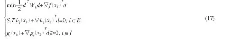
So the modification step of iterative point xkand renewed the estimation of Lagrangian multiplier μk+1,λk+1are addressed as optimal solution d*and responding Lagrangian multiplier μ and λ which are defined in Eq.(17).
Constraint optimal problem is explained in Eq.(16)at the iterative point(xk,μk,λk),SQP needs to construct a quadratic programming subproblem as follows:
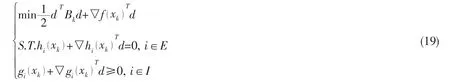
The solution of such quadratic programming subproblem is addressed to search the direction of original variable x at the k-th iterative step,the searching direction dkhas a perfect property,it should be descent direction of many penalty functions.

where penalty function σ>0,[gi(x )]-=max{ 0,-gi(x)}.
Computational procedures of SQP method are shown as follows:
(2)Subproblem of Eq.(15)is solved to get optimal solution dk.
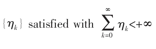
(4)The penalty function Pσ(x)is used to determine step length αk∈(0,δ]according to linear searching role to make sure that Pσ(xk+αkdk)≤minPσ(xk+αdk)+ηk.
(5)xk+1=xk+αkdk,Bkis renewed to Bk+1.
(6)k=k+1,return to step(3).
2 Containership model and computation of ultimate strength
2.1 Containership model
A 500TEU containership is used to study the nonlinear dynamic strength and its structural optimization based on hydroelasto-plasticity and ultimate strength evaluation.The prin-cipal dimensions of a 500TEU containership are summarized as blows:Ship length:119.3 m; Breadth:18.8 m;Molded depth:8.6 m;Draft:6.0 m.The hull plan of the ship is presented in Fig.2.
In this paper,a module for calculating modal shape of FEM beam is used.the wave lengths of all extreme waves would be defined as being equal to the ship length because VBM is the largest so that the condition is the most dangerous.The deformational shape of the ship beam is highly dependent on the wave length.Even if the first flexuous natural mode was assumed to be dominant when the wave length was set such that it was equal to the ship length,former ten flexuous natural modes are applied to superpose the deformational shape of ship in the extreme waves in the study.Therefore,it is sufficient to present the deformational shape of ship as the former ten flexuous natural modes.Fig.3 shows ten flexuous modal shapes of ship and their natural frequencies.

Fig.2 Body plan of 500TEU containership

Fig.3 Former ten flexuous modal shapes of ship
This computation is carried out based on an assumption that ship is under design full loading whose draft line is designed loading line.Fig.4 shows the weight distribution of 500-TEU containership.Generally,maximum weight is distributed around the middle part of ship due to the loading of cargo while less weight is appeared at two ends of ship.For the same reason,weight distribution requires the corresponding strength and rigidity distribution.In fact, no matter rigidity or the moment-curvature relation is different along ship length,maximum rigidity appears at midship.Fig.5 presents the elastic rigidity(EI)distribution of 500-TEU containership in elastic stage.

Fig.4 Ship weight distribution

Fig.5 Ship elastic rigidity distribution
2.2 Ultimate strength of 500TEU containership
For reasons of high efficiency and low computational cost,the nonlinear FEM has beenapplied to the computation of the ultimate strength of a ship’s girder.In this study,structural nonlinearity involving material nonlinearity and geometric nonlinearity was considered based on the computation of the FEM with a middle part of ship.
The nonlinear FEM software ABAQUS was used to calculate the ultimate strength of the 500TEU containership.A remeshed midship FEM model whose length was equal to 1/20 ship length was extracted from the whole-ship FEM model.To save computation time,only a half of the midship was modeled.Geometric and material nonlinearity were considered in the development of the model.The Riks-Ramm arc-length method,combined with a full Newton-Raphson iterative scheme,was used to analyze the midship FE model.The solution considers large displacements and finite strain,elastic plastic steel material capable of synthetic hardening,with a yield stress of 235 MPa,was used in the FE model.The Young’s modulus of this material was 206 GPa, and its Poisson’s ratio was 0.3.Fig.6 shows the failure mode of sagging that buckling happens in deck and upper ship structure.The ultimate bending moments are presented as follows:


Fig.6 Stress contour map of midship

Fig.7 Bending moment-curvature of 500TEU containership at midship

Fig.8 Curvature-rigidity of 500TEU containership at midship
Fig.7 illustrates the curve of curvature-bending moment of the 500TEU containership calculated using nonlinear FEM for sagging and hogging.In Fig.7,the hogging and sagging bending moment curves are shown,with curvature plotted on the horizontal axis and the bending moments plotted on the vertical axis.It is observed that the sagging ultimate moment is smaller than the hogging ultimate moment.It indicates that deck buckling is easier to appear to lead to collapse of ship structure.The sectional rigidity is calculated through the application of Eq.(11).The sectional rigidity in the elastic stage is EI=2.26e+012(Nm2),falls in the elasto-plastic stage,becomes infinitely close to zero at the point corresponding to the ultimate bendingmoment,and then becomes negative.In the case of sagging bending,when the curvature of a section exceeds 1.790e-4,that section of the ship’s beam enters the elasto-plastic stage.Fig.8 shows the rigidity-curvature curve,from which it can be determined that the rigidity remains constant while the ship is in the elastic stage but falls rapidly when the ship enters the elasto-plastic stage,ultimately falling to zero at the point corresponding to the ultimate bending moment.It is known that the load falls beyond the ultimate strength point while the sectional rigidity becomes negative.This negative rigidity cannot be iterated by the hydroelasto-plastic code,however,so it is a assumption that the ship would be disabled and collapse beyond the ultimate strength point.Therefore,the rigidity is determined as being constant zero after the ultimate strength point.The sectional rigidity EIprelated with deformational curvature is substituted into Eq.(14)to obtain the dynamic modified hydroelastic responses of ship beam.
2.3 Extreme wave models
A numerical wave tank code NWT2D(New Wave Tanker2D)performed in some previous studies is used to compose numerical extreme wave models.The program NWT2D was developed by National Maritime Research Institute in Japan.Extreme wave generation is performed by wave superposition of linear numerical regular wave and numerical focusing wave,focusing wave is generated in specific position and time,focusing wave amplitude and energy superposition is coincided with regular wave amplitude and energy to compose extreme wave which has a higher wave height.
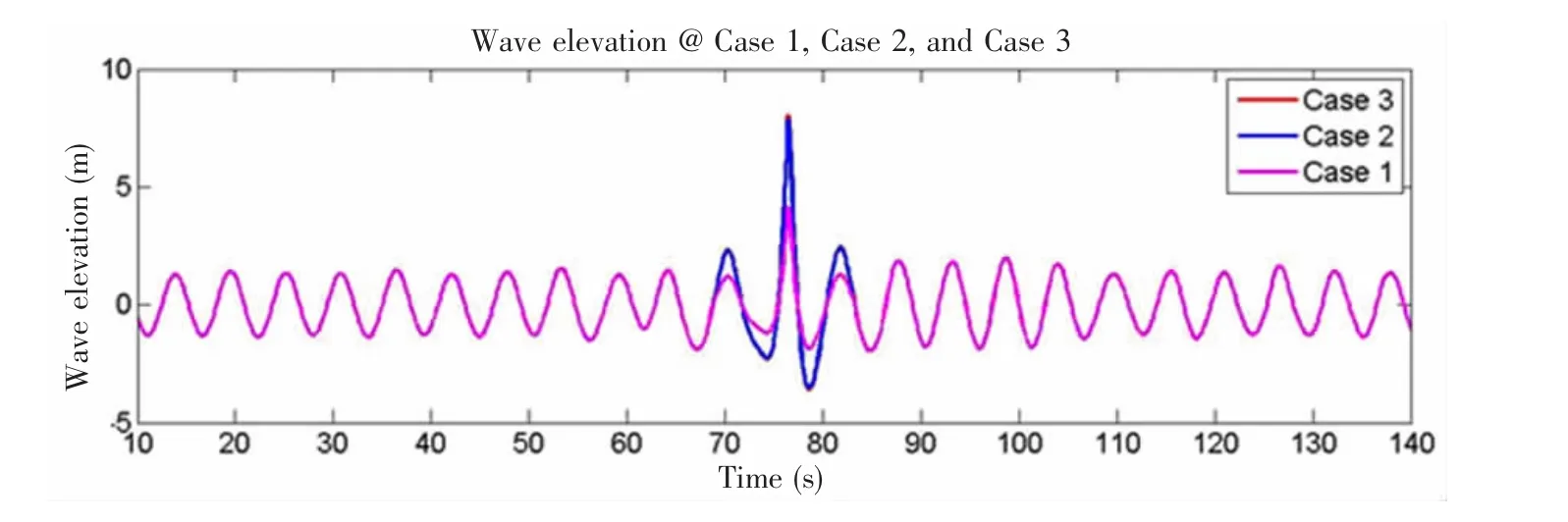
Fig.9 Wave elevation profile of containership at midship
Three extreme wave models(Case 1,Case 2 and Case 3)are presented in Tab.1 as typical extreme wave model,their regular waves are kept similarly to make sure computational comparability,regular wave height is 2.8 m while the ratio of wave length to ship lengthLw/()L is equal to 1.0.Extreme wave height is paid a close attention,three different focusing waveheights are used to change extreme wave heights such as 6.0,11.4 and 11.6.The ratios extreme wave height divided by D(molded depth)are 0.7,1.33 and 1.35,respectiuely.These three extreme wave cases are defined to indicate three typical strength condition of elastic strength, elasto-plastic strength and ultimate strength.Time-domain profiles of three extreme wave models are presented in Fig.9.
3 Calculation of hydroelasto-plasticity
3.1 Dynamic strength calculation by using modified hydroelasticity and hydroelasticity
In this study,a method for calculating the 2D modified hydroelasticity is proposed to enable the study of the dynamic response of a 500TEU containership to the extreme waves described above.A number of computations including deformational curvature and VBM were performed using the modified hydroelastic code,and they are plotted and compared with the calculations of hydroelasticity,so that the difference between the nonlinear and linear dynamic results can be obtained transparently.In addition,the course of any collapse and the reasons for the collapse are studied for extreme waves.
In this paper,a parameter of angle derived from Eq.(13)is used to manifest itself as deformation of the ship’s beam,it is solved from differential equation of global deflection wpby length.The angle at the midship section warrants close attention.The low rigidity of the beam generates a large deformational angle.Fig.10 shows the angle curves obtained with the modified hydroelasticity and hydroelasticity methods at the midship section when subjected to the three extreme waves described above.Fig.10(a)shows that there is no difference between the two methods, Fig.10(b)indicates that the modified hydroelasticity method generates a larger deformation than the hydroelasticity method, with a residual deformational ange of 0.067 degree being generated after the first large peak.Next,Fig.10(c)shows a much greater deformation,with the maximum angle obtained with the 2D modified hydroelastic method being 0.824 2 degree with a residual angle of 0.395 degree, while the maximum angle obtained with the hydroelasticity method alone has a very small value of 0.235 degree.

Fig.10 Midship curvature obtained with modified hydroelasticity and hydroelasticity
Nonlinear vertical bending moment (VBM)is obtained from the calculation of the relationship between the curvature and bending moment,as shown in Fig.7.In previous research,VBM was calculated by using linear hydroelastic code since the structural rigidity is assumed to be constant when using the hydroelasticity method.Fig.11 presents the VBM curves as obtained with the 2D modified hydroelasticity and hydroelasticity methods at midship points with the above three extreme waves.Fig.11(a)shows the VBM for the case of Case 1 at S.S.5.0. It can be seen that results obtained with the modified hdyroelastic and hydroelastic methods are in very good agreement,meaning the WH3 extreme wave generates only an elastic response from the ship.Next,Fig.11(b) shows that there is very little difference at the first large peak,but that the VBM as determined using the modified hydroealstic method is larger than that obtained with the hydroelasticity method,meaning that the extreme case of Case 2 produces an elastic-plastic response.Finally,Fig.11(c)shows a considerable difference for the first large peak,with the maximum VBM being attained at the ultimate sagging bending moment Ms.This implies that in the extreme wave case of Case 3,the response is fatal.Both Fig.11(b)and Fig.11(c)indicate that the modified hydroelastic method produces a larger VBM result than the hydroelasticity method when ship beam enters the stage of large deformation.

Fig.11 VBM as obtained with modified hydroelasticity and hydroelasticity methods at midship point
4 Structural optimization of containership in extreme wave based on hydroelasto-plasticity and ultimate strength evaluation
4.1 Overview for optimal model
The containership for optimization has the same principal dimensions as above containership.The structural optimization is performed by sequential quadratic programming method (SQP).Several basic structural sizes are determined uniformly such as the height of double bottom,the height of second deck,the space of girders,and the width of inner side structure shown in Fig.12,the height of double bottom is 1.3 m,the height of second deck arrives 6.1 m,the space of girders is 3.4 m,and the width of inner side is determined to 6.8 m.
56 design variables are determined to study the optimization problem,9 basic stiffened plate elements are included,6 design variables are involved for each stiffened plate element,each stiffened plate element is constructed by T section bar and plate,so the 6 design variables of each stiffened plate element cover stiffened space, web height,web thickness,flange width,flange thickness,and the plate thickness.Fig.12 also shows the design model and variables of 500-TEU containership at midship.Beside the basic stiffened elements,the center girder and side girder are another two design variables.
4.2 Objective function
The ship structural material is supposed to be designed least-cost as Eq.(23),the objective function is initial cost including material cost and manufacturing cost as Eq.(24),the material cost is considered based on ship weight.Material cost is determined by the 56 design variables.Main structural optimization is performed at midship section,so the initial cost CIis determined in accordance with midship section.

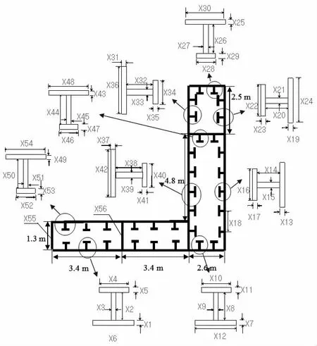
Fig.12 Optimal model and variables of 500-TEU containership
The material cost is expressed by Eq.(25),L is ship length,ρ is material density,A(x)is the area of ship section calculated by design variables.

Manufacturing cost denotes the cost due to the manufacturing cost of naval architecture. Generally,manufacture cost is determined by the number of stiffeners to some extent.The manufacturing cost is cited as Jufuku et al[11]and Sasashima et al[12],it is defined as follows:

where β is studied as manufacturing cost per stiffener by Okada et al[13],njis the number of all stiffeners,K is welding cost determined as 3%of the total manufacturing cost.
4.3 Constraint condition
Two constraint sets are defined to describe the nonlinear constraint conditions of structural optimization containership in extreme waves.One constraint set is strength constraint to make sure that optimal model satifies the strength requirement to against external extreme wave load while the extreme wave height is given.Strength constraint which makes sure that nonlinear dynamic maximum bending moment calculated by hydroelasto-plastic code should be smaller than ultimate bending moment calculated by Smith code.Another constraint set is tomake sure that the size of optimal structural members should satisfy the structural size requirement of Common Structural Rules(CSR)specified by International Association of Classification Societies.Strength constraint is explained as follows.

where Mmax-psand Mmax-phare the maximum nonlinear dynamic sagging and hogging bending moments solved by using above hydroelasto-plastic code as Fig.11 shows.Mu-sand Mu-hare the ultimate sagging and hogging bending moments solved by a Smith method code.
Another set of constraints should be satisfied for the requirement of CSR specified by International Association of Classification Societies as follows:

4.4 Optimal results
Once an allowed extreme wave height ratio Hf/D is given,the maximum dynamic bending moment at midship should be smaller than the ultimate bending moment.The extreme wave height ratios are defined from 0.6 to 1.6 with a interval of 0.1,9 optimization computations based on hydroelasto-plastic strength constraint are performed.
All design variables are analyzed to observe their changing tendency if allowed wave height ratio is changed from 0.6 to 1.6 and Froude number of extreme wave is fixed at Fr=0.3. Fig.13 is optimal plate thickness as extreme wave height ratio changes.In Fig.13,It is seen obviously that the design variable x(25)representing main deck plate thickness obtains sharper increasing sensibility,the design variable x(13)denoting down side plate thickness,the design variable x(19)denoting upper side plate thickness,the design variable x(31)denoting upper inner side plate thickness,and the design variable x(43)denoting the second deck plate thickness get a medium increasing tendency,but the design variable x(1)and x(49)denoting the outer and inner bottom plate thickness just almost has no changes.It implies that the plate thickness at bottom structures is not sensitive to promote ultimate strength,it is analyzed that the bottom structures are too close to the position of neutral axis of ship section.

Fig.13 Optimal plate thickness as extreme wave height changes
Fig.14 is the optimal web height by chang-ing extreme wave height ratio.It manifests that each optimal web height increases a lots if extreme wave ratio is from 0.8 to 1.0,but the increasing amplitude is relatively small after Hf/D= 1.0,the maximum web heights tend to be around 200 mm.Subject to local buckling,it is impossible to promote strength by increasing web height infinitely,the ultimate strength is not sensitive when web height arrives a certain value.Fig.15 is the optimal web thickness.It is observed from Fig.14 that the design variable x(21)denoting web thickness of upper side stiffener and the design variable x(27)denoting web thickness of deck stiffener have sharper increasing,while other variables have medium increasing tendency.It means that the web thickness of upper side stiffener and deck stiffener is sensitive to promote ultimate strength.
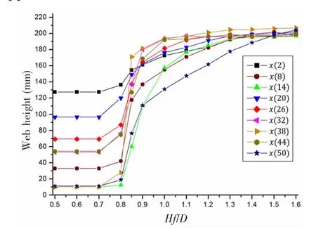
Fig.14 Optimal web height as extreme wave height ratio changes

Fig.15 Optimal web thickness as extreme wave height ratio changes
Fig.16 shows the optimal flange widths.It is observed obviously that the variable of x(16), x(22),x(34)and x(40)representing the flange widths for four side structures obtain significant increasing after Hf/D=0.7,while the flange width of other stiffeners do not have obvious changing.It implies that the flange width at side structures is sensitive to promote ship ultimate strength while other flange width is not sensitive for structural optimization.Fig.17 is the optimal flange thickness as extreme wave height ratio changes.It is observed from Fig.17 that the most of design variables denoting flange thickness have increased but the increasing amplitudes are rather small.It implies that the flange thickness is not sensitive to promote ultimate strength.

Fig.16 Optimal flange width as extreme wave height ratio changes

Fig.17 Optimal flange thickness as extreme wave height ratio changes
5 Conclusions
This paper used a 2D hydroelasto-plasticity method which can consider the coupling of structural nonlinearity and extreme waves to calculate the nonlinear dynamic strength and large deformation of containership in extreme waves by changing their maximum wave height and wave speed.And then nonlinear structural optimization of the containership is performed based on hydroelasto-plasticity and ultimate strength evaluation.Several conclusions are obtained in accordance with above computational results:
(1)Extreme wave height is significant to containership strength.The hydroelasto-plasticity method considers a smaller extreme wave height such that the value of the ultimate bending moment is attained more quickly than that by the hydroelasticity method,given that the large deformation is taken into account.
(2)The encountered wave speed does not have a negligible effect on a ship’s strength. For a given wave height,the hydroelasto-plasticity method arrives at the ultimate bending moment at a lower wave speed than that by the hydroelasticity method.
(3)Plate thickness of ship hull is sensitive to enhance the ultimate strength of ship.
(4)The web height at deck structure and the flange width at side structures are effective means to promote ship’s ultimate strength.But it is not sensitive when web height arrives a certain value which is determined by stiffener local buckling based on ultimate strength evaluation.
In the future,we will take the 3D effect of hydroelasto-plasticity into account,with every structural member of the ship being included in the computations.Similar optimization method which is combined ultimate strength evaluation with the structural requirement of Common Structural Roles(CSR)is able to be performed for other ship types such as oil tanker and bulk carrier.
[1]Peliniovsky E,Kharif C.Physical mechanisms of the rogue wave phenomenon[J].European Journal of Mech.B/Fluids, 2003,22:603-634.
[2]Muller P,Garrett C,Osborne E.Rogue wave[J].Oceangraphy Society,2005,18:66-75.
[3]Yang guansheng,Dong yanqiu,Chen xuechuang.Freak wave[J].Oceaning Engineering,2002,4:105-108.
[4]Yamamoto,Yoshiyuki,Fujino,Masataka,Fukaswa,Toichi.Motion and longitudinal strength of a ship in head sea and the effects of non-linearities[C].Conference of the Society of Naval Architects of Japan,1978.
[6]Huang L L,Riggs H R.The hydrostatic stiffness of flexible floating structures for linear hydroelasticity[J].Marine Structures,2000,13:91-106.
[7]Iijima K,Kimura K,Xu W,Fujikubo M.Hydroelasto-plasticity approach to predicting the post-ultimate strength behavior of ship’s hull girder in waves[J].Journal of Marine Science and Technology,2011,16(4):379-389.
[8]Liu W,Suzuki K,Shibanuma K.Nonlinear dynamic response and structural evaluation of container ship in large extreme waves[J].Journal of Offshore Mechanics and Arctic Engineering,2015:64-73.
[9]Liu W,Suzuki K,Shibanuma K.Nonlinear dynamic response and strength evaluation of a containership beam in extreme waves based on hydroelasticity-plasticity method[C].Conference Proceedings of the International Society of Offshore and Polar Engineers,2014,4:652-657.
[10]Liu W,Suzuki K,Shibanuma K.A two-dimensional hydroelastoplasticity method of a container ship in extreme waves[J]. Journal of Offshore Mechanics and Arctic Engineering,2015:84-93.
[11]Jufuku H.Ship structural optimization considering cost of life cycle[M].Tokyo:The University of Tokyo,2012.
[12]Okada T.Optimization method in ship structural design and CAD[M].Tokyo:The University of Tokyo,2006.
基于一个二维水弹塑性方法和极限强度评估的集装箱船结构优化研究
刘维勤1,宋学敏1,吴卫国1,铃木克幸2
(1.武汉理工大学交通学院,武汉430063;2.东京大学工学系研究科系统创成专攻,日本东京113-8656)
海上极端波过去常常导致船舶结构的极限破坏,而船舶的极限崩溃涉及到船体结构的动态极限强度和结构非线性。该文通过二维的水弹塑性方法研究了集装箱船在极端波中的非线性动态强度,该方法考虑了船体的极限强度以及船体结构的非线性和波浪之间的耦合。并通过该二维水弹塑性方法和极限评估方法研究了船体结构的结构优化。文中还通过二次规划法(SQP)来优化基于非线性的动态强度的集装箱船体结构。最少的结构成本是本优化的目标函数,约束条件保证船体的强度要小于结构的极限强度,并且结构设计尺寸要满足规范的要求。随着设计波高的变化,这些优化的设计变量的变化趋势得以发现,一些研究的结论可用于船舶规范的参考。
非线性动态强度;极限强度;水弹性;水弹塑性;结构优化;二次规划法;集装箱船;极端波
TV131.2
:A
刘维勤(1985-),男,武汉理工大学交通学院讲师;
TV131.2
:A
10.3969/j.issn.1007-7294.2017.06.007
1007-7294(2017)06-0722-17
宋学敏(1986-),男,武汉理工大学交通学院讲师;
date:2016-11-17
Study of Hydroelasto-plasticity Method of Ship Structure(51509197)
Biography:LIU Wei-qin(1985-),male,lecturer,E-mail:liuweiqin_123@sina.com;
SONG Xue-min(1986-),female,lecturer.
吴卫国(1960-),男,武汉理工大学交通学院教授;
铃木克幸(1964-),男,日本东京大学工学系研究科教授。
猜你喜欢
杂志排行

船舶力学的其它文章
- Simulation of Irregular Wave Impact on Horizontal Plate Structures
- An Adaptive Unscented Kalman Filter for Tracking Sudden Environmental Forces Changes in Dynamic Positioning System
- Experiment Research of Axial Dynamic Vibration Absorbers Based on Magneto-Rheological Elastomers Using for Ship Shafting
- Acoustic Characteristics of Underwater Explosion about Metal Grid of Detonating Cords
- Numerical Simulation of Nonlinear Sloshing Waves in Three-dimensional Tank based on DBIEM
- New Impulsive Factor in Representing Cabin Damage under External Air Explosion