Electronic power transformer for smart grids: Improving the controllability of electric power systems
2017-06-06WANGDanTIANJieMAOChengxiongLUJiming
WANG Dan, TIAN Jie, MAO Cheng-xiong, LU Ji-ming
(School of Electrical and Electronic Engineering, Huazhong University of Science and Technology, Wuhan 430074, China)
Electronic power transformer for smart grids: Improving the controllability of electric power systems
WANG Dan, TIAN Jie, MAO Cheng-xiong, LU Ji-ming
(School of Electrical and Electronic Engineering, Huazhong University of Science and Technology, Wuhan 430074, China)
Today’s electric power systems (EPSs) are facing new challenges including the increasing penetration of renewable generation, increasing participation of demand response from consumers, and rapid growth of non-linear and sensitive loads. The smart grid is expected as an effective approach to solving these problems. However, how controllable the grid is, how possibly smart the grid is. Making the EPS more controllable is the road to make it smarter. In this paper, electronic power transformer (EPT) is proposed to improve the controllability of the EPS. The application scenarios of the EPT are analyzed in detail. Three case studies including applying EPTs to the generation system, transmission system, and distribution system are analyzed. The simulation results demonstrate there are enormous potential of the EPT to enhance the controllability of the power systems.
electric power system (EPS); electronic power transformer (EPT); controllability; smart grid; solid state transformer (SST); power electronic transformer (PET)
1 Introduction
Improving the controllability of the electric power system (EPS) is a key point for the modern electric power supply. Unfortunately, the dynamics of generation, distribution and consumption are fully coupled in the traditional EPS[1], which makes the EPS cumbersome. Before 1990s, the generator was the sole unit for regulating real and reactive power simultaneously, thereby not being regulated fast. Thus, the EPS had poor controllability. With flexible AC transmission system (FACTS) technology development, the EPS controllability has been enhanced[2]. For example, the network reactive power can be adjusted by static var compensators (SVCs) or static compensators (STATCOMs), which can increase the power transfer capability of the power systems.
To achieve carbon reduction, nowadays, the smart grid is being introduced for the purpose of facilitating effective integration of renewable energy and demand response into the system[3]and enhancing the safety of the electricity transmission[4]. The smart grid is a clean, safe, secure, reliable, resilient, efficient, sustainable and strong electric system. It will have the following characteristics[5]: ① Self-healing: reconfiguration of the system to reroute supplies of energy to sustain power to customers; ② Flexible: rapid and safe interconnections of distributed generations (DGs) and energy storages; ③Interactive: allowing all key participants (operators and customers) in the energy system to play an active role in optimal management of contingencies; ④Optimized: knowing the status of every major component in real or near real time, having control equipment to provide optional routing paths and providing the capability for autonomous optimization of the flow of electricity throughout the system; and so on.
It is required for the smart grid to have strong and flexible control technologies including equipment and methods to achieve self-healing capability, improved efficiency and interactive load and source management for better performances. Up to now, the traditional EPS is awkward and non cost effective. From the view of the smart grid, improving the controllability of the EPS is still a challenge, especially under the condition of integrating renewable generations (RGs), including large-scale centralized and small-scale distributed generations, and energy storage systems (ESSs).
The big problem of RGs is that the production is variable, which is often referred to as intermittency. Therefore, the power provided by the RGs is a stochastic power flow. The high penetration of RGs causes significant challenges for the EPS operating, generation planning and coordination of supply with demand in real time[3,6]. The flexible and fast control measures are required to minimize these negative impacts. At critical points of generation, transmission and distribution, new intelligent and controllable devices are needed to improve the active control capability of the EPS.
The power transformer is a major component in the EPS. The transmission and distribution systems are heavily dependent on transformers. The conventional power transformer does not have any active control ability, which cannot satisfy the requirement of the smart grid. Additionally, it is one of the bulkiest components due to the low operation frequency.
Electronic power transformer (EPT), also known as power electronic transformer (PET), and solid state transformer (SST)[7,8], is a static device that transfers electrical energy from one circuit to another through electromagnetic induction-based transformation and power electronic conversion technologies[9]. It has the ability of changing the voltage level, current, phase angle, frequency, phase sequence, waveform, or/and other electric characteristics of the electricity. Generally, an EPT has two basic elements: one is the power electronic converter, and the other is the medium-or high-frequency (MF or HF) transformer, as shown in Fig.1[10]. Basically, the power electronic converters are the interfaces connecting with external primary and secondary systems, and the high-frequency transformer is to couple the converters and provide galvanic isolation between the primary and secondary sides.

Fig.1 Concept diagram of EPT
The EPT can not only achieve the functions of the conventional line frequency transformer, but also realize the functions of the operation control equipment (such as FACTS and DFACTS devices) with involving the high frequency isolation and the power electronic conversion technologies[11,12]. Moreover, the EPT can offer more advantages compared to the conventional transformer plus FACTS/DFACTS devices such as higher power density, higher efficiency, more stable output, and more flexible regulation ability. It will provide a competitive approach for the EPS to achieving better operating performances and greatly enhance the controllability of the EPS. Some researchers have discussed the related topics of applying EPTs to smart grids[13-17]. The major aim of this paper is to comprehensively present how the EPT is applied to enhance the controllability of the EPS.
2 Categories of EPT and application scenario
2.1 Categories
Unlike the conventional transformer, the EPT can be used not only to transform AC electricity, but also to transform DC electricity, or to couple AC and DC electricity. The capability of handling both AC and DC power makes the EPT have the potential to solve the problems faced by new type power grids, such as microgrids, DC grids, and hybrid AC/DC grids. Herein, EPTs are divided into three categories to explain the functions of the EPT for different electricity.
(1) AC-EPT
The AC electronic power transformer (AC-EPT) is used to transfer electric power from an AC system to another AC system, as shown in Fig.2 (a). The two AC systems may have one or more of following characteristics: different voltage levels, different frequencies, different phase quantities, different phase angles, different phase sequences, different waveforms, etc.

Fig.2 Three categories of EPTs
The AC-EPT can be used to replace the conventional line frequency power transformer in the traditional EPS. It also can be used to connect the AC output DGs (e.g., wind power, small hydro power, and micro-turbine) with the AC distribution system or AC loads.
(2) DC-EPT
The DC electronic power transformer (DC-EPT) is used to transfer electric power from one DC system to another DC system, as shown in Fig.2 (b). The two DC systems may have different voltage levels. The DC-EPT can be used to connect the DC output DGs (e.g., PV, fuel cell, battery and so on) with the DC distribution system or DC loads.
(3) Hybrid-EPT
The AC-DC or DC-AC electronic power transformer (called Hybrid-EPT) is used to transfer electric power between an AC system and a DC system, as shown in Fig.2 (c). The Hybrid-EPT can be used to connect AC sources with the DC distribution system or DC loads, or connect DC sources with the AC distribution system or AC loads.
In Fig.2, the AC-HFAC (HFAC-AC) and DC-HFAC (HFAC-DC) converters may be single-stage direct converters or multi-stage converters, as required. Since DC is regarded as a special case of AC, the DC-EPT and Hybrid-EPT can also be considered as the special cases of the AC-EPT. So, for simplicity, only the AC-EPT will be discussed unless specified otherwise.
Although so many topologies have been developed for the AC-EPT[18-25], the topologies with DC-link units on the primary or secondary sides, or on both sides, as shown in Fig.3, which depends on the real application, are competitive. It can provide more unrestricted and flexible regulation ability. Fig.4 shows a detailed architecture of the AC-EPT with DC-link units for high voltage and high power applications.

Fig.3 AC-EPT with DC-link
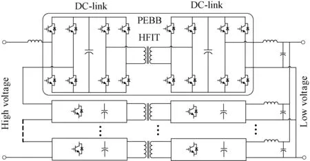
Fig.4 Typical architectures of AC-EPT
2.2 Application scenarios
The modern EPS includes generation, transmission and distribution subsystems. From the point of view of system-level function, the application scenarios of the EPT can be classified as follows.
Scenario I: EPT is applied in the generation system where the EPT is used to step the voltage up or down and transfer power from the generation unit to the EPS or loads. In this case, the main aim of the EPT is to collaborate with the generator to produce maximum power or satisfy the demand of loads with high efficiency and good dynamic characteristics.
Scenario II: EPT is applied in the transmission system where EPTs are used to integrate the various generation subsystems and transmission lines together to form electric power transmission grids. In this case, the function of the EPT is to provide the ability of flexible power flow control to enhance the stability, improve dynamic performances, and increase operation efficiency.
Scenario III: EPT is applied in the distribution system where the EPT is used to power loads. In this case, the aim of the EPT is to guarantee the power quality of the power supply and reduce the network power losses.
The above means of classification are very useful for understanding the functions of EPTs in the EPS. However, for the convenience of the detailed control design, another classification of the application scenario is more reasonable. Wherever the EPT is equipped, the case is categorized into one of the three types as follows.
(1) EPT applied between electric source and loads
The first case is that the EPT is used to connect an electric source with passive loads and transfer electric power from the source to loads, as shown in Fig.5 (a). The electric source may be EPS, synchronous generator or other independent power source (e.g., DG and battery). In this application case, the EPT has the following operation and control characteristics.
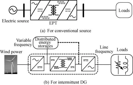
Fig.5 EPT between electric source and loads
1) The EPT should track the frequency of the electric source. Furthermore, the constant DC-link voltage control should be adopted by the primary side of the EPT. The reactive power exchanging between the source and EPT can be flexibly controlled.
2) In the secondary side, the output voltage control is required for the EPT to supply constant voltage and constant frequency electric power to the loads. The EPT is also able to provide variable voltage and/or variable frequency supply if required. Unlike the traditional power transformer, the EPT can guarantee the regular and urgent performance of the secondary voltage.
3) The quantity of real power transmitted through the EPT depends on the loads if the electric source is enough.
In addition, when the source is an intermittent DG (e.g., wind power), as shown in Fig.5(b), it is very easy for the EPT to integrate the energy storage unit which performs the function of offsetting the intermittency of the source to obtain smooth power supply.
(2) EPT applied between generation and infinite-bus
The second case is that the EPT is used to connect the generation unit to the EPS the capacity of which is much larger than the generations (termed infinite-bus), as shown in Fig.6. The generation unit may be centralized power plant or DG. The function of the EPT is to transfer electric power from the generation to the system. It has the following characteristics.
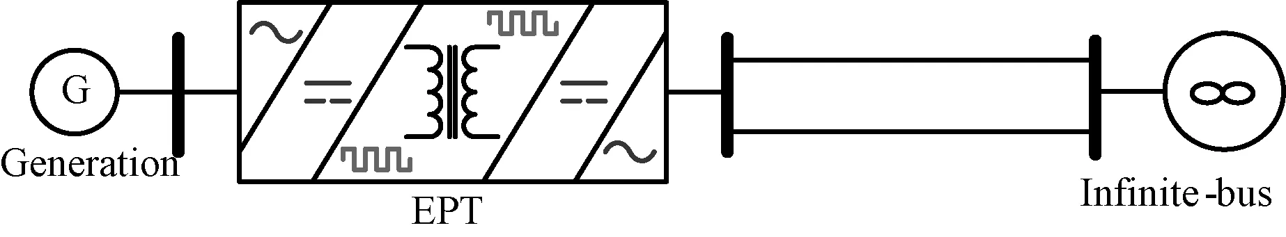
Fig.6 EPT between generation and infinite-bus
1) In the generation-side, the constant real power control mode is applied for the EPT to control the penetrating power, which can be realized by controlling the terminal of the EPT as a virtual infinite-bus. Since the EPT cannot generate real power, the power regulation unit of the generation must cooperate. The reactive power exchanging between the generation and EPT can be flexibly controlled. The generation can be operated in the zero-reactive power mode to produce more real power.
2) In the infinite-bus-side, the EPT must track the frequency of the EPS and the constant DC-link voltage control is required. Like the generation-side, the reactive power exchanging between the EPT and the system can also be flexibly controlled.
3) The EPT should perform the maximum power point tracking (MPPT) control if the generation is PV, or wind power, etc. Moreover, the EPT will allow the DG operating under optimal condition. For example, the wind generation operates in a wide range variable speed mode, which favors to capture more energy from wind.
4) An additional function of the EPT is to improve the system damping in transient state through the additional damping controller.
(3) EPT applied between two electric power grids
If two electric power grids are interconnected by a conventional transformer, they must have the same frequency and operate synchronously. If the interconnection is realized using an EPT, as shown in Fig.7, however, the synchronous operation will not be required for the two grids. In this case:
1) The two converters on the two sides of the EPT track the frequencies of the corresponding grids, respectively.
2) The one side realizes the constant DC-link voltage control and the other side adopts the constant real power control.
3) The exchanging reactive power either in primary side or in the secondary side can be adjusted independently to meet the demand.

Fig.7 EPT between two electric power grids
It is worth to notice that the EPT has the ability to maintain the voltage at the bus it connected to, which is very important for the power system of today. The EPT may help restore the bus voltages immediately when a fault takes place, which is worthwhile for improving the system stability. Furthermore, the EPT can even shut down the transmitted active power to obtain stronger voltage support ability in an emergency.
3 EPT in generation system
The generation subsystem including centralized and distributed power generations is the energy source of the EPS. In the smart grid, it should be able to supply sufficient power at minimum cost under regular operation conditions, and to provide suitable power to support the EPS against breakdown in emergency. However, it is very difficult to meet the requirements only depending on the regulating system of the generation unit. External control devices and methods are required. Using the EPT as the generation transformer is an approach.
In the generation system, the role of the EPT is to help the generation unit to be able to meet the continually changing load demand for real and reactive power at minimum cost and with minimum impact. For the traditional synchronous generator, the EPT can minimize the reactive power output of the generator and help to maintain the rotor speed under disturbances.
Almost all renewable energies are erratic. They are variable diurnally, seasonally or yearly. In order to use them as great as possible, the technology of MPPT is proposed. If the EPT is used as the interface between RGs and the utility grid or loads, it will allow the RGs operating under optimal conditions.
Since most of the distributed sources do not provide the electric power at line frequency and voltage, the structure of the DG system, the rating of voltage, and the frequency vary from region to region[26]. Only using the line frequency power transformer is no longer fit for this situation. As a consequence, lots of power electronic converters have been introduced[27]. The EPT provides a novel competitive approach for the DG interconnection.
The EPT can be used to interconnect various generations with different frequencies and voltage levels and/or feed them to the existing AC grids or loads. If required, the EPT can also directly power DC loads which are becoming more commonplace because they result in more efficient use of electrical energy[28].
4 EPT in transmission system
The complexity of the transmission system is continually increasing because of the growth in interconnections and use of new technologies, and financial and regulatory constraints have forced utilities to operate the systems nearly at stability limits[29]. This has made it is more and more difficult to maintain power system stable and efficient operation. Improving the controllability of the transmission system is the fundamental way to resolve this problem.
On the other hand, during the last few years, the interest in controlling power flows in transmission systems has increased significantly. The reasons boil down to: system instability, power flow loops, high transmission losses, voltage limit violations and inability to utilize transmission line capability up to the thermal limit[30].
Although the unified power flow controller (UPFC) and high voltage DC transmission (HVDC) can provide the capability of controlling power flow, the line frequency transformers are required which makes the system bulky and reduce the control flexibility.
4.1 EPT for damping of the system oscillation
Rotor angle stability is essential to the performance of the transmission system. It involves the ability of the system to remain in synchronism under normal operating conditions and after experiencing a disturbance because power systems mainly rely on synchronous machines for generation of electrical power. There are two kinds of instability modes: aperiodic or non-oscillatory instability and oscillatory instability. The latter, due to lack of sufficient damping torque, is serious under small disturbances in today’s practical power systems[31]. Determining how to damp the electromechanical oscillations is the principal problem.
It has been proven that the EPT is beneficial to improving the damping ability of the SMIB system[32,33]. To observe the effects of the EPT, two-equivalent-machine simplified system is proposed, as shown in Fig.8[34]. In this model, SMIB 1 denotes one part of the power system, and SMIB 2 denotes the rest of the power system. Based on the equivalent system, not only the oscillation between the two parts of the transmission system can be analyzed, but also the influence of the local generator group can be considered. The system can be simplified as two synchronous machines with the classical model.

Fig.8 Two-equivalent-machine simplified power system with EPT
In Fig.8,PandQare the output real power and reactive power of the generator.Ut,UandUsare the voltages of generator, transformer and infinite bus system, respectively.xd,xt, andxsare the equivalent inductances of generator, conventional transformer and transmission line.UE1andUE2are the AC voltages of EPT.xE1andxE2are the filter inductances of EPT. And subscript 1 and 2 denote SMIB 1 and SMIB 2, respectively.
If the EPT is considered with the simplified dynamic model[34], the dynamic models of the system are
Whereδandωare the rotor angle and angular velocity, respectively.Pm,DandHare the input mechanical power, damping constant and inertia constant of generator.CdcandUdcare the equivalent DC-link capacitance and voltage of EPT.id1andid2are the DC-link currents of EPT, respectively.
By linearising (1), we can obtain the state variable equations of the power system installed with the EPT
(2)
wheremandθare the modulation index and phase angle of the control signal of EPT, respectively.k11andk21are synchronizing torque coefficients.k13andk23are changes in electrical torque for a small change in DC voltage.k17andk27are changes in current for small change in rotor angle.k9is the impedance factor.kCE1andkCE2are changes in current for a small change in the modulation index.kCθE1andkCθE2are changes in current for a small change in the phase angle.kpE1andkpE2are changes in electrical torque for a small change in the modulation index.kpθE1andkpθE2are changes in electrical torque for a small change in the phase angle.
From (2), the small-signal model (named Heffron-Phillips model) of the system with EPT is shown in Fig.9. The figure shows that there are four choices of input control signals of the EPT to superimpose on the damping function of the EPT,mE1,mE2,θE1andθE2. And the EPT provides damping torques directly through coefficientskpEx,kpθEx, andkx3(x=1 or 2) into the electromechanical oscillation loop.

Fig.9 Small-signal model of two-equivalent machine power system with EPT
As shown, the damping function of the EPT is achieved through two channels. The first one (damping channel 1) is that the input control signals (mE1,mE2,θE1andθE2), which means terminal voltages regulating by the EPT, directly apply into the electromechanical oscillation loop by coefficientskpEx,kpθEx(x=1 or 2). The other one (damping channel 2) is that the DC-link voltage, which denotes energy buffering by the capacitors in the EPT, applies into the electromechanical oscillation loop by coefficientskx3(x=1 or 2).
To demonstrate the conclusion of the damping effect of the EPT, non-linear numerical simulations are carried out. The detailed simulation parameters are presented in [34]. The oscillations are triggered by the three-phase to ground fault. The simulation results are presented in Fig.10.

Fig.10 Simulation of two-equivalent-machine power system with EPT on three-phase to ground fault in 1# system
As shown in Fig.10, when the three-phase to ground fault occurs at the point shown in Fig.8, the power angle oscillation arise in 1# system and the system cannot keep stable if the system without EPT-based damping controller. While the power angle oscillation is small and the system can keep stable if the system is equipped with EPT-based damping controller. It indicates that the EPT can provide effective damping to maintain the power system stable. The major reason for such performance is that the EPT improves the controllability of the system: it can regulate both the magnitudes and phase angles of the AC voltages in the primary and secondary sides rapidly to satisfy the requirements of the system (damping channel 1), and can generate or absorb power by the DC link energy store unit to alleviate the transient power imbalance in the system (damping channel 2). In general, it achieves such performances because the EPT provides an adequate damping control via swift real and/or reactive power flow regulation.
4.2 EPT for economic dispatch (ED)
Although the transmission system is designed to guarantee that the power system operation is reliable and economic, the events of one or more transmission lines becoming overloaded and the stability margin for a transmission link becoming too small are still popular, because the network of today is so complicated. The situation where a low impedance line carries much more power than originally designed for, will cause that the whole network is underutilized if load flows were distributed naturally. Furthermore, if the overload is not alleviated in time, the process of power system cascading may start, leading to power system separation. Therefore, a flexible and smart power flow control or optimization is necessary for the looped transmission system. The economic dispatch is a typical case of the power flow control.
Considering the power system installed with an EPT shown in Fig.11, the EPT is used to control the power flow from A-Bus to B-Bus. Based on the requirements of the system, the EPT can maintain the bus voltages at the specific values because the exchanging reactive power either in the primary side or in the secondary side can be controlled independently. So, both A-Bus and B-Bus can be treated as load buses or voltage controlled buses. In this case, A-Bus is a load bus and B-Bus is a voltage controlled bus. According to the relations between state variables ofP1,P2,Q1,UB,Udcand control variables ofδE1,δE2,mE1,mE1, the EPT control variables for the given power flow condition can be calculated by performing a power flow analysis with the EPT modeled.
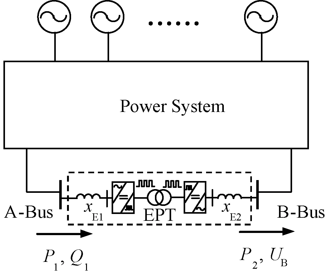
Fig.11 EPT installed in transmission system for power flow control
The objective of the ED is to optimize the power flow by EPTs so that realize the minimization of the power loss and the qualified voltage quality under the condition of the secure operation. The objective function of the ED can be represented as following:
Whereλisthepenaltyfactor.And

ΔUim=Uimax-Uimin
Theconstraintconditionsincludeequationandinequalitypartsofwhichtheequationconstrainisthepowerequilibriumconstraintofloadnodes.Theinequalityconstraintconditionsincludestatevariablesandcontrolones,whichmeansallthestateandcontrolvariablesmustbewithinspecifiedpracticallimits.FortheinstalledEPTs,theinequalityconstraintconditionsofthecontrolvariablesaredescribedbelow:
(4)
Fig.12showsthesingle-linediagramoftheIEEE30-bustestsystem.Thetransformers,excepttheonebetweenBuses27and28,arereplacedbytheEPTs.
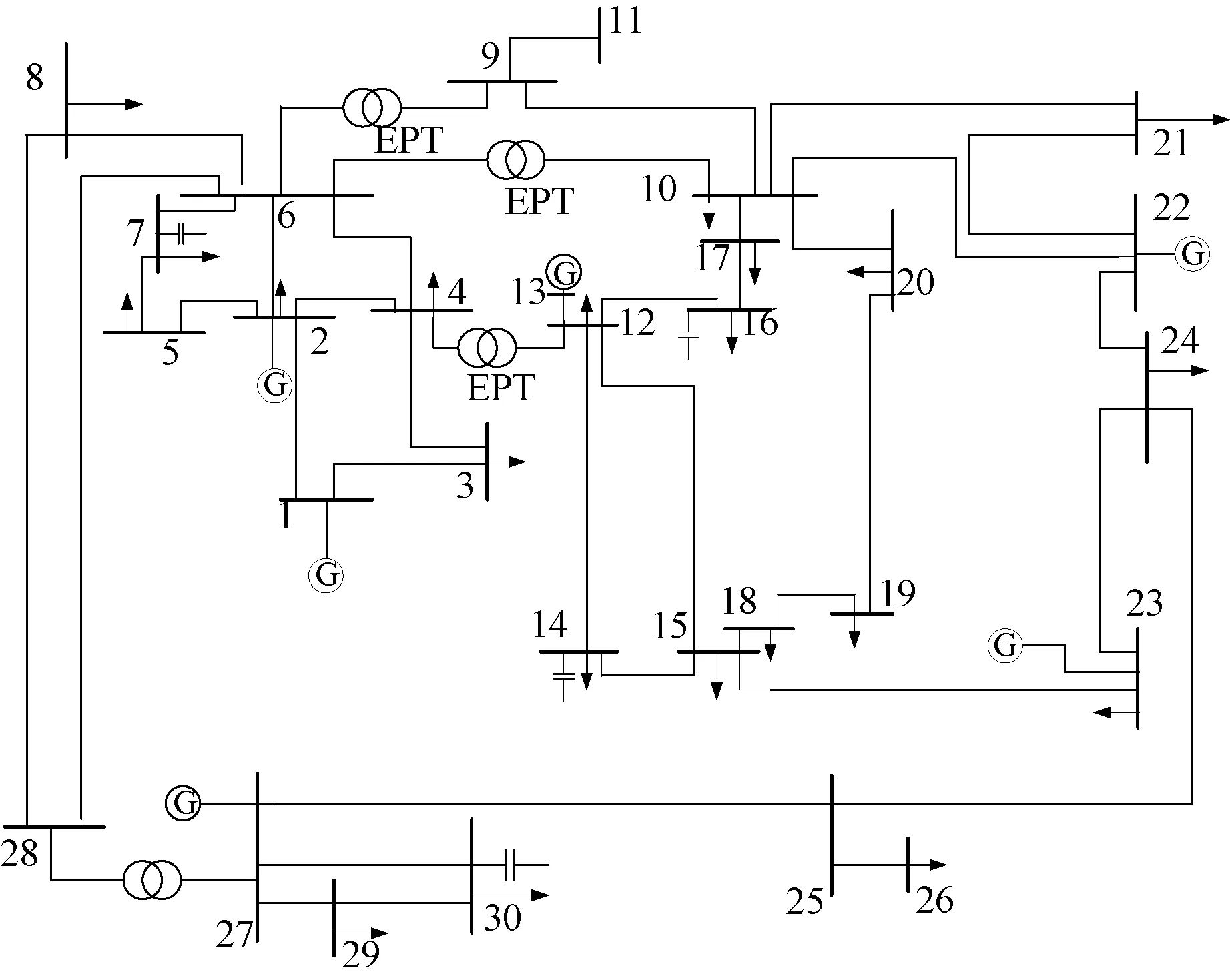
Fig.12 IEEE 30-bus system (Transformer between buses 27 and 28 is reserved and other three transformers are changed into EPTs)
Fig.13andTab.1providesomesimulationresults.Asshown,theEPTsprovidebettervoltageperformancesandmakelesspowerlosses.ThemajorreasonisthatthepowerflowcontrolinthesteadystatebecomeseasilysinceEPTsareappliedinthetransmissionsystem.

Fig.13 Voltage profiles
Additionally,becausetheEPTiscapableofrealizingflexiblefrequencyvariation,itispossibleforthepowersystemworksunderthevariablefrequencycondition.Comparedwithtraditionalfixedfrequencytransmissionsystems,thevariablefrequencytransmissionsystemhasseveraladvantages[35]: ①Enhancingtherotoranglestability; ②Makingpowerflowcontrolflexible; ③Improvingtransmissionlineefficiency; ④Increasingutilizationfactorofatransmissionline.

Tab.1 Power loss and reactive compensation
5 EPT in distribution system
The power quality of the voltage and the distribution efficiency are mainly concerned by the distribution system operator because the requirements for continuous delivery of the “clean” electric energy and the efficient and comfortable use of all electrical equipment were, and still are, primary objectives of all EPSs[30]. Furthermore, more and more modern loads, which are much more sensitive to various power quality disturbances than their predecessors, are becoming popular.
5.1 Power quality control
Fig.14 (a) shows the feeder powered by a conventional transformer with a unified power quality conditioner (UPQC). In order to achieve both harmonic voltage compensation and harmonic current compensation, the UPQC consists of combined series and shunt transformers and two converters. Using an EPT is a competitive choice as shown in Fig.14 (b), compared with equipping a UPQC.
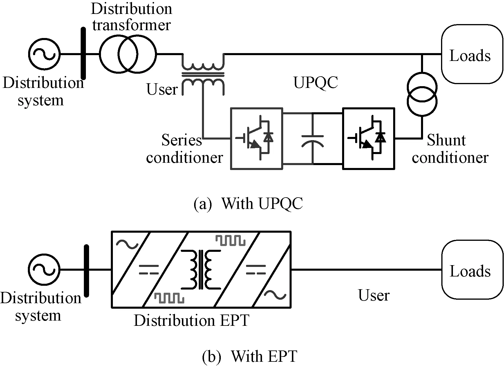
Fig.14 Power quality control in distribution system
Some simulations are carried out based on Fig.14 (b) with the capacity of 1600kV·A and the voltage of 10kV/400V. Three typical power quality disturbances, viz: voltage sag and swell and voltage flicker, are simulated. The results are shown in Fig.15 and Fig.16[10]. They indicate that the EPT enables mitigating the power quality issues when it replaced the conventional power transformer to power a feeder. This effect is from the high-level controllability of the EPT.

Fig.15 Waveforms under voltage sag and swell

Fig.16 Waveforms under voltage flicker
5.2 Voltage support
Reasonable reactive power distribution would result in not only strong voltage support but also low network losses and high efficiency. This section would focus on how to realize reactive power control by EPTs in the distribution system.
A typical distribution system is composed of one or more distribution substations consisting of one or more feeders. With a rare exception, the feeders are radial or are radially operated, which means that there is only one path for electric energy to flow from the source to the customer. To regulate the bus voltages and reactive power flow, on-load tap changing (OLTC) transformers and switched capacitors are equipped in the system. However, the drawbacks of the OLTC are obvious: step regulation, limited operation times per day, and the risk of voltage collapse, etc. Certainly, this results in a great challenge to the smart grid.
The EPT provides a good approach. It has following merits at least when OLTC transformers are replaced by EPTs: ①Providing smooth voltage regulation without operation time limitation; ②Performing fast reactive power compensation and fast voltage support; ③Enhancing voltage stability.
Tab.2 shows some simulation results to confirm the EPT performances in the reactive power flow optimization and voltage control for a 42-node system with EPTs or 19 OLTC and 8 compensation nodes.

Tab.2 Node voltage distribution statistics with load changing
The simulation results in Tab.2 confirm that the bus voltages remain invariable in amplitude regardless of load changing which thanks to that the EPTs can serve as reactive power sources to provide reactive power quickly. That is, the EPT can provide voltage support for the receiving ends. In weak systems, the voltage collapse occurs if the transmitted electric power exceeds beyond a certain value. However, if EPTs equipped, they can prevent the voltage collapse by keeping the voltage constant at the receiving end. At the same time, the network power losses are reduced effectively and the investment cost of reactive compensation equipment is saved greatly when the EPTs are applied.
5.3 New distribution networks
The future renewable electric energy delivery and management (FREEDM) system was proposed in [36]. It is a novel efficient grid integrating highly distributed and scalable alternative generating sources and storage with existing power systems. The EPT is one of the key elements in the FREEDM system.
The EPT is also making it possible to apply the DC distribution technology[37]. The DC distribution system enables great improvement of the penetration of DGs[38]. Fig.17 shows how to use EPTs to construct a DC distribution system with interconnecting various DGs and RGs.

Fig.17 Multi-level DC distribution network
5.4 Industrial prototype development
Now, the most important thing is to realize the application of the EPT in the real power system. We have built a three-phase EPT industrial experimental prototype based on the topology shown in Fig.4. The prototype was designed as a step-down transformer with rated input voltage of 10kV and output voltage of 400V, which is very popular for interconnecting the medium and low voltage distribution networks in China. The prototype was built by six power electronics building blocks (PEBBs) which realized using a high-voltage power cell (HVPC), a high-frequency isolation transformer (HFIT), and a low-voltage power cell (LVPC)[39]. Both the high voltage and low voltage power cells are back-to-back H-bridges made with high-voltage IGBTs.
Fig.18 depicts some test waveforms of the prototype during the steady-state operation under the rated voltage condition. As shown, the system has very good input current (THD 1.88%) and output voltage (THD 1.6%) waveforms. Fig.19 shows the test waveforms under the nonlinear load conditions. Although the load current includes a large amount of harmonics, the input current keeps sinusoidal.

Fig.18 Prototype test waveforms at rated voltage condition

Fig.19 Prototype test waveforms at nonlinear load conditions
6 Conclusion
EPT, as an intelligent flexible transformer, is a basic and effective approach to enhancing the controllability of the electric power system. By introducing EPTs into the EPS, it is possible to integrate various generations fully, to realize flexible power flow control in the transmission system, and to perform power quality control and custom power supply in the distribution system. However, the EPT is not just a “super transformer”, it can play different but important roles in future EPS. Fig.20 shows the potential functions when applying the EPT into the EPS.

Fig.20 Potential functions of EPT when applied in EPS
With the development of power electronic technologies, such as wide band-gap power device and advanced converter control strategy, the performances of the EPT will enhance while the overall system cost will go down. So, the future of EPT is worth expecting.
Acknowledgment: The authors thank their graduate students for their assistance with simulations and experiments. This work was supported by the National Nature Science Foundation of China (51277083).
[1] Boroyevich D, Cvetkovic I, Dong D, et al. Future electronic power distribution systems: A contemplative view [A]. 12th International Conference on Optimization of Electrical and Electronic Equipment (OPTIM) [C]. Brasov, Romania, 2010. 1369-1380.
[2] Hingorani N G, Gyugyi L. Understanding FACTS: Concepts and technology of flexible AC transmission systems [M]. New York: IEEE Press, 2000.
[3] Varaiya P P, Wu F F, Bialek J W. Smart operation of smart grid: Risk-limiting dispatch [J]. Proceedings of the IEEE, 2011, 99(1): 40-57.
[4] Liu Z. Smart grid technology [M]. Beijing: China Electric Power Press, 2010.
[5] Gharavi H, Ghafurian R. Smart grid: The electric energy system of the future [J]. Proceedings of the IEEE, 2011, 99(6): 917-921.
[6] Rosenfield M G. The smart grid and key research technical challenges [A]. 2010 Symposium on VLSI Technology (VLSIT) [C]. Hawaii, USA, 2010. 3-8.
[7] Brook J L. Solid state transformer concept development [R].Naval Material Command,Civil Engineering Laboratory,Naval Construction Battalion Center,Port Hueneme,CA,USA, 1980.
[8] Zhao T F, Wang G Y, Bhattacharya S, et al. Voltage and power balance control for a cascaded H-bridge converter-based solid-state transformer [J]. IEEE Transactions on Power Electronics, 2013, 28(4): 1523-1532.
[9] Wang D, Mao C, Lu J. Operation and control mode of electronic power transformer [A]. 2009 IEEE PES/IAS Conference on Sustainable Alternative Energy (SAE) [C]. Valencia, Spain, 2009. 1-5.
[10] Wang D, Mao C, Lu J, et al. Theory and application of distribution electronic power transformer [J]. Electric Power Systems Research, 2007, 77(3/4): 219-226.
[11] Wang D, Mao C, Lu J. Coordinated control of EPT and generator excitation system for multi double-circuit transmission lines system [J]. IEEE Transactions on Power Delivery, 2008, 23(1): 371-379.
[12] She X, Burgos R, Wang G Y, et al. Review of solid state transformer in the distribution system: from components to field application [A]. 2012 IEEE Energy Conversion Congress and Exposition (ECCE) [C]. Raleigh, USA, 2012. 4077-4084.
[13] Huber J E, Kolar J W. Solid-state transformers on the origins and evolution of key concepts [J]. IEEE Industrial Electronics Magazine, 2016, 10(3): 19-28.
[14] Zhao B, Song Q, Liu W H. A practical solution of high-frequency-link bidirectional solid-state transformer based on advanced components in hybrid microgrid [J]. IEEE Transactions on Industrial Electronics, 2015, 62(7): 4587-4597.
[15] She X, Yu X W, Wang F, et al. Design and demonstration of a 3.6-kV-120-V/10-kVA solid-state transformer for smart grid application [J]. IEEE Transactions on Power Electronics, 2014, 29(8): 3982-3996.
[16] Contreras J P, Ramirez J M. Multi-fed power electronic transformer for use in modern distribution systems [J]. IEEE Transactions on Smart Grid, 2014, 5(3): 1532-1541.
[17] 李子欣, 王平, 楚遵方, 等(Li Zixin, Wang Ping, Chu Zunfang, et al.).面向中高压智能配电网的电力电子变压器研究(Research on medium-and high-voltage smart distribution grid oriented power electronic transformer) [J]. 电网技术(Power System Technology), 2013, 37(9): 2592-2601.
[18] Zhao T F, Zeng J, Bhattacharya S, et al. An average model of solid state transformer for dynamic system simulation [A]. 2009 IEEE Power & Energy Society General Meeting [C]. Calgary, Canada, 2009. 1-8.
[19] Wang D, Mao C, Lu J, et al. Auto-balancing transformer based on power electronics [J]. Electric Power Systems Research, 2010, 80(1): 28-36.
[20] Falcones S, Ayyanar R, Mao X L. A DC-DC multiport-converter-based solid-state transformer integrating distributed generation and storage [J]. IEEE Transactions on Power Electronics, 2013, 28(5): 2192-2203.
[21] Fan H F, Li H. High-frequency transformer isolated bidirectional DC-DC converter modules with high efficiency over wide load range for 20 kVA solid-state transformer [J]. IEEE Transactions on Power Electronics, 2011, 26(12): 3599-3608.
[22] Sabahi M, Goharrizi A Y, Hosseini S H, et al. Flexible power electronic transformer [J]. IEEE Transactions on Power Electronics, 2010, 25(8): 2159-2169.
[23] Krishnaswami H, Ramanarayanan V. Control of high-frequency AC link electronic transformer [J]. IEE Proceedings - Electric Power Applications, 2005, 152(3): 509-516.
[24] Ronan E R, Sudhoff S D, Glover S R, et al. A power electronic-based distribution transformer [J]. IEEE Transactions on Power Delivery, 2002, 17(2): 537-543.
[25] Kang M, Enjeti P N, Pitel I J. Analysis and design of electronic transformers for electric power distribution system [J]. IEEE Transactions on Power Electronics, 1999, 14(6): 1133-1141.
[26] Peng F Z, Li Y W, Tolbert L M. Control and protection of power electronics interfaced distributed generation systems in a customer-driven microgrid [A]. 2009 IEEE Power & Energy Society General Meeting [C]. Calgary, Canada, 2009. 1-8.
[27] Kramer W, Chakraborty S, Kroposki B, et al. Advanced power electronic interfaces for distributed energy systems - Part 1: Systems and topologies [R]. NREL/TP-581-42672, National Renewable Energy Laboratory, 2008-03.
[28] Wang D, Peng F Z. Smart gateway grid: A DG-based residential electric power supply system [J]. IEEE Transactions on Smart Grid, 2012, 3(4): 2232-2239.
[29] Kundur P. Power system stability and control [M]. New York: McGraw-Hill, 1994.
[30] Strzelecki R, Benysek G. Power electronics in smart electrical energy networks [M]. London: Springer-Verlag, 2008. 37.
[31] Grigsby L L. Power system stability and control [M]. Boca Raton: CRC Press, 2007.
[32] 曹解围, 毛承雄, 陆继明, 等(Cao Jiewei, Mao Chengxiong, Lu Jiming, et al.). 电力电子变压器在改善电力系统动态特性中的应用(Improving power system dynamic characteristics with power electronic transformer) [J]. 电力自动化设备(Electric Power Automation Equipment), 2005, 25(4): 65-68.
[33] Fan Shu, Mao Chengxiong, Chen Luonan. Optimal coordinated PET and generator excitation control for power systems [J]. International Journal of Electrical Power & Energy Systems, 2006, 28(3): 158-165.
[34] Wang D, Mao C, Lu J. Modelling of electronic power transformer and its application to power system [J]. IET Generation Transmission & Distribution, 2007, 1(6): 887-895.
[35] Wang D, Mao C X, Lu J M, et al. General aspects and fundament of variable frequency electric power transmission - Part I: Theory [J]. Przeglad Elektrotechniczny, 2012, 88(8): 255-259.
[36] Huang A Q, Crow M L, Heydt G T, et al. The future renewable electric energy delivery and management (FREEDM) system: The energy internet [J]. Proceedings of the IEEE, 2011, 99(1): 133-148.
[37] 王丹, 毛承雄, 陆继明, 等(Wang Dan, Mao Chengxiong, Lu Jiming, et al.). 直流配电系统技术分析及设计构想(Technical analysis and design concept of DC distribution system) [J]. 电力系统自动化(Automation of Electric Power Systems), 2013, 37(8): 82-88.
[38] P Karlsson. DC distributed power systems - Analysis, design and control for a renewable energy system [D]. Sweden: Lunds Universitet, 2002.
[39] Wang D, Tian J, Mao C, et al. A 10-kV/400-V 500-kVA electronic power transformer [J]. IEEE Transactions on Industrial Electronics, 2016, 63(11): 6653-6663.
智能电网中的电子电力变压器:改善电力系统可控性
王 丹, 田 杰, 毛承雄, 陆继明
(华中科技大学电气与电子工程学院, 湖北 武汉 430074)
现代电力系统正面临新的挑战,如提高可再生能源发电渗透率、增加用户参与需求侧响应、应对非线性负荷与敏感性负荷快速增长等。智能电网是解决或缓解这些问题的潜在途径。电网的智能化很大程度上依赖于电网的可控性,因此,提高可控性是实现更智能化电网的关键之一。本文较系统地阐述了利用电子电力变压器(EPT)提升电网可控性问题,详细分析了EPT的应用场景及典型案例。仿真结果验证了EPT在提升电力系统可控性方面的性能。
电力系统; 电子电力变压器 (EPT); 可控性; 智能电网; 固态变压器; 电力电子变压器 (PET)
TM7;TM41
A
1003-3076(2017)05-0021-13
Dec. 5, 2016
About the authors: WANG Dan, born in 1977 in Jiangxi, male, associate professor. Research directions include power system operations and control, and grid-connection of alternative energy sources, etc. MAO Cheng-xiong, born in 1964 in Hubei, male, professor. Research directions include power system operations and control, and applications of high-power power electronic technology to power systems, etc. (corresponding author).
