Measuring the Acoustic Properties of Underwater Coating Material under Pressure-Acoustic Impedance Method
2017-05-13PANGYezhenYUXiaoliZHANGXiaoweiYUMengsa
PANG Ye-zhen,YU Xiao-li,ZHANG Xiao-wei,YU Meng-sa
(National Key Laboratory on Ship Vibration&Noise,China Ship Scientific Research Center,Wuxi 214082,China)
Measuring the Acoustic Properties of Underwater Coating Material under Pressure-Acoustic Impedance Method
PANG Ye-zhen,YU Xiao-li,ZHANG Xiao-wei,YU Meng-sa
(National Key Laboratory on Ship Vibration&Noise,China Ship Scientific Research Center,Wuxi 214082,China)
A method to measure the acoustic properties of underwater acoustic coating material under pressure based on acoustic impedance matrix is setup.Acoustic impedance matrix is measured to evaluate the absorption and transmission loss of underwater material.The test apparatus are well designed,especially for the tube,driver,backing mass and hydrophones.Isotropic material samples are tested to verify the test apparatus.Impedance matrix of acoustic coating material samples is measured to evaluate the absorption and transmission loss of samples,compared with theoretical results, and hence the acoustic impedance method is verified.
acoustic impedance;sound absorption coefficients;sound transmission loss
0 Introduction
Chung and Blaser(1980)[1-3]developed transfer function method to measure the reflections, input impedance and transmission loss of materials in the air.Goodman(1985)[4]applied for patent using this method to measure the input impedance in water.Wilson(2003)[5-6]described the propagation in the impedance tube filled with water in detail,and use impedance tube to measure the reflections of water layer with bubbles.Tao and Seybert(2001)[7]reviewed three kinds of methods to measure the transmission loss in pipe using transfer function method.
A new method to measure the impedance matrix is developed in these years.Impedance matrix is the unchanged parameter of acoustic material.The impedance matrix could be used to evaluate the acoustic properties with different backings,and it is a more efficient way than measuring the absorption coefficients or transmission loss directly.To measure the acoustic properties of underwater material,Cole and Martini(1994)[8]from Cambridge Acoustical Associates(USA)designed new acoustic impedance tube,PZT-8 piezoelectric rings and a beryllium piston are composed to be a low-frequency driver,transfer function of sound pressure in the tube and vibration of piston are measured to analyze the impedance matrix.Krylov Insti-tute developed the impedance tube to measure the acoustic properties of pipe parts.Akoum and Ville(1998)[9]used Fourier-Lommel transform to develop acoustic impedance test method in the tube.Reflections of plane-wave(0 order)and high-order modes could be analyzed by separating the incidence and reflection wave.Dalmont(2001)[10-11]converted the transfer matrix to impedance matrix.
1 Impedance matrix
1.1 Transfer matrix method
The acoustic material layer could be characterized as a two-port linear system(Fig.1) when the material layer is located in a water filled tube which could be treated as a plane wave sound field in low frequency.
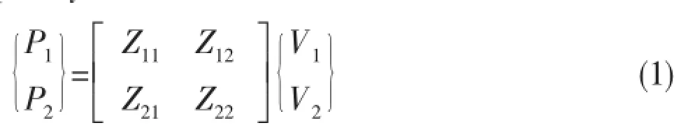
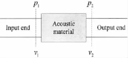
Fig.1 Two-port model
where P1and P2are the sound pressure at input end and output end,V1and V2are the volume velocity at input end and output end,Z11and Z22are the input impedance at input end and output end,Z12and Z21are the transfer impedance at input end and output end,respectively.
The impedance parameters could be determined at special boundary conditions.

To ensure the volume velocity at output end V2=0,the output end should be absolutely rigid,which means that the inertial impedance of output end should be infinity.Practically backing mass made from steel is used to represent the inertial impedance.
1.2 Impedance matrix of isotropic material
For isotropic material sample,the input impedance and transfer impedance are determined by Eqs.(6-7):

where HLis the thickness of sample,ρLis the density of sample,cLis the sound speed of sample.
1.3 Impedance matrix test method
The acoustic tube is shown in Fig.2,P1and P2are the sound pressure at input end and output end,V1and V2are the volume velocity at input end and output end.Two hydrophones are mounted on the wall of the tube,located at l and l+d before the input end to measure the sound pressure Pa1and Pa2,then the sound pressure P1and particle velocity V1of input end could be analyzed.The third hydrophone is mounted at the output end,just at the joints between sample and backing mass.The backing mass is treated as rigid backing,thus the particle velocity at output end V2≈0.

Fig.2 Scheme of acoustic test apparatus


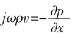

where ρωcωis the characteristic impedance of water.
Thus the pressure and particle velocity at location l could be:

The pressure and particle velocity at location l+d could be:

From Eqs.(12-13),the amplitudes of injective sound and reflective sound,i.e.A and Bcould be solved,thus the sound pressure P1and particle velocity V1at input end are easily obtained,thus the input impedance is:

The transfer impedance is

where H1=Pa2/Pa1,H2=Pa3/Pa1.
2 Apparatus design
The apparatus(Fig.3)is based on an acoustic tube with the same diameter,the lower end is a sound driver which produces sound wave,and the upper end is the material sample and backing mass.The whole acoustic tube is filled with pressured water.
2.1 Tube
The whole tube is made from stainless steel,the diameter of tube is 120 mm,and the wall thickness of tube is 60 mm,first,the tube could be pressured more than 6 MPa,second, the tube is rigid enough to make sure the plane wave exist(Fig.4).

Fig.3 Acoustic impedance test apparatus
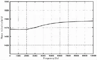
Fig.4 Sound speed of plane wave(0-order wave)
To seal the water from air,O-rings are used at both the driver and the top cover.Hydraulic connection locates at the lower part of the tube to fill water,pneumatic connection locates at the top cover to release the gas.
2.2 Driver
A long tonpilz driver(Fig.5)comprised by PZT rings is designed to get wide-band sound power in the tube.The injection sound pressure level is larger than 110 dB in 100-2 000 Hz,and the SNR is more than 20 dB.The driver could be working under the pressure 7 MPa.The driver and the tube are sealed with 2 O-rings.

Fig.5 The scheme figure and photo of driver
2.3 Backing mass
Generally,if the input impedance of backing mass(Fig.6)is ten times larger than the characteristic impedance of water,the backing mass could be treated as rigid backing.The thickness of the whole backing mass is 490 mm,the theoretically input impedance at 600-5 000 Hz is larger than 10 times of characteristic impedance of water,which is verified by using test under several pressure up to 3 MPa(Fig.7).
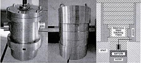
Fig.6 Steel backing mass
The input impedance of steel mass backing has a very little change with the change of environmental pressure.Because the characteristic impedance changes very little with pressure, so the effect of pressure on measurement system could be negligible.
2.4 Hydrophones
To limit the measurement uncertainty of transfer function,the distance of two hydrophones should be 0.1π<kd<0.8π,where k is the wavenumber,d is hydrophone distance.So the applicable frequency is 0.05c/d<f<0.4c/d.Four hydrophones and three kinds of distances(0.05 m,0.12 m and 0.4 m)are used to cover the whole measurement frequency span 100 Hz~2 kHz.
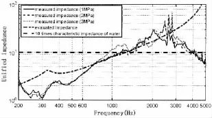
Fig.7 Theoretical and measured input impedances of multilayer steel backing
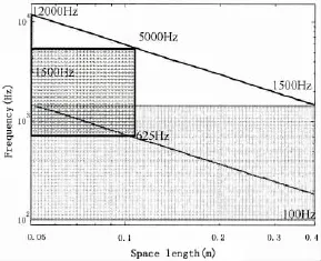
Fig.8 Relationship between hydrophone distance d and usable frequency span

Tab.1 Usable frequency span
3 Using impedance matrix to evaluate the absorption and transmission loss of underwater material
3.1 Absorption parameters using impedance
It is not intuitive to evaluate the properties of acoustic material from the impedance matrix.Usually the sound absorption coefficients and sound transmission loss are used to evaluate the properties of acoustic material,which could be converted from impedance matrix.
Suppose the acoustic material is isotropic material,d is the thickness,characteristic impedance is ρc,the impedance coefficients is:
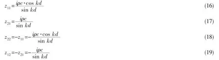
The surface impedance could be

where zbis the surface impedance of backing structure.
From the surface impedance,the reflection coefficients R is

Thus the sound absorption coefficients is

It is easy to know that,different backing corresponding to Zbwill bring different reflection coefficients.To evaluate the acoustic character of coating materials,the acoustic character should be taken into account.
3.2 Transmission loss parameters using impedance
The incident sound pressure piAand reflection sound pressure prAcould be obtained from the impedance matrix and the transmitted sound pressure pt(Fig.9).
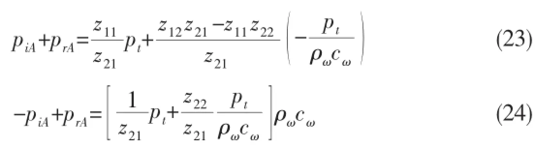
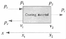
Fig.9 The acoustic parameters of coating material
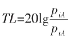
The sound transmission loss could be represented using impedance parameters.

4 Measurement results
4.1 Impedance matrix verification
To verify the method,two kinds of model made by isotropic material water and rubber are measured.The typical impedance matrix of water and rubber could be analyzed using their characteristic impedance.
The water models with three kinds of thickness 50 mm,100 mm and 200 mm,the rubber model with two kinds of thickness 50 mm and 200 mm,are tested(Fig.10).
The input impedance and transfer impedance of water layer(Fig.11)are highly in accordance with theoretical results above 500 Hz-1 kHz,below this frequency span,the test results go to bad because the backing mass is not rigid enough,the input impedance of backing mass does not meet the condition of‘rigid backing’(Figs.12-13).
When the water layer becomes thicker,the lower end of effective frequency span gets lower,the reason is that when the water layer becomes thicker,the phase shift induced by thetransmission in the water gets bigger,the relative measurement error induced by the phase error of test system gets smaller,thus the frequency becomes effective in lower frequency span.
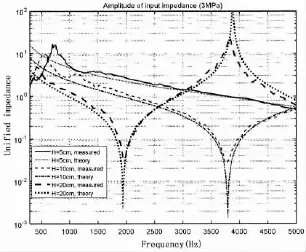
Fig.10 Measured input impedance of water
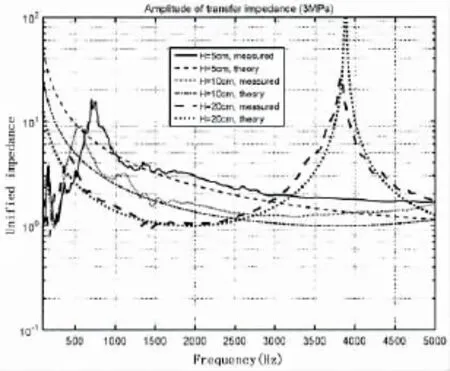
Fig.11 Measured transfer impedance of water
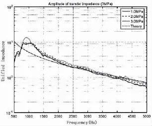
Fig.12 Theoretical and measured input impedance of rubber sample(50 mm thickness)
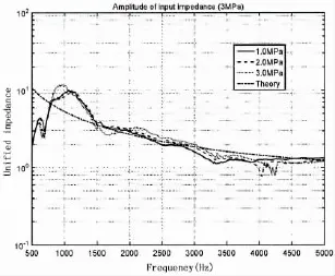
Fig.13 Theoretical and measured transfer impedance of rubber sample(50 mm thickness)
The impedance matrix of rubber sample(50 mm thickness)is measured,compared with theoretical impedance,they are well in accordance upon 800 Hz.
4.2 Absorption parameters verification
Using measured impedance matrix of rubber sample to calculate the sound absorption coefficients of rubber sample with steel backing,compared with the directly measured sound absorption coefficients.Measured and converted SAC are highly in accordance,the difference is less than 0.1 from 100 Hz to 5 kHz,and averaging error is less than 5%.
4.3 Transmission loss parameters verification
Water is acoustic transparent,the theoretical transmission loss for acoustic layer is 0 dB. The measurement results show that transmission loss for 10 cm thickness varies between-2 dB to 4 dB from 400 Hz to 5 kHz,especially,the measurement results are less than 1dB different from theoretical results from 2 000 Hz to 5 000 Hz.High pressure bring better results, the measurement results at 3 MPa have much less error than atmosphere.
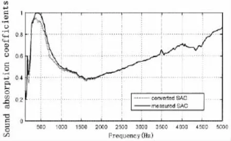
Fig.14 Measurement results and converted results of incident absorption coefficients
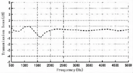
Fig.15 The measurement transmission loss for 10 cm thickness water layer
5 Conclusions
A method to measure the properties of underwater acoustic material under pressure based on acoustic impedance matrix is setup.Acoustic impedance matrix is measured to evaluate the absorption and transmission loss of underwater material.The test apparatus are well designed, especially for the tube,driver,backing mass and hydrophones.Isotropic material samples are tested to verify the test apparatus.Impedance matrix of acoustic coating material samples are measured to evaluate the absorption and transmission loss of samples,compared with theoretical results,the acoustic impedance method is verified.The impedance matrix could be used to evaluate the acoustic properties with different backings,it is a more efficient way than measuring the absorption coefficients or transmission loss directly.
[1]Chung J Y,Blaser D A.Transfer function method of measuring in-duct acoustic properties.I.Theory[J].JASA,1980,68 (3):907-913.
[2]Chung J Y,Blaser D A.Transfer function method of measuring in-duct acoustic properties.II.Experiment[J].JASA,1980, 68(3):914-921.
[3]Chung J Y,Blaser D A.Transfer function method of measuring acoustic intensity in a duct system with flow[J].JASA, 1980,68(6):1570-1577.
[4]Goodman J,43.30.Ky,43.85.Bh Underwater acoustic impedance measuring apparatus[P].Patent Number:4638275,1985. [5]Wilson P S.Sound propagation and scattering in bubbly liquids[D].Doctoral Dissertation,Boston University,2003.
[6]Wilson P S,Roy R A,Carey W M.An improved water-filled impedance tube[J].J Acoust.Soc.Am.,2003,113(6):3245-3252.
[7]Tao Z,Sybert A F.A Review of current techniques for measuring muffler transmission loss[C].SAE Noise and Vibration Conference,2003.
[8]John E Cole,Kyle Martini.A device for measuring the properties of acoustic materials at low frequency under pressure [R].AD Report,1994.
[9]Akoum M,Ville J M.Measurement of the reflection matrix of a discontinuity in a duct[J].J Acoust.Soc.Am.,1998,103 (5):2463-2468.
[10]Dalmont J P.Acoustic impedance measurement,Part I:A review[J].Journal of Sound and Vibration,2001,243(3):427-439.
[11]Dalmont J P.Acoustic impedance measurement,Part II:A new calibration method[J].Journal of Sound and Vibration, 2001,243(3):441-459.
《船舶力学》稿约须知
一、《船舶力学》(月刊)是中国船舶科学研究中心和中国造船工程学会联合主办的国内外公开发行的专业性学术期刊。它以繁荣科技文化,培养科研人才,促进科学技术向生产力转化,为社会主义现代化建设服务为宗旨。本刊着重刊登我国船舶与海洋工程力学界的科学著作、学术论文和创新研究成果以及有关振动与噪声、计算机应用、测试技术和研究综述等,是我国船舶与海洋工程力学界广大学者和中青年科技工作者的一个重要学术园地和论坛。本刊为中文核心期刊;中国科技核心期刊;RCCSE中国核心学术期刊;美国《工程索引》Ei核心期刊。2014年被评为中国精品科技期刊和百种中国杰出学术期刊。本刊同时刊登中、英文论文。欢迎国内外读者踊跃撰搞。
二、稿约要求
1.论点明确、条理清晰、文字简炼、论据充分、数据可靠。学术论文和综述文章一般不超过6000字(包括图、表);
2.欢迎使用打印稿(用A4纸单面打印,打印一式两份),如用网上投稿也应附有打印稿,标点准确,不要使用非正式公布的简化汉字。如用网上投稿,邮件发至:huanggr@cssrc.com.cn,同时邮寄二份打印稿以便与电子邮件发送稿校核;
3.计量单位一律采用《中华人民共和国法定计量单位》;
4.来稿要求附有中、英文摘要,中、英文关键词(Key words)3~8个,并放在论文首页。英文论文稿末页应附有中文题目、中文摘要及关键词;
5.请提供清晰准确的图、表。图中文字不宜太多。图题和表头应同时使用中英文表示。英文稿的图应插入文中,不要集中放在论文最后;……
猜你喜欢
杂志排行

船舶力学的其它文章
- Modal Pole Placement for Coupled Structural Acoustic System Based on Reduced Order Model
- Effect of Adiabatic Shear on Penetration Properties of Water-back Plate
- Safety Assessment of An Aging Offshore Jacket Platform by Integrating Analytic Hierarchy Process and Grey Clustering Method
- A Study on Connector Loads of Very Large Floating Structures near Islands and Reefs
- Three Dimensional Crack Path Prediction of Brittle Fracture in Weldment Under Fatigue Load
- Three-Dimensional Problem of the Compressible Water-gas Mixture Impacting on Rigid Plates