Forming mechanism of ink layer on the printing plate in inking process and influencing factors of its thickness①
2016-12-05ChuHongyan初红艳XuKangjianZhangXiaolinCaiLigang
Chu Hongyan(初红艳):Xu Kangjian:Zhang Xiaolin:Cai Ligang
(College of Mechanical Engineering and Applied Electronics Technology:Beijing University of Technology:Beijing 100124:P.R.China)
Forming mechanism of ink layer on the printing plate in inking process and influencing factors of its thickness①
Chu Hongyan(初红艳)*To whom correspondence should be addressed.E-mail:chuhongyan@bjut.edu.cnReceived on Sep.25,2015:Xu Kangjian:Zhang Xiaolin:Cai Ligang
(College of Mechanical Engineering and Applied Electronics Technology:Beijing University of Technology:Beijing 100124:P.R.China)
Ink layer thickness on the printing plate greatly influences uniformity of ink transferred to the substrates:which is an important indicator of printing quality:so the study of ink layer and its thickness is important for improving the quality of printing products.Ansys CFX is used here to build a model of ink fluid adhering to lower vibrator roller:form inking roller:and printing plate for analyzing ink transferring in inking process.Ink layer thickness on each position of the model is acquired to analyze the forming mechanism of ink layer on printing plate:as well as the influence of oscillation speed of lower vibrator roller and dot area percentage of plate on ink layer thickness of printing plate.It can be concluded that:in the case of fixed ink supplying amount:ink layer thickness increases along with the increasing of oscillation speed:and decreases when the dot area percentage is getting larger and the minimum is got when the dot area percentage is 100%.At last:experiment of plate inking on print ability tester verifies the correctness of the simulation analysis.
printing:oscillation:dot area percentage:ink layer thickness
0 Introduction
In the printing process of offset printing machine:ink coating on printing plate is transferred to substrate (for example:paper) under the printing pressure.Keeping ink stable:uniforml and with appropriate amount transferring to the substrate is the key to ensure high printing quality[1].The function of inking system of a printing machine is to uniformly and quantitatively transfer the ink from ink fountain to the printing plate’s surface.The inking system can be divided into ink supplying part:ink distributing part and inking part according to their functions.The contribution of inking part is to coat ink on image area of plate[2].All the factors such as printing pressure:printing speed:and uniformity of ink on ink distributing part as well as dot area percentage on plate greatly influence the inking process[3].
With the development of printing industry:research on inking part of an inking system has attracted more and more attentions.As shown in Ref.[4]:inking ratio of each form inking roller in inking system is changing dynamically in real operation.The dynamic change of inking ratio is related to the amount and arrangement structure of rollers in the inking system:and it affects the uniformity and consistency of the ink layer thickness of the plate surface.Hence:reasonable ink roller arrangement structure can improve dynamic change of inking ratio:reduce the fluctuation of ink layer thickness and:hence:improve the quality and stability of printing product.Inking ratio and dot area percentage have influence on each other:and ink layer thickness and inking ratio are closely related to dot area percentage on plate for the same inking system[5].
Due to the oscillation of roller:ink will expand from an ink area to the neighboring one:ink area with high dot area percentage requires a higher opening of ink key:and the ink layer thickness output by ink fountain is thick:so in the ink area with lower dot area percentage:the output ink layer thickness will be thinner.The comprehensive effect is that the ink area with low dot area percentage will get the expending ink from the area with a higher one[6].Ref.[7] uses Ansys CFX for fluid-solid coupling analysis of inking process when dot area percentage of plate is 100% and researches the influence of printing speed and pressure between form inking roller and printing plate on inking process.When the printing speed is fixed:with the increase of pressure between the form inking roller and the printing plate:the whole quantity of ink on plate has a tendency to decrease:and with the increase of printing speed:ink layer thickness on plate has a tendency to reduce.Ref.[8] put forward that in printing process:the change of ink layer thickness is reflected on printing plate.The ink layer thickness on the surface of plate has a certain relationship with the change of the number of turns of the plate cylinder rotation.
Although researches have been done in this area:there is few detailed analysis of the forming mechanism of ink layer thickness on the printing plate in inking process:especially analysis of the influence of oscillation speed of vibrator roller and plate dot area percentage on the ink thickness on plate.This paper uses ANSYS CFX to simulate inking process and experimental verification has been done:then the relationship between ink layer thickness and oscillation speed as well as dot area percentage is got.Research result has got important significance on color quality control in printing process.
1 Analysis of ink layer thickness in inking process
1.1 Building of ink fluid model
The structure of inking system in offset printing machine is shown in Fig.1:where ink is transferred through multiple rollers to the plate fastened to the plate cylinder.Building a complete inking system model for finite element analysis is difficult:and this paper focuses on analyzing the forming mechanism of ink layer on rollers and plate in inking process:so a simplified ink fluid model is built.The model includes the ink adhering to lower vibrator roller 5:form inking roller 10 as well as printing plate.Lower vibrator roller belongs to the ink distributing part:form inking roller and printing plate belong to the inking part.Lower vibrator roller is a hard roller:with negligible deformation in the process of squeezing and contacting with the form inking roller.What’s more:the lower vibrator roller is a driving roller:capable of circumferentially rotating and axial oscillating:which can spread the ink circumferentially and axially and have significant influence on printing production[2].The form inking roller is a driven soft roller with rubber layer covering its hard roller core:easy to deform under the contacting pressure and ink pressure in printing process.

Fig.1 inking system structure
As the plate includes image area and non-image area:and the non-image area doesn’t deliver ink:only ink fluid model of image area is built.Fig.2 shows the ink fluid model when dot area percentage is 50% (image and non-image area respectively occupies 50% of the whole ink area):and there is only the ink fluid model of image area on printing plate.The diameter of lower vibrator roller:form inking roller and plate cylinder are 60mm:49mm and 180mm respectively.The lower vibrator roller and plate cylinder counterclockwise rotate and form inking roller clockwise rotates.Ink thickness of the inlet of lower vibrator roller and plate are 0.06mm and 0.026mm respectively:and ink thickness of outlet is the same as that of outlet.When the form inking roller contacts with plate ink thickness of inlet is 0.05mm on image area:that of outlet is 0.038mm:and ink thickness of inlet and outlet on non-image area is 0.05mm.When form inking roller contacts with lower vibrator roller:ink layer thicknesses of inlet and outlet are both 0.06mm.Deformation of soft form inking roller and ink layer thickness of contacting area are determined by the method of fluid-solid coupling according to Ref.[9].

Fig.2 Ink fluid model
1.2 Mesh division and boundary condition
Ink transfer of the inking system is continuous in time and space:but computer can only deal with discrete magnitude.So in order to use computer to process the ink transfer which is a continuous process:the time-space discretization processing should be done to inking system[10,11].To facilitate the calculating and processing:the fluid model is divided with mesh which can realize the discretization of continuous ink system.Because ink layer thickness is very small and the mesh quality divided in CFX is poor:the fluid model mesh is divided in a meshing software ICEM CFD.The ink thickness of flow channel on contacting area is smaller than that in inlet and outlet areas.Refinement is done in the process of mesh division.Final mesh is shown in Fig.3.
Boundary condition is set.The fluid wall is no slip and insulation wall boundary.Printing speed is 3600r/h.Oscillation ratio is 1:3 which means:when the plate cylinder rotates 3 turns:vibrator roller vibrates one cycle[12].Three conditions with oscillation speed of 0:5πsin(0.67πt) and 10πsin(0.67πt) are analyzed in this paper.Boundary conditions are shown in Fig.4.The inner directed arrow represents the inlet of ink adhering to vibrator roller and printing plate:while the outside directed arrow represents the outlet of them.A closed model is adopted to described the ink model on form inking roller.

Fig.4 Boundary conditions
1.3 Result of numerical simulation
1.3.1 Ink fluid pressure
Fig.5 is the ink pressure nephogram in the whole cycle when the oscillation speed is v=5πsin(0.67πt).As shown in the figure:with the extension of time:ink pressure in the inlet of ink flow channel both on image and non-image area increases gradually.What’s more:ink pressure on the image area is obviously larger than that on non-image area.The ink fluid tension on image area is also larger than that on non-image area in the outlet area.

Fig.5 Ink pressure nephogram
1.3.2 Ink layer thickness in each position
Effective Ink layer thickness of each position in Fig.6 is extracted for each moment according to the method in Ref.[13].Figs 1 and 2 in Fig.6 represent the inlet of form inking roller and plate respectively:Figs 3and 4 represent outlet of them:and Fig.5 represents outlet of form inking roller when contacting with the vibrator roller.Multiple extractions should be done along axial direction in each position:and the average value of ink thickness in each position is calculated.Table 1 is the ink thickness of each position on image area in each moment when oscillation speed is v=5πsin(0.67πt):and T represents oscillation cycle.
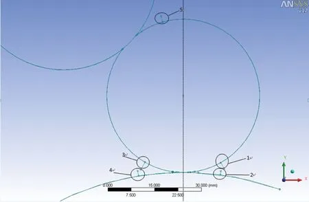
Fig.6 Ink layer location
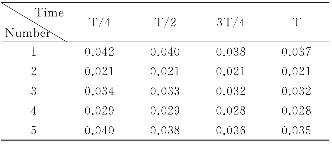
TimeNumberT/4T/23T/4T10.0420.0400.0380.03720.0210.0210.0210.02130.0340.0330.0320.03240.0290.0290.0280.02850.0400.0380.0360.035
It can be seen from Table 1:
(1) With the extension of time:ink layer thickness of position 2:as inlet of printing plate:remains unchanged:and ink layer thickness in other positions including position 1:3:4:5 on image area gradually decreases.This phenomenon is because that the ink adhering to the form inking roller on image area is constantly transferred to the plate and taken away by it:which leads to the decrease of the ink quantity in the whole ink structure.
(2) Comparing position 1 and 3:position 2 and 4 on image area for any moment:since form inking roller transfers ink to the printing plate:compared to the inlet of form inking roller (position 1):the ink layer thickness of outlet area (position 3) decreases:and compared to inlet of printing plate (position 2):the ink layer thickness of outlet area (position 4) increases.
2 Influence of oscillation speed on ink layer thickness of plate
Axial oscillation of vibrator roller can spread ink axially and diminish the of axial ink layer thickness difference of axial ink layer.When the dot area percentage of plate is set to 50%:influence of oscillation speed on ink layer thickness of plate is analyzed via 3 simulation analyses:v=0,v=5πsin(0.67πt) and v=10πsin (0.67πt).
2.1 Analysis of pressure
Ink pressure nephogram of the 3 situations at the time of t=T is shown in Fig.7.As shown in the figure:the larger the oscillation speed is:the higher the pressure will be.
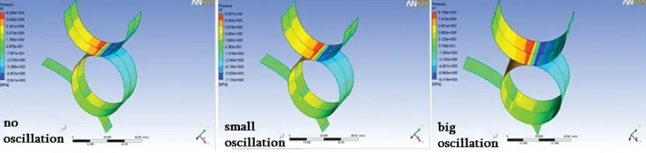
Fig.7 Ink pressure nephogram for different oscillation speed
2.2 Analysis of ink layer thickness
When the form inking roller and lower vibrator roller contact with each other and squeeze:ink will flow axially under the effect of vibrator roller’s axial oscillation.Table 2 shows the difference of ink layer thickness of location 3 and 5 on image and non-image area at the moment of 1/4 cycle.
As shown in Table 2:because the non-image area of form inking roller doesn’t transfer ink with printing plate:in position 3:the ink layer thickness of non-image area is larger than that of image area.Form inking roller will transfer ink with the lower vibrator roller,which moves at axial-direction and will pull the ink from non-image area having larger ink layer thickness to image area with smaller ink layer thickness (see the pressure distribution in Figs 5 and 7).So compared to position 3:ink layer thickness of position 5 increases on image area and decreases on non-image area.In other words:the difference of ink layer thickness between image and non-image area decreases.
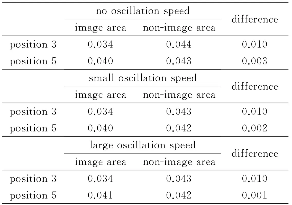
Table 2 Ink layer thickness of location 3 and 5 (mm)
It also can be seen from Table 2:with the increase of oscillation speed:the difference of ink layer thickness between image and non-image area in position 5 decreases.In other words:the oscillation effect of vibrator roller is getting stronger.
The relationship between ink layer thickness and oscillation speed in position 4:which is outlet of plate:in each moment:is shown in Fig.8.

Fig.8 Relationship between plate ink thickness and oscillation speed
It can be seen from Fig.8:the ink thickness in position 4 increases with the increase of oscillation speed.This is because that:position 2:as the inlet of plate:its ink thickness remains unchanged:while ink thickness of position 5 on image area increases with increase of oscillation speed (Table 2):which leads to the increase of ink thickness of position 1 on image area:that means:ink amount inking on the plate increases:which results in the growing of ink thickness in position 4.In non-image area of position 5:ink layer thickness decreases with the increase of oscillation speed:which leads to the decrease of thickness of position 1 on non-image area:and then leads to diminishing of that of position 3 (Table 2).
It also can be seen from Fig.8:regardless how much the oscillation speed is:with the extension of time:ink layer thickness of location 4 decreases.This is because in the inlet of the lower vibrator roller:the ink supplying amount is fixed:and with the time extending:the outlet of plate constantly takes ink away in the inking structure.
3 Influence of plate dot area percentage on ink layer thickness
3.1 Model building and mesh division
In order to facilitate the analysis:ink fluid model is simplified:that is:image area and non-image area are separated completely:and dot area percentage is 100% on image area and 0% on non-image area.If the dot area percentage of the whole ink area is 30%:then the image area will occupy 30% of the whole ink area:and the non-image area will occupy 70% of the whole.According to this method:ink fluid model of dot area percentage with 30%,40%,50%,60%,70%,100% is established.ICEM CFD is used for mesh division:as shown in Fig.9.
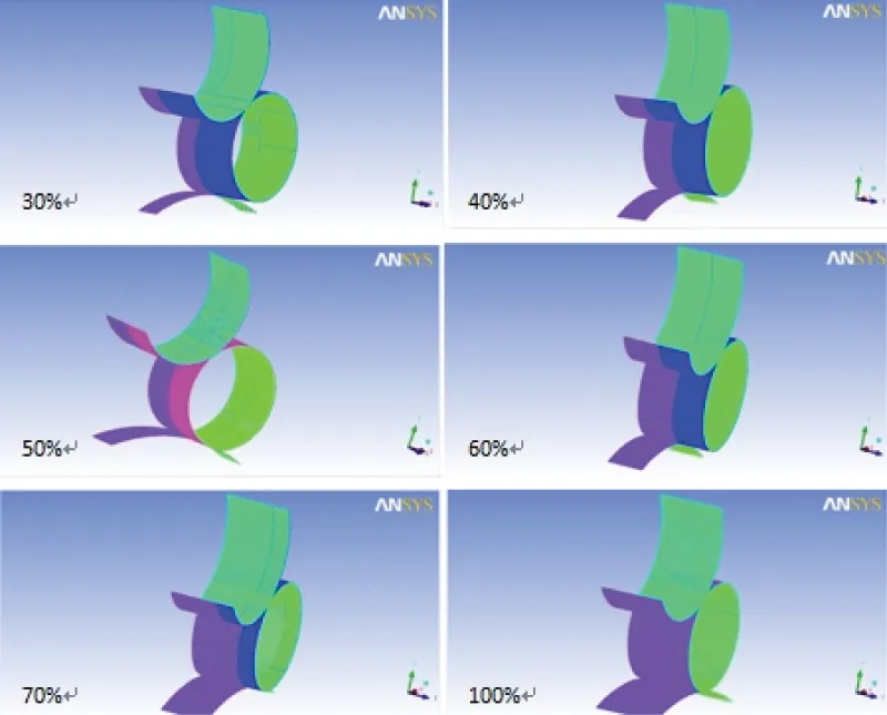
Fig.9 Ink fluid model mesh for different dot area percentage
3.2 Analysis of ink layer thickness
For the situation of oscillation speed v=10πsin(0.67πt):at the time of t=T:ink layer thickness of each position corresponding to different dot area percentage is shown in Table 3.
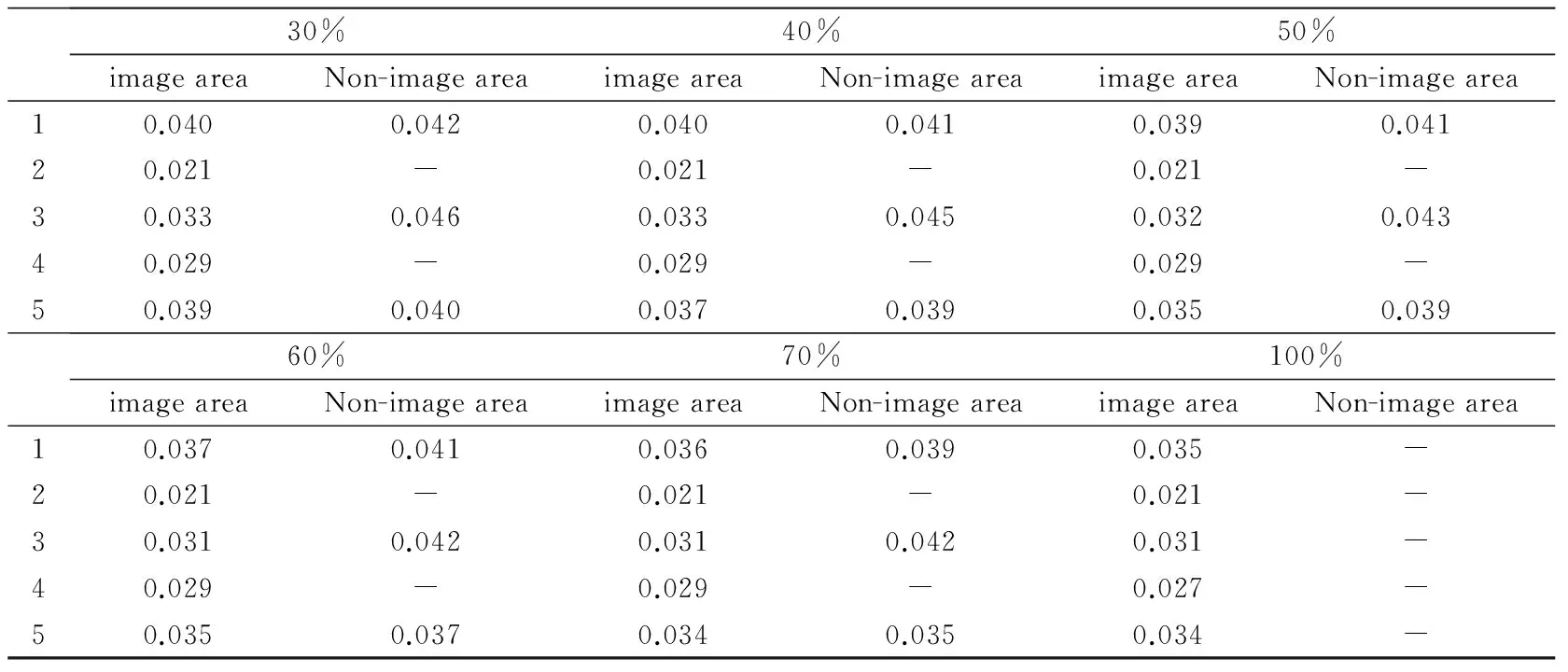
Table 3 Ink layer thickness of each positionfor different dot area percentage (mm)
(1) The relationship of ink layer thickness with dot area percentage in each position is shown in Fig.10.It can be seen from the figure:with the increase of dot area percentage:ink layer thickness of position 2 remains unchanged:and the thickness in other positions gradually decreases and it gets to the minimum value when the dot area percentage is 100%.This is because:with the increase of dot area percentage:the image area of plate enlarges:and when the form inking roller transfers ink with printing plate:more ink is taken out by the plate image area.The width of the whole ink area is fixed and the non-image area on plate will decrease with the increase of dot area percentage:then the amount of ink on the form inking roller will diminish:the amount of ink flowing to image area under the effect of oscillation of vibrator roller will decrease:which eventually leads to the reduction of ink layer thickness in position 1:3:4:5.
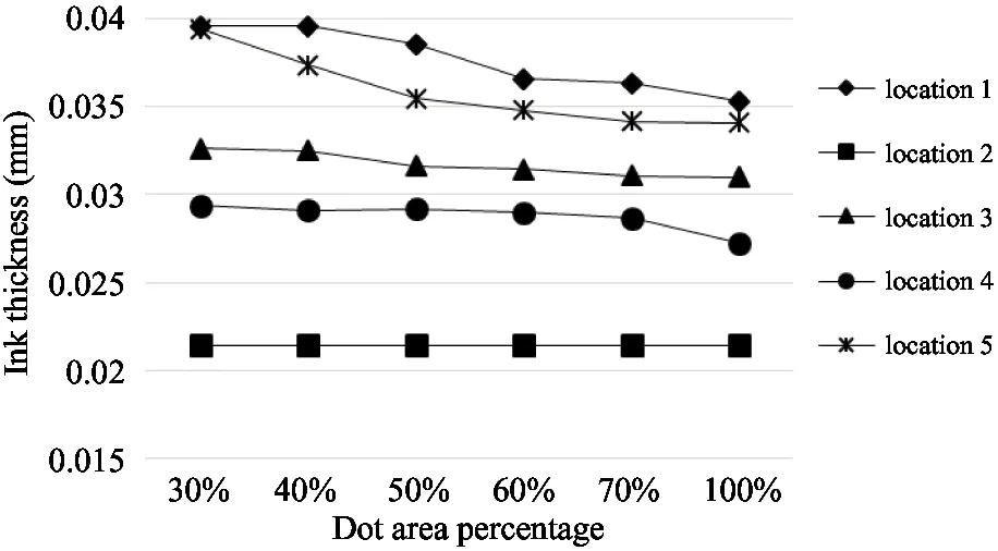
Fig.10 Relationship between ink layer thicknesses of image area and dot area percentage
(2) The relationship of ink layer thickness with dot area percentage in position1:3:5 on non-image area is shown in Fig.11.It can be seen from the figure:with the increase of dot area percentage:the thickness of each position on non-image area decreases too.This is also because:with the increase of dot area percentage:plate image area takes out more ink from form inking roller:the amount of ink of form inking roller on non-image area without transferring diminish:then under the effect of oscillation of vibrator roller:ink flows to the image area of form inking roller:which eventually leads to the reduction of ink layer thickness on the non-image area.

Fig.11 Relationship between ink layer thicknesses of non-image area and dot area percentage
4 Experiment analysis
Experiments include:(1) analyzing the influence of oscillation of vibrator roller on inking process and ink layer thickness on printing plate; (2) analyzing the impact of dot area percentage on ink layer thickness on the printing plate.
Ink layer thickness on plate is so thin that it’s not easy to be measured accurately.So in the experiment the ink layer thickness on plate is qualitatively analyzed through calculating the quality difference before and after printing.Main equipment used in the experiment includes printability tester (Fig.12) and precision balance.The adjustment range of pressure between rollers of printability tester is 0-1MPa:and oscillation speed can be “high” or “low”.The measurement range of precision balance is 200g:and its precision accuracy can be 0.1mg.
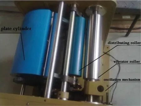
Fig.12 Printability tester
The printing plates used in experiment are allaluminum-made plate.In the process of making plate:image and non-image area are separated completely:and the image area occupies 30%:50%:70% and 90% of the whole plate respectively.
4.1 Oscillation influence experiment
Ink vibrator roller has only two speeds:“high” and “low”:3 inking experiments are done for each speed:and plate of 50% dot area percentage is chosen.Steps are as follows:(1) Fixing plate on plate cylinder; (2) Daubing ink to vibrator roller; (3) Starting up the tester:push distributing roller on the vibrator roller:the pressure between them is set to be 0.5MPa:and the vibrator roller speed is adjusted to be “low”; (4) After the ink fully transferring between two rollers:ink thickness of vibrator roller is measured; (5) Push the distributing roller on plate cylinder:and now it is the form inking roller:after fully inking:the plate is taken down.Adjust the speed to “high” after carrying on the above process in low speed for 3 times.Keeping the ink layer thickness of vibrator roller of Step (4) in each experiment uniform.The quantity of plate before and after inking is shown in Table 4.
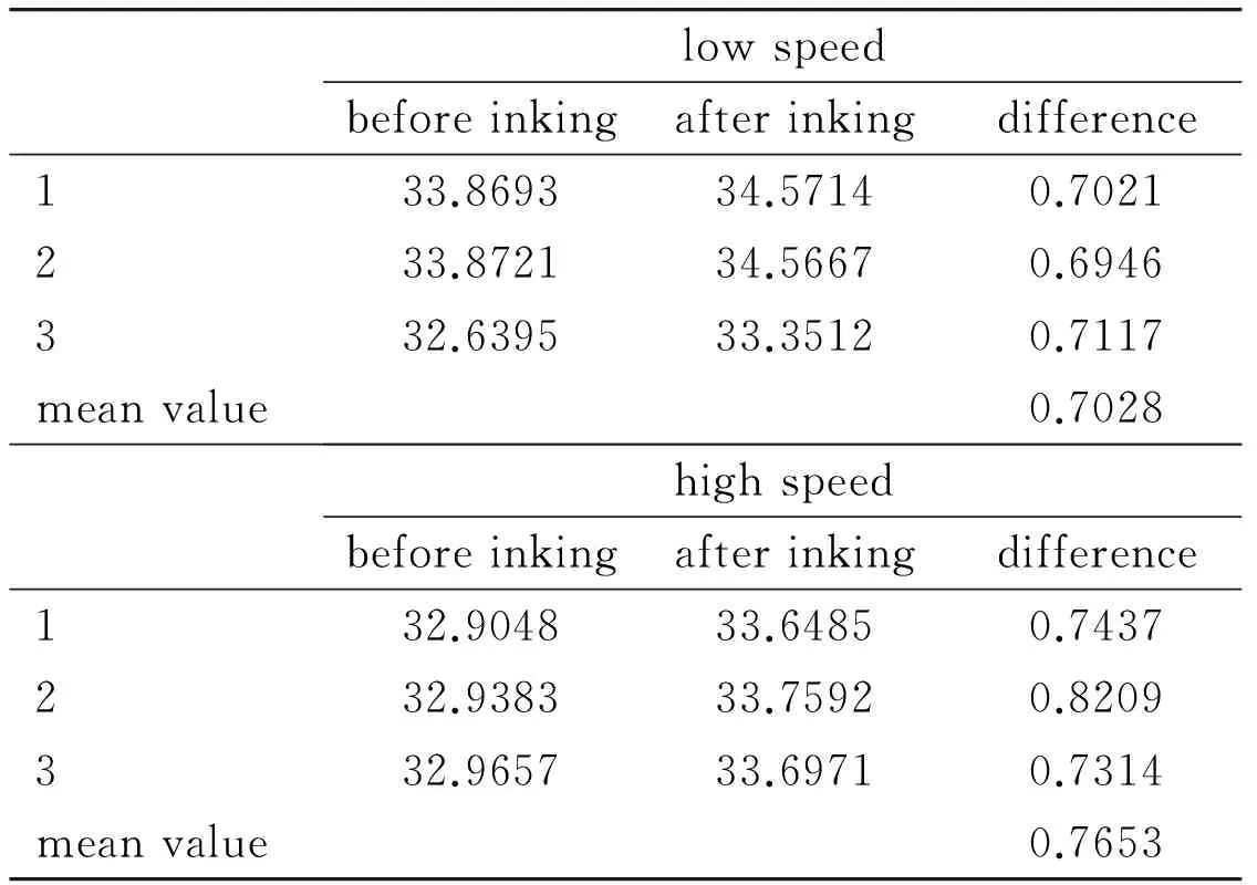
Table 4 Plate quality data for different oscillation speed (g)
It can be seen that when the oscillation speed is higher:the quantity of ink on the plate will be more:that is:high oscillation speed of vibrator roller is beneficial for ink transferring in inking process.It is consistent with the simulation result in Fig.8:which verifies the correctness of simulation analysis well.
4.2 Experiment of influence of plate dot area percentage
Plates with dot area percentage of 30%:50%:70%:90% are used:and the oscillation speed is adjusted to be “high”.The pressure between the form inking roller and the vibrator roller:the form inking roller and the plate cylinder are both 0.5MPa.The experimental procedures are identical to that described in Section 4.1.
Take down 6 plate patches with the same area from each printing plate and weigh them respectively.The data is shown in Table 5.The relationship between mean value of plate quality and dot area percentage is shown in Fig.13.
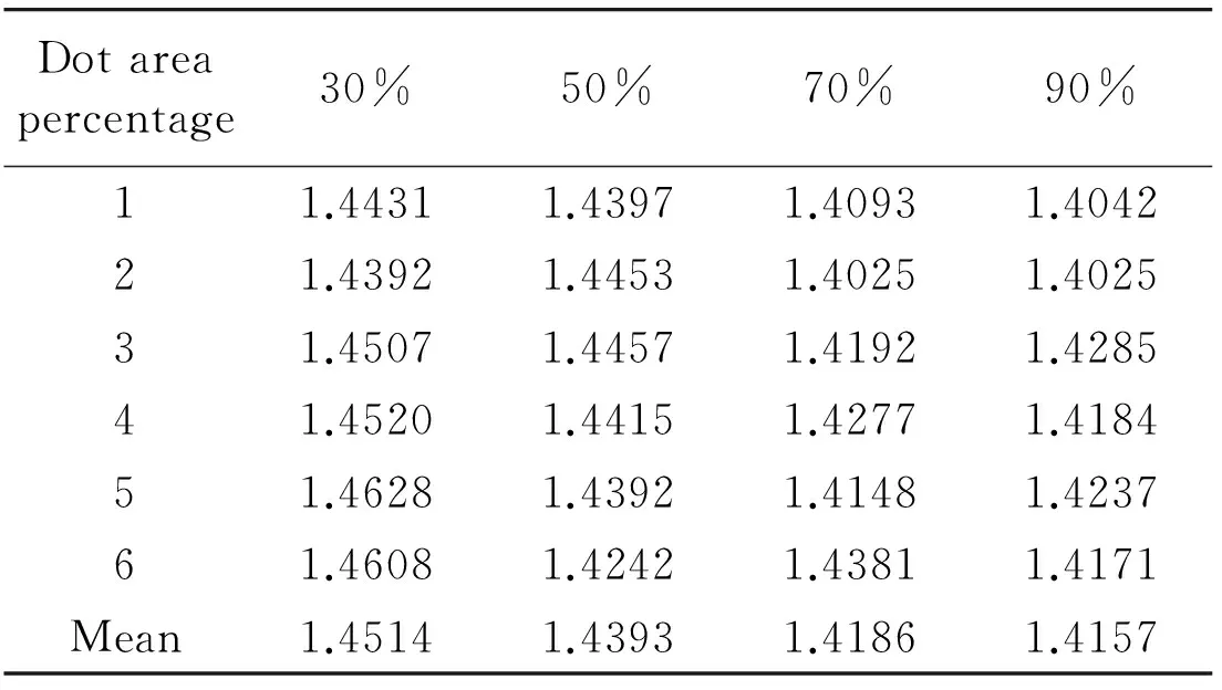
Table 5 Plate quality for different (g)
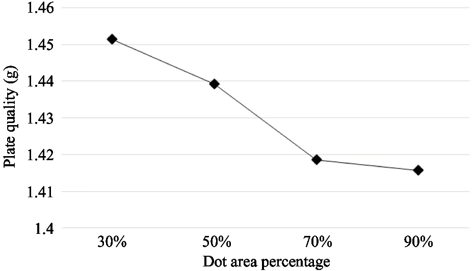
Fig.13 Relationship between plate quality and dot area percentage
As shown in Fig.13:the quality of plate decreases with the increase of dot area percentage:which means the ink layer thickness of plate decreases:which is consistent with Fig.10.Then the correctness of simulation analysis can be verified.
5 Conclusion
Model of ink fluid adhering to the lower vibrator:the form inking roller:and the printing plate is built.Ink layer thickness in each position of the model is got through ANSYS CFX simulation analysis.Influence of oscillation speed of vibrator roller and plate dot area percentage on the ink layer thickness of plate is analyzed:and the forming mechanism of ink layer on plate and influencing factors of its thickness are obtained.The experiment verifies the correctness of simulation analysis.
(1) With the extension of time:ink layer thickness in plate inlet remains unchanged:and other positions:including plate outlet:the thickness on image area all decreases:that is because the ink in the inking structure is constantly taken away by printing plate.That is to say:in the situation of no new ink supplied:the ink layer thickness on plate decreases constantly.
(2) Form inking roller transfers ink to printing plate:so in inking process:the ink layer thickness in outlet of form inking roller decreases compared to inlet:and ink layer thickness in outlet of plate increases compared to inlet.
(3) In the ink transferring process between the form inking roller and the lower vibrator roller:the axial movement of lower vibrator roller will pull the ink from the area of larger ink layer thickness to the area of smaller one.Hence:after transferring:the difference of ink layer thickness between image and non-image area of form inking roller will decrease.
(4) In the situation of same ink supplying amount and fixed printing speed:the ink layer thickness of plate increases with the increase of oscillation speed.
(5) In the situation of same ink supplying amount:fixed printing speed and oscillation speed of vibrator roller:the ink layer thickness on plate decreases with the increase of plate dot area percentage and eventually reaches a minimum value.
[1] Li J H:Wu H:Zhang Y.A brief analysis on the impact of ink performance on ink transfer rate.GuangdongPrinting:2014:5:35-36 (In Chinese)
[2] Zhang B Q.Brief analysis on inking mechanism of the offset printing.ChinaScienceandTechnologyInformation:2012:16:123-123 (In Chinese)
[3] Wu J M:Wu Q M.Research on consistency of ink film thickness of the offset printing.PackagingEngineering:2006:27(3):62-64 (In Chinese)
[4] Bai Z Y:Li H Y.Dynamic inking ratio and simulation analyses.PackagingEngineering:2010:31(9):96-98 (In Chinese)
[5] Wu J M:Wu Q M.Research on ink flow ratio based on percentage of coverage of rotary offset press.PackagingEngineering:2006:27(2):87-89 (In Chinese)
[6] Chou S M:Niemiro Ted.Computer simulation of offset printing:II.Effects of vibrator oscillation and image layout.TechnicalAssociationoftheGraphicArts:1997.94-118
[7] Chu H Y:Zhang X L:Cail G.Analysis of factors influencing inking process of offsetprinting machine.JournalofBeijingUniversityofTechnology:2015:41(6):816-822 (In Chinese)
[8] Pyryev Y:Krzyzkowski J.Parametric vibrations in offset printing units.Theoretical&AppliedMechanicsLetters:2012:2(4):60-63
[9] Chu H Y:Sun T.Analysis of ink flow channel between two rotating ink rollers.HighTechnologyletters:2015:21(3):253-260
[10] Pudas M:Hagberg J:Leppvuori S.Printing parameters and ink components affecting ultra-fine-line gravure-offset printing for electronics applications.JournaloftheEuropeanCeramicSociety:2004:24(10-11):2943-2950
[11] Zhang H Y:Zhang W X.Research on computer simulation of the offset inking system design.PackagingEngineering:2003:24(5):44-46 (In Chinese)
[12] Wang Z Y:Zhang L.Discussion on the problem of the speed of form inking roller.PrintingField:2006:5:72-73 (In Chinese)
[13] Chu H Y:Chen Z H:Su L:et al.Ink flow field and ink transferring rate on two ink rollers.JournalofBeijingUniversityofTechnology:2013:39 (3):359-365 (In Chinese)
Chu Hongyan:born in 1972.She received her Ph.D degrees in Beijing University of Technology:in 2003.She also received her B.S.and M.S.degrees from Jilin University of Technology in 1994 and 1997 respectively.Her research interests include sheet metal forming:production planning and scheduling:and printing colour quality control.
10.3772/j.issn.1006-6748.2016.03.009
①Supported by the National Key Technology Research and Development Program of China (No.2012BAF13B05-1) and National Natural Science Foundation of China (No.51105009).
猜你喜欢
杂志排行

High Technology Letters的其它文章
- Antenna selection based on large-scale fading for distributed MIMO systems①
- Real-time vehicle tracking for traffic monitoring systems①
- A survey of occlusion detection method for visual object①
- Concurrent processes scheduling with scarce resources in small and medium enterprises①
- Real-time video compression system design and hardware implementation based on multiple ADV212①
- MapReduce based computation of the diffusion method in recommender systems①