Remaining useful life prediction based on the Wiener process for an aviation axial piston pump
2016-11-23WngXingjinLinSiruWngShopingHeZhominZhngCho
Wng Xingjin,Lin Siru,Wng Shoping,He Zhomin,Zhng Cho,*
aSchool of Automation Science and Electrical Engineering,Beihang University,Beijing 100083,China
bBeijing Aeronautical Scienceamp;Technology Research Institute of COMAC,Beijing 102211,China
Remaining useful life prediction based on the Wiener process for an aviation axial piston pump
Wang Xingjiana,Lin Sirua,Wang Shaopinga,He Zhaominb,Zhang Chaoa,*
aSchool of Automation Science and Electrical Engineering,Beihang University,Beijing 100083,China
bBeijing Aeronautical Scienceamp;Technology Research Institute of COMAC,Beijing 102211,China
An aviation hydraulic axial piston pump's degradation from comprehensive wear is a typical gradual failure model.Accurate wear prediction is difficult as random and uncertain characteristics must be factored into the estimation.The internal wear status of the axial piston pump is characterized by the return oil flow based on fault mechanism analysis of the main frictional pairs in the pump.The performance degradation model is described by the Wiener process to predict the remaining useful life(RUL)of the pump.Maximum likelihood estimation(MLE)is performed by utilizing the expectation maximization(EM)algorithm to estimate the initial parameters of the Wiener process while recursive estimation is conducted utilizing the Kalman filter method to estimate the drift coefficient of the Wiener process.The RUL of the pump is then calculated according to the performance degradation model based on the Wiener process.Experimental results indicate that the return oil flow is a suitable characteristic for reflecting the internal wear status of the axial piston pump,and thus the Wiener process-based method may effectively predicate the RUL of the pump.
1.Introduction
An aviation axial piston pump acts as a core component of an aircraft hydraulic system,1,2providing high pressure hydraulic power for flight control surface actuation,landing gear con-trol,brake system control,etc.3Safety and reliability of the aviation axial piston pump is crucial to the whole aircraft system.4,5
Accurate and timely confirmation of remaining useful life(RUL)can ensure effective application of the axial piston pump under the premise of hydraulic system security and is necessary for on-condition maintenance of the aircraft hydraulic system.Statistically,over 80%of aviation axial piston pump failures originate from wear.Especially,nowadays,the aircraft hydraulic system is developing towards a high pressure trend,and as a result,the axial piston pump wear will become more and more significant due to hydraulic oil pollution.6Deterioration of inner friction pairs typifies gradual failure of the axial piston pump,acting as the main failure mode that determines the RUL of the pump.7,8Fault prognosis is necessary for predicting occurrence of wear failure and estimating the RUL of the axial piston pump to reduce maintenance expense,prolong useful life,and ultimately avoid accident occurrence.
Research related to RUL prediction for the piston pump is expansive.Chen et al.performed fault diagnosis from vibration signals after denoising based on second-generation wavelet and statistical methods.9Empirical mode decomposition and local mean decomposition were extensively applied to eliminate noise from the original vibration signal for extracting useful information.10A layered clustering multi-fault diagnosis method was then developed for the hydraulic axial piston pump.4Vibration signal originates from the inner friction pairs,but attenuates in the process of transmission to the pump casing while the upstream and downstream strong vibration signal of the axial piston pump could be modulated,significantly increasing difficulty of signalanalysis.The traditional feature extraction method based on vibration signal then is difficult to apply for wear status determination of the axial piston pump.11Eberle et al.monitored the wear status of a piston and a cylinder through increasing radioisotopic labels on the piston stroke center and adopting micro-test technology and surface activation and surface finish gauges.12The approach is accurate and highly sensitive;however,the process is complicated and difficult to implement.Iron spectrum data may also be utilized to analyze oil composition and particulate matter.13,14A database with abundant samples must be established to realize accurate wear status prediction due to pump models,friction pair materials,and hydraulic oil,and thus it is difficult to apply on the aviation hydraulic system.Frictional wear and cumulative damage theory were adopted in some research for modeling to calculate wear of the piston pump.15Erroneous judgment wear state recognition may occur due to the materials of a matching friction pair and the discrepancy between an actual load spectrum and a theoretical load spectrum.Contour graph was also adopted to determine the micromorphology of a friction pair's typical working area16;however,dismount of the pump was necessary and inconvenient for practical applications.
Return oil flow is a logical characteristic of the pump internal wear status as research indicates strong relevancy to clearance thickness of the inner friction pair in the axial piston pump.As wear gradually increases with pump working hours,the clearance between friction pairs increases followed by a corresponding increase in the return oil flow.
Gradual wear of the axial piston pump is typical and among internal components of the pump,and wear will mainly occur between the swash plate and the slipper,the slipper and the piston,the piston and the cylinder block,the cylinder block and the valve plate.17–19Clearance between moving surfaces in these four frictional pairs is not a fixed value due to differences and randomness of the complex temperature field,pressure field,and external loads.After wear occurs on any frictional pair within the pump,oil leakage will be produced causing effects on pressure field distribution and influencing wear characteristics of other frictional pairs.Therefore,strong randomness exists in the performance degradation path of the axial piston pump and it increases RUL prediction difficulty.
In order to address challenges resulting from random factors within fault prognosis and RUL prediction,the Wiener process is utilized to describe the performance degradation model. As an effective modeling technique to describe a random process,the Weiner process features superior calculation analysis properties to represent the performance degradation process.20,21Taking return oil flow as a characteristic,a nonlinear performance degradation model and an RUL prediction method based on the Wiener process are utilized in this study specific to axial piston pump wear failure.Under the framework of first-passagetime,a mathematical description of the RUL of the axial piston pump is defined.Parameter estimation method proposed by Si et al.will be used to estimate the initial parameters and the drift coefficient of the Wiener process of the performance degradation model.22Maximum likelihood estimation(MLE)is performed for initial parameters of the Wiener process by utilizing the expectation maximization(EM)algorithm.23Recursive filtering estimation is then conducted for the drift coefficient of the Wiener process by utilizing the Kalman filter method.The RUL of the axial piston pump could finally be predicted according to the Wiener process.Experimental results indicate that return oil flow is a suitable characteristic for reflecting the internal wear status of the axial piston pump and the prediction method based on the Wiener process may effectively predict the RUL of the aviation axial piston pump.
The remainder of this paper is organized as follows.In Section 2,fault mechanism of wear failure is analyzed for the axial piston pump;in Section 3,return oil flow is modeled and leakage flows of four frictional pairs are theoretically calculated;Section 4 details the performance degradation model and the RUL prediction method based on the Wiener process;in Section 5,experimental results are presented to demonstrate effectiveness of the proposed method;Section 6 presents final conclusions.
2.Wear failure in aviation axial piston pump
2.1.Structure and working mechanism of axial piston pump
The most extensively employed hydraulic pump in an aircraft hydraulic system is the swash plate type axial piston pump.24A pump with nine pistons is studied in this paper and the basic structure is illustrated in Fig.1.
The aeroengine drives the cylinder block to rotate through the drive shaft when the pump is working,allowing the pistons to rotate in tandem.The piston ball head is connected with a slipper ball socket and the slippers are compressed on the swash plate by a retainer plate.Consequently,when a piston moves from the bottom to top dead center along with the cylinder block at the clockwise direction,the fluid will be absorbed in the piston chamber through the suction slot of the valve plate;when the piston moves from the top to bottom dead center along with the cylinder at the clockwise direction,the fluid in the piston chamber will be discharged through the extraction slot of the valve plate.After the cylinder rotates for a cycle,each piston performs a back-and-forth reciprocating motion in the piston hole to complete fluid suction and fluid discharge.
2.2.Fault mechanism analysis of wear failure
2.2.1.Wear between swash plate and slipper
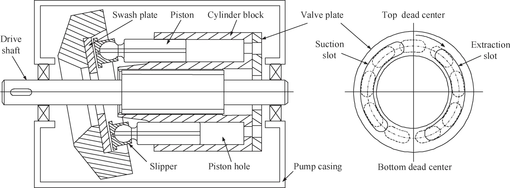
Fig.1 Structure of a swash plate type axial piston pump.
Wear caused by friction between the swash plate surface and the slipper bottom may be divided into two aspects.Firstly,pollutant mixing into hydraulic oil would cause particle wear on the two surfaces with wearing capacity relative to pollutant concentration(i.e.,higher pollutant concentration producing higher wearing capacity).Secondly,the instable slipper-pair oil film generated by internal pressure pulsation cannot effectively support the slipper,possibly leading to direct contact between the slipper bottom and the swash plate surface,resulting in adhesive wear.Eccentric wear on the slipper bottom,between the swash plate and the slipper,may also occur as it is generated by centrifugal force during the high speed movement process of the slipper boots.25
Wear between the swash plate and the slipper increases internal leakage and acts to decrease volumetric efficiency.Friction torque will also increase with aggravation of wear leading to mechanical efficiency reduction.
2.2.2.Wear between slipper and piston
The back-and-forth reciprocating motion of the pistons will drive the piston ball head to strike the slipper ball socket,causing deformation of the slipper ball socket with increasing pump work hours.During the autorotation process of the pistons,the piston ball head will then perform relative motion between the slipper ball sockets which will cause frictional wear between the two.
Consequently,the wear and deformation result in an increased clearance between the slipper ball socket and the piston ball head,generating inner leakage at the clearance.
2.2.3.Wear between piston and cylinder block
Wear between a piston and the cylinder block may be divided into two parts.Abrasive wear results from the hard pollutants in hydraulic oil while adhesive wear occurs as the piston is affected by centrifugal force and it is contacted by the piston hole of the cylinder block during the piston rotary process driven by the cylinder block.
Lubrication condition between the two can be classified into three categories including boundary lubrication,mixture lubrication,and hydrodynamic lubrication.Lubrication condition in the piston-pair varies among the three due to the influence of wear and random factors,and consequently,lubrication value for determining piston-pair wear status is minimal.Impact on the axial piston pump's overall performance from severe piston-pair effects wear manifests primarily in a reduction of volumetric efficiency resulting from internal leakage and diminishing mechanical efficiency as friction loss increases.
2.2.4.Wear between cylinder block and valve plate
The cylinder block will be compressed to the valve plate surface during the pump operation under the combined action of the hydraulic clamping force and the redundant squeezing force and will also complete a high-speed revolution around the valve plate surface with friction wear of the valve platepair resulting.These two reasons would result in frictional wear of the valve plate-pair.Hydraulic oil in the high pressure area and the piston pump features certain differential pressure,and consequently,the internal and external sealing zones around the waist shape holes will flow to the pump,generating internal leakage.Hard contaminated particles will mix into the oil fluid with increasing pump work time.The contaminated particles will enter the inside and outside oil sealing zones as well as the top and bottom dead areas,resulting abrasive wear between the internal and external oil sealing zones.On the other hand,adhesive wear would be also caused by the contact between the valve plate and the cylinder block surface under the influence of oil pressure pulsation,instable oil support film,and external load.
2.3.Fault mechanism analysis results
As analyzed in the last subsection,wear status in the aforementioned four frictional pairs will gradually accumulate with pump work time.As a result,the clearance between relative motion surfaces will increase to gradually increase internal leakage.It is well-known that the increment of internal leak may cause decreasing volumetric efficiency of the piston pump,and it will be finally reflected in the increment of return oil flow.
To this end,as a suitable indicator for internal wear status,return oil flow will be utilized to predict the RUL of the axial piston pump.
3.Return oil flow analysis and model based on wear failure
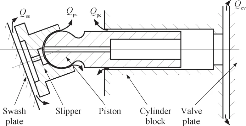
Fig.2 Main internal leakage flows of the axial piston pump.
Representation of frictional pairs wear in the axial piston pump is most obvious from increased leakage.26Fig.2 illustrates main leakage flows caused by the four frictional pairs,including leakage flow Qssgenerated through the flat plate gap between the swash plate and the slipper,leakage flow Qpsthrough the spherical gap between the piston ball head and the slipper ball socket,leakage flow Qpcthrough the concentric ring gap between the piston and the cylinder block,as well as leakage flow Qcvbetween the cylinder block and the valve plate.The Reynolds number of the leakage flow in the clearance of any frictional pair is typically minor.Leakage analysis of each frictional pair is then believed to be laminar flow between the clearances of frictional pairs.The leakage flow rate generated under each friction pair will be respectively calculated later.Then the system's total leakage flow,i.e.,return oil flow,is the sum of the leakage flows of the four frictional pairs.
3.1.Leakage flow Qssbetween swash plate and slipper
The matching structure between the swash plate and the slipper is displayed in Fig.3.High-pressure oil flows out from the parallel disc gap through the piston center hole and the slipper center hole and between the swash plate and the slipper bottom to form hydraulic support.The pressure difference between pressure P1in the slipper center hole and the return pressure P0will lead to differential pressure flow of hydraulic oil at the clearance hssbetween the swash plate and the slipper.15
According to the leakage theory of parallel discs,the leakage Qssbetween a single slipping boot and a tilting tray is27

where Rs1and Rs2are the inner and outer radii of the slipper bottom,and μ is the dynamic viscosity of fluid.
3.2.Leakage flow Qpsbetween slipper and piston
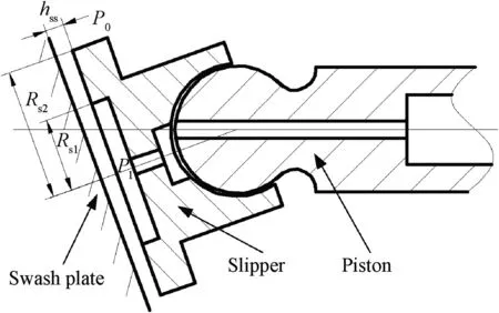
Fig.3 Matching structure between the swash plate and the slipper.
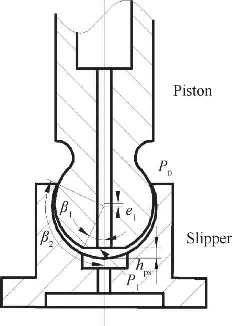
Fig.4 Matching structure of the piston ball head and the slipper ball socket.
The matching structure between the piston ball head and the slipper ball socket is displayed in Fig.4.A certain eccentric distance e1should exist between the piston ball head and the slipper ball socket to ensure free movement between the ball head and the ball socket.
Leakage flow Qpsin this frictional pair features two paths.One path is from the center hole of the piston,sequentially through the center hole of the slipper,entering the clearance between the slipper bottom and the swash plate.The other path of Qpsis to flow around the clearance hpsbetween the piston ball head and the slipper ball socket.27Consequently,the leakage flow Qpsbetween the piston ball head and the slipper ball socket is27:

where β1and β2are the effective arc lengths of the piston ball head and the slipper ball socket.
3.3.Leakage flow Qpcbetween piston and cylinder block
The matching structure of the piston and the cylinder block is shown in Fig.5.The piston will closely stick on the lateral side of the cylinder piston holes to form an eccentric annular aperture e2between the piston and the cylinder hole during the process of cylinder rotation.The piston chamber and the oil discharge chamber will connect following piston rotation to the high-pressure oil discharge area as driven by the cylinder.A pressure difference between the pressure in the piston chamber,namely,oil discharge pressure Ps,and the return pressure P0in the internal pump,will then generate.The pressure difference will result in the high-pressure hydraulic oil leaking to the pump casing along the eccentric annular aperture with clearance hpcbetween the piston and the cylinder.
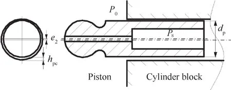
Fig.5 Matching structure of the piston and the cylinder hole.
When the piston enters the high-pressure oil discharge area,the piston will move in the direction of the valve plate in the cylinder piston hole discharging the hydraulic oil.Shearing action will then generate in the piston chamber.The directions of shear flow and differential pressure flow are contrary,and consequently,flow leakage Qpcbetween the piston and the cylinder piston hole is15:

where η=e2/hpcis the eccentricity ratio and dpis the diameter of the piston.l is the piston length remaining in the cylinder hole and may be expressed as:

where l0is the theoretical length of the piston,Rfis the distribution radius of pistons,γ is the angle of the swash plate,α is the angular position(when the piston is drawn back to the cylinder block completely,φ =0).Additionally,υ is the axial velocity of a single piston relative to the cylinder which may be analyzed as:

where ω is the angular velocity of the cylinder.
3.4.Leakage flow Qcvbetween cylinder block and valve plate
The structure of the valve plate in the axial piston pump is shown in Fig.6.For some piston pumps,the damping holes or triangular grooves will be set on both the top and bottom dead centers in order to reduce the outlet pressure pulsation.
In Fig.6,the rotation direction represents the motion direction of hydraulic oil which is driven by the cylinder under high speed rotation.Relative motion will take place between the cylinder block under high-speed rotation and the valve plate.Poor lubrication will initiate frictional wear and since the valve plate material is harder than the cylinder block material,friction will mainly occur on the cylinder block.Some pollutants in the hydraulic oil would generate three-body abrasive wear between the cylinder block and the valve plate,scratching the valve plate surface.The average clearance hcvbetween the cylinder block and the valve plate,following distribution pair wear,will increase and create increasing leakage flow into the high-pressure oil discharge area.10The leakage flow Qcvmay be calculated by:
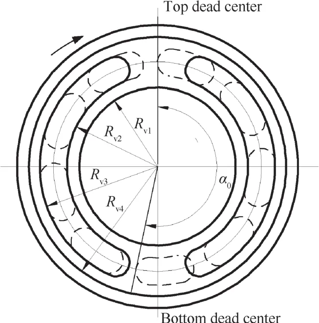
Fig.6 Structure of the valve plate.
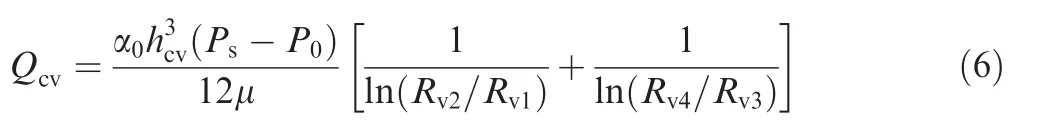
where Rv1and Rv2are the inner and outer radii of the internal oil sealing zone,Rv3and Rv4are the inner and outer radii of the external oil sealing zone,and α0is the distribution angle of the five pistons.
According to Eqs.(1)–(6),the total leakage flow(i.e.,return oil flow)Qplduring the piston pump operating process can be calculated.A strong correlation exists,as demonstrated,between the return oil flow Qpland the clearance of the corresponding frictional pair in the pump.
3.5.Analysis of the return oil flow of practical axial piston pump
According to the fault mechanism analysis of wear failure,the relationship between the return oil flow Qpland the internal wear of the pump is revealed.Variation tendency of the return oil flow at the smooth running stage,however,even for the pump with the same model,would be inconsistent.Fig.7 shows the actual variation tendencies of return oil flow of five practical aviation hydraulic axial piston pumps with the same model(operation conditions:input rotation speed:2000–4000 r/min;rated pressure:28 MPa).
It can be found from Fig.7 that the variation tendency of the return oil flow is relative to the wear failure process of a pump.Clearance thickness of frictional pairs will accumulate consistently due to increasing wear with a strong correlation then existing between the return oil flow and the wear process.It is clear that return oil flow will increase along with the pump work time and the wear process.Then return oil flow may indicate internal wear status of the axial piston pump and be utilized to predict the RUL of the pump.
However,we can find from Fig.7 that uncertainties still exist during the variation process of return oil flow.The uncertainties increase the difficulty of RUL prediction using return oil flow.In order to solve this issue,the Wiener process will be adopted by modeling the tendency of return oil flow and describing the pump performance degradation process.

Fig.7 Changing curves of return oil flow of five piston pumps.
4.Remaining useful life prediction based on Wiener process
4.1.Remaining useful life and performance degradation model based on Wiener process
In order to obtain an accurate estimation of the remaining useful life,both current performance degradation data and historical performance degradation data have to be comprehensively utilized to deduce the performance degradation path.
Combined with historical performance degradation data of the pump,the remaining useful life Trcan be defined as28:

where tiis the current time;Xftis the preset failure threshold;X0:i=[x0,x1,x2,...,xi]is the historical performance degradation data.The value is to be determined according to related products technical indicators and practical operation experiences.X(t)is utilized to represent return oil flow data of the axial piston pump at t and may directly reflect the internal wear status of the pump to determine performance degradation.
Wiener process increments feature properties of random distribution and mutual independence.These properties may effectively reflect the dynamic change features(i.e.,randomness and non-monotonicity)of the return oil flow along with the pump work time,describing the whole performance degradation process from normal operation to failure threshold.The Wiener process-based return oil 7flow variation process{X(t),t≥0}can be expressed as21:

where λ is the drift coefficient,synthetically reflecting the variation tendency of return oil flow and presenting the performance degradation trend of the pump;σBis the diffusion coefficient;B(t)is a standard Brownian motion;and σBB(t)presents the randomness of return oil flow variation.
In order to comprehensively apply historical performance degradation data,it is necessary to renew λ by using recursive update as:

where ε presents that the drift coefficient λ features randomness during the historical update process.The individual difference of the performance degradation path of the pumps with the same model is then reflected.Generally,it is assumed thatwherepresents the variance of ε.
4.2.MLE of initial parameters in Wiener process
Prior to predicting the RUL of the pump with the Wiener process,it is necessary to estimate the initial parameters,i.e.,the average μλ0and varianceof the initial drift coefficient λ0,the varianceof the drift coefficient observation error,and the diffusion coefficient σB.These four parameters would affect the drift coefficient and the diffusion coefficient respectively and exert significant influencing effects on the performance degradation path and RUL prediction.Precise estimation of the four parameters requires use of historical performance degradation data of the axial piston pump.The MLE method is to be completed utilizing the EM algorithm for the initial parameters of the Wiener process and the derivation process follows the method proposed in Ref.22
Firstly,define a vector for the desired parameters as:

Then,the joint probability density function p(X0:i|Θ)of Θ may be obtained under the historical performance degradation data X0:iat current time.In order to obtain the MLE of Θ,firstly calculate the logarithm to obtain the log-likelihood function as:

Then,the MLE^Θ of Θ may be given as:

The four parameters in vector Θ are implicit variables for the historical performance degradation data X0:i,and thus it is impossible to directly obtain explicit expressions of these parameters from the historical performance degradation data X0:i.Fortunately,the drift coefficient of the historical performance degradation data X0:ican be utilized to attain the MLE of Θ.
Let Ω0:i=[λ0,λ1,λ2,...,λi]represent the historical data of the drift coefficient λ from initial time t0to current time ti.Assuming that event A is the historical drift coefficient Ω0:iunder the condition of Θ,namely,p(A)=p(Ω0:iΘ|);event B is the historical performance degradation data X0:iunder the condition of Θ,namely,p(B)=p(X0:iΘ|);thus it may be assumed that in case of concurrence of event A and event B,p(AB)=p(X0:i,Ω0:iΘ|)presents the historical performance degradation data X0:iand the historical drift coefficient Ω0:iunder the condition of Θ;in case of event A on the premise of event B,p(A B|)=p(Ω0:iX0:i| ,Θ)indicates that the historical drift coefficient Ω0:ican be obtained based on the historical performance degradation data X0:iunder the condition of Θ.According to the conditional probability equationmay be derived as:
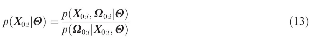
Taking the logarithmic form from Eq.(13),we have:

The first item lg[p(X0:i,Ω0:iΘ|)]in Eq.(14)represents the jointed logarithmic likelihood function of the historical performance degradation data X0:iand the historical drift coefficient Ω0:i,marked as φi(Θ).The estimation of Θ is to be realized relying on the function.
Then calculate the mathematical expectationof the jointed logarithmic likelihood function as:

Then unfolding φi(Θ),we can obtain:
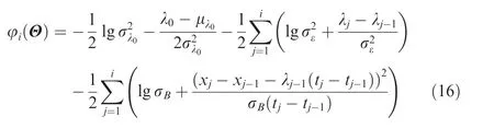
Substituting Eq.(16)into Eq.(15)leads to:
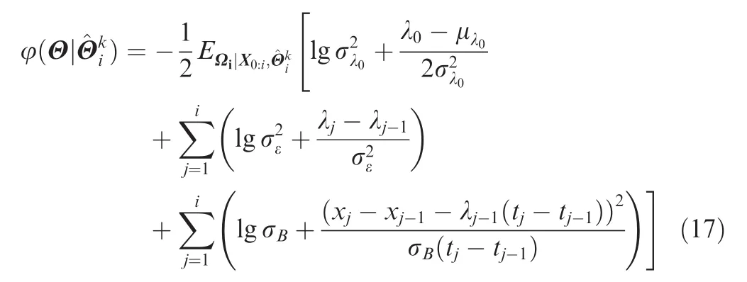
There are several values to be derived from Eq.(17),includingandThese three unknown mathematical expectations are to be calculated referring to the Kalman filter backward recursion from current time to initial time.If,then the following may be derived:
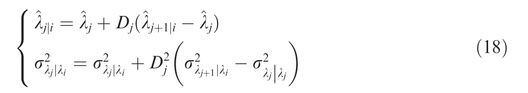
The covariance of the drift coefficient at current time is:

where Kiis the Kalman gain.Then the covariance shall be backward recurred as:

Perform the loop iteration to initial moment.Ultimately,the following may be obtained:
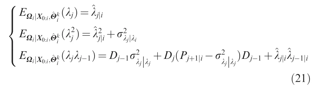
Substituting Eq.(21)into Eq.(17),the mathematical expectation of the jointed logarithmic likelihood function can be obtained.After maximizing the process,the values of μλ0,,and σBfor next step iteration may be expressed as22:parameter of each corresponding moment is λj(j=0,1,2,...,i).The drift parameter λ then may be estimated through recurrence filtering by utilizing the performance degradation data X0:i.22
Based on the Bayesian inference algorithm,the posterior probability density functionof the drift parameter λ may be calculated by utilizing the prior probabilityof the drift parameter λ as follows22:
Strong tracking filter was utilized to execute the recursive estimation for the drift coefficient.22In this study,we utilize the Kalman filter algorithm to estimate the drift coefficient λ.
Based on the Kalman filter algorithm,29,30the recursive estimation algorithm of the drift coefficient λ at current time by utilizing the historical data is shown in the following:
Step 1:Perform initialization for the drift parameter λ according to the MLE results.Set the initial value of the drift parameter λ at t0as μλ0with variance
Step 2:Calculate the varianceof the drift parameter λiat current time by utilizing the optimal estimate varianceof the drift parameter λi-1at ti-1and the population varianceof the drift coefficient λ as:

Step 3:Calculate the Kalman gain at current time as:

Step 4:Calculate the optimal estimation^λiof the drift coefficient λiat current time based on the Kalman gain Ki:

Step 5:Calculate the variance of the optimal estimation of the drift coefficient λiat current time based on the Kalman gain Ki.

After obtaining the variance of the optimal estimation^λiof the drift coefficient λi,the optimal estimation and variance of

Perform re-estimation of Θ by using Eq.(22)until reaching the convergence requirements.
4.3.Recursive filtering estimation of the drift coefficient
The performance degradation data from initial time t0to current time tiisX0:i=[x0,x1,x2,...,xi]and the drift the next moment of the drift parameter λi+1may be calculated by repeating Step 2 to Step 5.
The Bayesian inference31based on the Kalman filter algorithm features a rapid calculation ability and superior precision to estimate parameters with a posterior probability that obeys normal distribution.
Synthesizing the RUL definition in Eq.(7)and the optimal estimation^λias well as the variance σλiλi|after recursive estima-tion,the probability density function of the RUL at tican be calculated as:
where Φ(.)is the standard normal cumulative distribution function.
According to Eq.(29),the mathematical expectation E(t X0:i| )of the RUL at tibased on the historical performance degradation data X0:ican be obtained as22

The remaining useful life(RUL)at current time may be calculated from Eq.(28)after obtaining the optimal estimation^λiand its standard deviation σλiλi|of the drift coefficient λiat current time by adopting recursive filtering estimation.
5.Example verification
In order to verify the effectiveness of the proposed RUL prediction method,full life cycle experiments are performed on a certain type of aviation axial piston pump.A turbine flow sensor is installed on the return oil pipe to measure the return oil flow of the tested pump.Full output flow condition(input rotation speed:4000 r/min)is adopted to accelerate the wear speed of the pump and the return oil flow data is recorded every five hours.According to the design parameters of this type of axial piston pump,the pump is considered as a total failure in case of the return oil flow exceeding 2.8 L/min.
Fig.8 shows the actual sequence distribution of the return oil flow during the whole experimental process and illustrates that with increasing time,the continuously increasing return oil flow proves continuous wear of the pump and consistent increase of internal leakage.The return oil flow reaches the failure threshold of 2.8 L/min at the 237th point(1180 h),indicating the pump has completely failed.

Fig.8 Actual return oil flow data within the full life cycle.
After obtaining the return oil flow data at a specific moment ti,the initial parameters of the Wiener process can be estimated by the MLE algorithm while the drift coefficient can be estimated utilizing Kalman recursive filtering estimation.The drift coefficient estimation of the performance degradation model,established based on the Wiener process of return oil flow of the tested pump,is displayed in Fig.9.Few errors exist between the estimated values and the actual data with errors comparatively stable and not increasing along with change of time.
The amount of the return oil flow data acquired increases consistently with increasing time thus to ensure that the parameter estimation is converged.The RUL and its probability density function at a specific time can be calculated after completing the parameters estimation by utilizing current historical data.Probability density functions of the RUL of the test pump are calculated at the 110th,160th,190th,210th,230th,and 237th observation points(see Fig.10).
From Fig.10,it can be found that the actual RUL of the tested pump is within the range of the probability density function of the RUL at any corresponding point.The probability density function of the RUL becomes increasingly precise with gradual accumulation of the observed return oil flow data for the tested pump,which indicates that the nondeterminacy of the RUL becomes increasingly lower.The performance degradation path is then predicted as the accuracy of parameter estimation gradually increases with more return oil flow historical data.

Fig.9 Drift coefficient value and its error obtained by utilizing the Kalman filter algorithm.
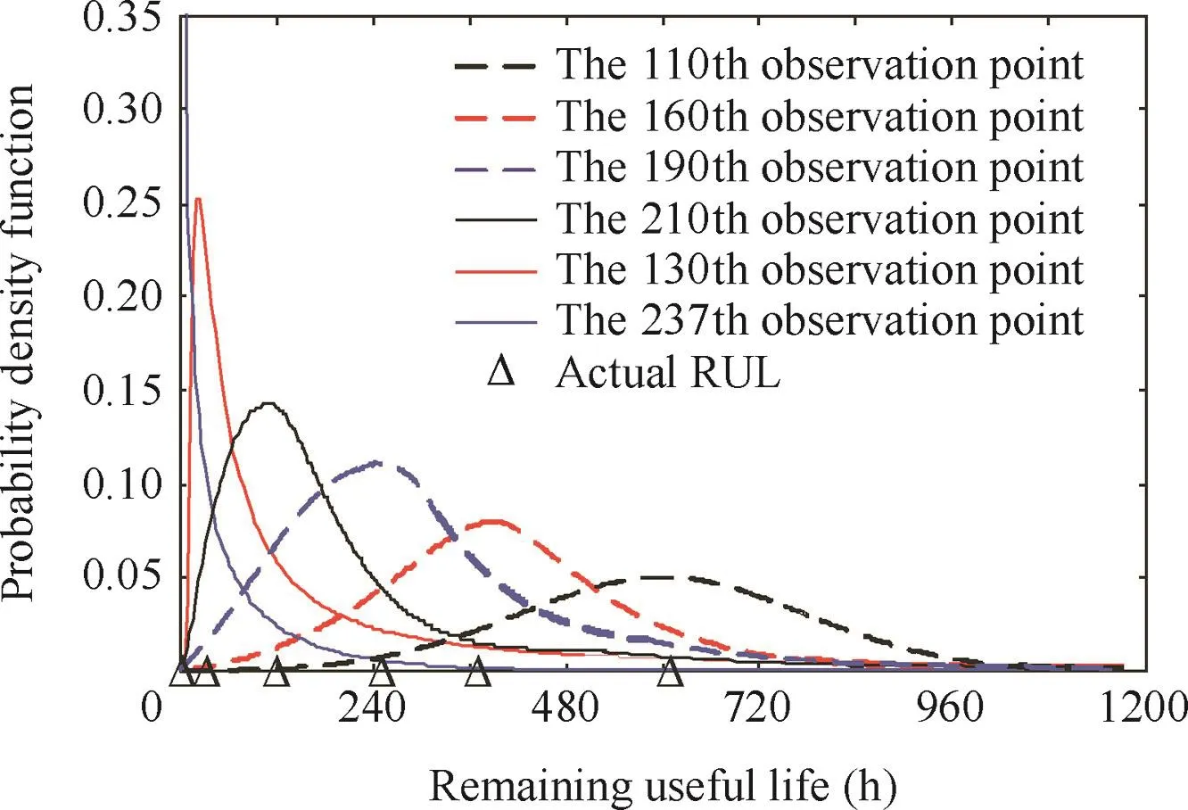
Fig.10 Probability density functions of the RUL at different observation points.
6.Conclusions
An RUL prediction method based on the Wiener process has been proposed in this study for the aviation hydraulic axial piston pump.The main contributions of this research work are:
(1)Leakage flows of four frictional pairs are calculated based on the fault mechanism analysis of wear failure.Mathematical models and experimental results indicate that return oil flow is a suitable characteristic for reflecting the internal wear status of the axial piston pump;
(2)The Wiener process-based method may effectively predicate the RUL of the aviation axial piston pump,even if unexpected uncertainties always exist during the variation process of return oil flow.The Wiener process initial parameters of the performance degradation model are estimated by the MLE algorithm and the drift coefficient is estimated by recursive estimation based on the Kalman filter method.Experimental results validate the effectiveness of the proposed Wiener process-based aviation hydraulic axial piston pump RUL prediction method.
Acknowledgments
This work was supported by the National Natural Science Foundation of China(No.51305011),the National Basic Research Program of China(No.2014CB046402),and the 111 Project of China.
1.Li C,Jiao Z.Thermal-hydraulic modeling and simulation of piston pump.Chin J Aeronaut 2006;19(4):354–8.
2.Wang Z,Lu C,Wang Z.Chaotic information-geometric support vector machine and its application to fault diagnosis of hydraulic pumps.J Vibroeng 2014;16(2):1033–41.
3.Wang X,Wang S.High performance adaptive control of mechanical servo system with LuGre friction model:identification and compensation.J Dyn Syst Meas Control 2012;134(1):011021.
4.Du J,Wang S,Zhang H.Layered clustering multi-fault diagnosis for hydraulic piston pump.Mech Syst Signal Processing 2013;36(2):487–504.
5.Han L,Wang S,Zhang C.A partial lubrication model between valve plate and cylinder block in axial piston pumps.Proc Inst Mech Eng,Part C:J Mech Eng Sci 2015;229(17):3201–17.
6.Ge W,Wang S.Wear condition prediction of hydraulic pump.J Beijing Univ Aeronaut Astronaut 2011;37(11):1410–4 Chinese.
7.He Z,Wang S.Wear status recognition of piston pump based on side frequency relative energy summation.J Beijing Univ Aeronaut Astronaut 2014;40(2):183–7 Chinese.
8.Ma J,Chen J,Li J,Li Q,Ren C.Wear analysis of swash plate/slipper pair of axis piston hydraulic pump.TribolInt 2015;90:467–72.
9.Chen H,Chua PS,Lim G.Vibration analysis with lifting scheme and generalized cross validation in fault diagnosis of water hydraulic system.J Sound Vib 2007;301(3):458–80.
10.Wang Y,He Z,Xiang J,Zi Y.Application of local mean decomposition to the surveillance and diagnostics of low-speed helical gearbox.Mech Mach Theory 2012;47:62–73.
11.Lee J,Wu F,Zhao W,Ghaffari M,Liao L,Siegel D.Prognostics and health management design for rotary machinery systemsreviews,methodology and applications.Mech Syst Signal Processing 2014;42(1):314–34.
12.Eberle D,Wall C,Treuhaft M.Applications of radioactive tracer technology in the real-time measurement of wear and corrosion.Wear 2005;259(7):1462–71.
13.Peng Z,Kessissoglou N.An integrated approach to fault diagnosis of machinery using wear debris and vibration analysis.Wear 2003;255(7):1221–32.
14.Wang H,Gong L,Zhao W,Zhao H.Extended NGM(1,1,K)model and its application to spectral prediction of military launch vehicle hydraulic system.Appl Mech Mater 2014;454:90–3.
15.Nie S,Huang G,Li Y.Tribological study on hydrostatic slipper bearing with annular orifice damper for water hydraulic axial piston motor.Tribol Int 2006;39(11):1342–54.
16.Lim H,Lee M,Kim P,Park J,Jeong S.Improvement of surface hardness of duplex stainless steel by laser shock hardening for the application to seawater desalination pump.Desalin Water Treat 2010;15(1–3):43–7.
17.Yamaguchi A,Matsuoka H.A mixed lubrication model applicable to bearing/seal parts of hydraulic equipment.J Tribol 1992;114(1):116–21.
18.Kazama T,Yamaguchi A.Application of a mixed lubrication model for hydrostatic thrust bearings of hydraulic equipment.J Tribol 1993;115(4):686–91.
19.Kazama T,Yamaguchi A.Experiment on mixed lubrication of hydrostatic thrust bearings for hydraulic equipment.J Tribol 1995;117(3):399–402.
20.Whitmore G,Schenkelberg F.Modelling accelerated degradation data using Wiener diffusion with a time scale transformation.Lifetime Data Anal 1997;3(1):27–45.
21.Tseng ST,Tang J,Ku IH.Determination of burn-in parameters and residual life for highly reliable products.Nav Res Log 2003;50(1):1–14.
22.Si X,Wang W,Hu C,Chen M,Zhou D.A Wiener-process based degradation model with a recursive filter algorithm for remaining useful life estimation.Mech Syst Signal Pr 2013;35(1):219–37.
23.Dempster AP,Laird NM,Rubin DB.Maximum likelihood from incomplete data via the EM algorithm.J R Stat Soc Ser B(Methodol)1977;39(1):1–38.
24.Guan C,Jiao Z,He S.Theoretical study of flow ripple for an aviation axial-piston pump with damping holes in the valve plate.Chin J Aeronaut 2014;27(1):169–81.
25.Jeong HS,Kim HE.On the instantaneous and average piston friction of swash plate type hydraulic axial piston machines.KSME Int J 2004;18(10):1700–11.
26.Bergada J,Kumar S,Davies DL,Watton J.A complete analysis of axial piston pump leakage and output flow ripples.Appl Math Model 2012;36(4):1731–51.
27.Ivantysyn J,Ivantysynova M.Hydrostatic pumps and motors:principles,design,performance,modelling,analysis,control and testing.1st ed.New Delhi:Tech Books International;2003 p.55–68.
28.Huang R,Xi L,Li X,Liu CR,Qiu H,Lee J.Residual life predictions for ball bearings based on self-organizing map and back propagation neural network methods.Mech Syst Signal Processing 2007;21(1):193–207.
29.Ridder C,Munkelt O,Kirchner H.Adaptive background estimation and foreground detection using Kalman-filtering.Proc Int Conf Recent Adv Mechatron 1995;193–9.
30.Godard D.Channel equalization using a Kalman filter for fast data transmission.IBM J Res Dev 1974;18(3):267–73.
31.Jones SK,Cavin III RK,Reed WM.Analysis of error-gradient adaptive linear estimators for a class of stationary dependent processes.IEEE Trans Inf Theory 1982;28(2):318–29.
Wang Xingjianreceived his Ph.D.and B.E.degrees in mechatronics engineering from Beihang University,China in 2012 and 2006,respectively.From 2009 to 2010,he was a visiting scholar in the School of Mechanical Engineering at Purdue University,West Lafayette,IN,U.S.He is currently with the School of Automation Science and Electrical Engineering at Beihang University,Beijing,China.His research interests are nonlinear control,active fault tolerant control,fault diagnostic,and fault prognostic.
Lin Sirureceived her B.E.degree in mechatronics engineering from China University of Miningamp;Technology,Beijing,China in 2015.Now she is a Master's student in the School of Automation Science and Electrical Engineering at Beihang University,Beijing,China.Her research interests are fault diagnostic,prognostic,and health management.
Wang Shaopingreceived her Ph.D.,M.E.,and B.E.degrees in mechatronics engineering from Beihang University,China,in 1994,1991,and 1988,respectively.She has been with the School of Automation Science and Electrical Engineering at Beihang University since 1994 and was promoted to the rank of professor in 2000.Her research interests are engineering reliability,fault diagnostic,prognostic and health management,as well as active fault tolerant control.
He Zhaominreceived his Ph.D.and M.E.degrees in mechatronics engineering from Beihang University in 2013 and Qingdao University of Scienceamp;Technology in 2008,respectively.He is currently with Beijing Aeronautical Scienceamp;Technology Research Institute of COMAC.His research interests are fault diagnostic,prognostic,and health management.
Zhang Chaoreceived his Ph.D.and B.E.degrees in mechatronics engineering from Beihang University in 2014 and 2008,respectively,and then became an instructor there.His main research interests are reliability testing,performance degradation,and fault diagnosis of hydraulic systems.
22 August 2015;revised 11 December 2015;accepted 11 December 2015
Available online 21 December 2015
Axial piston pump;
Hydraulic system;
Remaining useful life;
Return oil flow;
Wear;
Wiener process
Ⓒ2016 Production and hosting by Elsevier Ltd.on behalf of Chinese Society of Aeronautics and Astronautics.This is an open access article under the CC BY-NC-ND license(http://creativecommons.org/licenses/by-nc-nd/4.0/).
*Corresponding author.Tel.:+86 10 82338917.
E-mail address:cz@buaa.edu.cn(C.Zhang).
Peer review under responsibility of Editorial Committee of CJA.
杂志排行
CHINESE JOURNAL OF AERONAUTICS的其它文章
- Optimization on cooperative feed strategy for radial–axial ring rolling process of Inco718 alloy by RSM and FEM
- Measuring reliability under epistemic uncertainty:Review on non-probabilistic reliability metrics
- Optimum blade loading for a powered rotor in descent
- Experimental study of ice accretion effects on aerodynamic performance of an NACA 23012 airfoil
- Parachute dynamics and perturbation analysis of precision airdrop system
- Simulative technology for auxiliary fuel tank separation in a wind tunnel