Yaw controller design of stratospheric airship based on phase plane method
2016-11-23MioJinggngZhouJinghuNieYingYngXin
Mio Jinggng,Zhou Jinghu,Nie Ying,Yng Xin
aAcademy of Opto-Electronics,Chinese Academy of Science,Beijing 100094,China
bUniversity of Chinese Academy of Science,Beijing 100049,China
Yaw controller design of stratospheric airship based on phase plane method
Miao Jingganga,b,*,Zhou Jianghuaa,Nie Yinga,Yang Xina
aAcademy of Opto-Electronics,Chinese Academy of Science,Beijing 100094,China
bUniversity of Chinese Academy of Science,Beijing 100049,China
Recently,stratospheric airships prefer to employ a vectored tail rotor or differential main propellers for the yaw control,rather than the control surfaces like common low-altitude airship.The load capacity of vectored mechanism and propellers are always limited by the weight and strength,which bring challenges for the attitude controller.In this paper,the yaw channel of airship dynamics is firstly rewritten as a simplified two-order dynamics equation and the dynamic characteristics is analyzed with a phase plane method.Analysis shows that when ignoring damping,the yaw control channel is available to the minimum principle of Pontryagin for optimal control,which can obtain a Bang–Bang controller.But under this controller,the control output could be bouncing around the theoretical switch curve due to the presence of disturbance and damping,which makes adverse effects for the servo structure.Considering the structure requirements of actuators,a phase plane method controller is employed,with a dead zone surrounded by several phase switch curve.Thus,the controller outputs are limited to finite values.Finally,through the numerical simulation and actual flight experiment,the method is proved to be effective.
1.Introduction
Stratospheric airship is a kind of light-than-air aircraft long endurance floating on about 20 km height.Many countries have been making efforts on this new field of flight vehicle,for their advantages of heavy load capacity,high costeffective ratio,good stealth performance and strong survival ability.1–3
The dynamic characteristics of stratospheric airship are different from traditional vehicle,which brings variety of issues to control system design.4Attitude control is the inner circle of aircraft control system,relative to the trajectory control.Effective and smooth attitude control is the basic requirement of stable flight.At the early stages of conceptual design and initial development,researchers considered that the stratospheric airship was familiar with traditional low-altitude airship on control configuration,which relies on the rudders and elevators for attitude control.Many efforts on flight control design are made,such as traditional PID control,5sliding mode control,6feedback linearization control,7,8linear matrix inequality(LMI)optimization control,9etc.Such kinds of control methods receive effective results and play an important role in low-altitude airship controlling.Some of low-altitude airships are built to verify the control algorithms,such as SPF2 airship5in Japan,VIA-50 airship7in Korea,and AURURA airship10in Brazil.
According to the development of stratospheric airship engineering practice,researchers realized the differences between stratospheric airship and low-altitude airship.Considering the low atmospheric density and low airspeed,rudders and elevators have to be of huge scale to provide effects for stratospheric airships,which bring challenge to weight,structure and equilibrium.So some new methods of attitude control actuators are employed,such as moving mass or ballonet for the pitch control,and vectored propeller on stern or differential main propellers for the yaw control.5,11These kinds of actuators bring new control problems that attract researchers to try a variety of control methods.For a new configuration of multi-vectored thrust,Han12and Chen13et al.designed a controller based on back stepping12and a airship attitude control strategy coupled the moving mass,ballonet and vectored thrust.13Yang et al.14designed airship vectored thrust control system using fuzzy sliding mode method.These works focus on the different methods on flight controller,which archive good results in simulation,but merely attach importance to the actuator limitation.
Considering the thin atmosphere,even the capacity of attitude control is weak,propellers have to be of large scale and low rotor speed.Thus the mechanical strength of motor or deflection mechanism is generally limited,hardly to move arbitrarily and frequently.HiSential airship tested one vectored tail propeller for yaw control but a mechanical failure occurred during flight.3For engineering limitation,the primary requirement for controller on the current stage achieves a basic yaw control capacity,while reducing the risks of structure damage.For instance,for reducing the risk of deflection mechanism damage,which is always the weakest parts of aircraft,the controller command should be less changeable.
In this paper,the phase plane method controller is employed for reducing the risk of actuator overload.Phase plane theory is first proposed by Poincare in 1885 and played a significant role in the analysis of nonlinear systems.This theory has been more widely used in low dynamic systems or satellites control design.The yaw channel dynamics are firstly analyzed in Section 2 by a simplified phase-plane-form equation.A controller of phase plane method is consequently designed in Section 3 for a configuration of vectored tail propeller.By several zones divided in phase plane,the commands of tail propeller and deflection mechanism are limited to a finite amount,while the yaw angle error is constrained within a limited range,acquiring both the airship mechanism restrictions and performance requirements.A simulation and flight test veri fication is provided in Section 4.
2.Dynamics simplification and analysis
2.1.Dynamics equations of yaw control
The 6-DOF dynamic equations based on the assumption of a rigid airship are as15
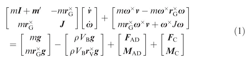
where v and ω are the airship flight velocity and angular rate.The first term in the left is the mass matrix,where the coupling elements of added mass in oblique diagonal lines are ignored;I stands for the identity matrix of 3X3;m and m′stand for the total mass and added mass matrix of airship;J stands for the moment of inertia matrix of airship including added inertia matrix;the second term in the left is the inertial force;the first term and the second term in the right are Gravity and buoyancy,where rGand rVare the radius vector of the center of gravity and center of volume,g the gravity acceleration;ρ and VBthe atmospheric density and airship volume;rV=0 while the body coordinates are based on the center of volume;FADand MADare aerodynamic forces and moments with not considering the additional mass;FCand MCare control force and moments.
The lateral equations of a rigid airship consist of 6 equations,such as the state equations of the lateral velocity/yaw/roll,the roll/yaw angular rate motion equations,and a side slip angle equation.
Airships shape are always symmetric in longitudinal profile,which means rG=[ax,0,az]Tand at the moment of inertia matrix J,Jxy=Jyz=0.axand azstand for the location of mass center in x and z axis,while Jxyand Jyzthe products of inertia on xOy and yOz plane.In addition,stratospheric airship is usually neutral buoyant,thus mg=ρVBg.Considering above,simplified equations for the lateral channels are as follows:14,15
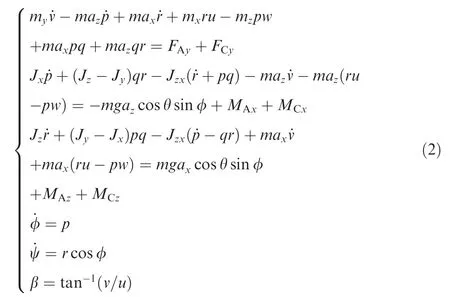
where mx,myand mzdenote airship mass including added mass on each axis;Jx,Jy,Jzand Jzxdenote elements of inertia matrix J;u,v,w and p,q,r denote items of linear speed flight velocity v and angular rate ω;φ,θ and ψ denote the Euler angle of airship motion;FAy,MAxand MAzdenote the elements of aerodynamics force FADand moment MADon each corresponding axis;FCy,MCxand MCzdenote the elements of control force FCand moment MCon each corresponding axis;β denotes the sideslip angle.
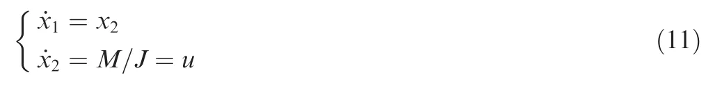
Roll control is always given up due to its inherent stable oscillation and the lack of effective control actuators.In addition,lateral speed is not the direct control objectives.Thus these equations can be removed from the dynamics equations.Dynamics equations are left with only a second-degree system composed by yaw channel and can be written to a simplified model as follows:

where
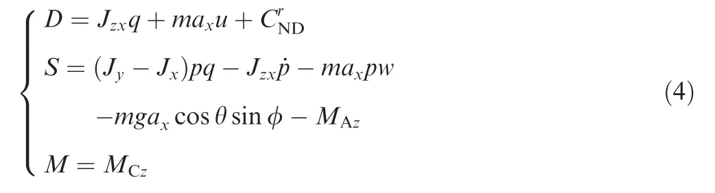
where J=Jzdenotes the airship inertia of z-axis moment(accounting additional inertia),D the damping associated with the yaw rate,S the disturbance for all other factors and M the yaw moment control.Besides,denotes the dynamic damping items generated by aerodynamics,which will be discussed in the following section as well as other details of the terms in Eq.(4).
2.2.Damping and disturbance
A brief analysis of yaw channel dynamics is given here to describe the characteristics of stratospheric airship yaw movement.In Eq.(4),both Jzxand q are small,while q is in the oscillatory mode,resulting a small effect on the damping.axis the relative position between the center of gravity and the center of volume,and this term describes the moment of inertia caused by the airship forward velocity,which is proportional to the forward velocity.is the dynamic damping generated by aerodynamic because of the yaw angular speed of airship.For a certain speed,usually16

where ρ∞and U∞denote air flow density and speed;Shandldenote airship characteristic area and length;denotes the coefficient of dynamic derivative which is a function of sideslip angle β.
That is,the dynamic derivativeis proportional to airspeed.In fact,even if airspeed is zero,the dynamic derivative still exists,which are not described in the existing model.Even an airship was rotating while staying at a permanent position,the dynamic derivative makes the airship reach a steady state of a constant angular velocity,preventing the unlimited growth of yaw speed.
All items are considered as disturbances in Eq.(4)except the control moment and the damping.Roll states(φ,p,˙p)are in oscillatory(subsidence)mode and typically disturbance.Steady state aerodynamic MAzis related to airspeed and side slip angle.In low speed situation,aerodynamic moment is very small thus MAzcould be treated as the disturbance.At a certain speed,yaw channel has a weakly unstable characteristic in a small sideslip angle,and becomes stable when sideslip angle increased Aerodynamic forces in this situation will lead to a yaw damping mode.
The brief analysis shows that in low-speed situation(e.g.,zero speed turning),the simplification is reasonable and effective.When the velocity increases,the disturbance will increase and become complicated under the impact of the aerodynamic forces,while the damping increases.
2.3.Phase plane trajectory

Ignoring disturbance,the phase plane trajectory equation can be achieved by Eq.(3).

where C denote a constant value determined by initial conditions.Asymptote of the phase plane trajectory is the ultimate angular rate airship when turning

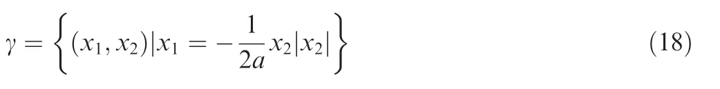
If M=0 N.m in Eq.(7),which means no control forces,the system will converge to the direction of r=0 rad/s.Phase trajectory at this time will be
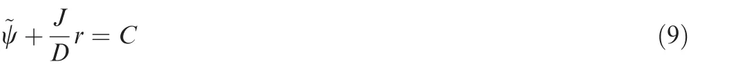
Fig.1 shows the phase trajectory of the airship yaw movement diagram.The vertical axis is the yaw rate,and the horizontal axis is the yaw angle error.If Mgt;0 N.m,the airship approaches to the asymptote along blue track,and eventually stabilizes at the extreme angular rate.Conversely,if Mlt;0 N.m,the airship approaches to the extreme angular rate along the green track.When control force disappears,the airship will be sliding slowly to the zero angular velocity point along the straight path.The final yaw angle is determined by the initial value.In fact,there are disturbances making the airship actual movement not strictly follow the curve,instead shaking right and left from the curves,but the basic law of motion is still valid.The dash line is the phase trajectory in the mathematical sense,but actually hard to occur,because the airship cannot exceed the limit angular rate theoretically.
The above phase trajectory analysis shows the change process of airship yaw movement.With sufficiently precise dynamics model,the phase trajectory can be used to control law design.However,Eq.(7)still has a complicated form of too much dependent variable.Meanwhile it is difficult to obtain the precise model of the aerodynamic forces,hence there are difficulties in practical application.If ignoring all damping term,that is D=0 N.m.s,it can be expected that the system is in a tough situation.Then the phase trajectory of the system is

Fig.1 Phase plane trajectory of yaw motion.

Fig.2 Phase plane trajectory of yaw motion when ignoring damping.

The phase trajectory becomes a parabola,as shown in Fig.2.Depending on the direction of external forces,airship angular rate continues to increase or decrease after the limit is reached,performing continued accelerate increase of yaw angle.The angular acceleration is constantly M/J,determined by control torques and inertias.In this case,the damping is ignored(mainly aerodynamic damping),which seems that the airship is moving in''vacuumquot;.
3.Controller design
3.1.Minimum time controller
According to the analysis above,when the damping is ignored,the yaw channel control becomes
It is a classic optimal control problem which could be solved by minimum theory on minimum time target for this system.

where the maximum control inputwith|M|maxthe maximum moment could be applied;t0and tfdenote the initial and finish time;~ψ0and r0denote the yaw error and yaw speed values at initial time.This is an optimal control problem of fixed terminal,free time and constrained control input.Let Hamiltonian:

where λ1and λ2denote Lagrange multiplier.According to the canonical equation,we have

where c0and c1are the coefficients to be determined.The transversality condition is

where the superscript*stands for optimal value under the optimal controller.Hence the optimal control is

The phase plane trajectory equation under the control becomes
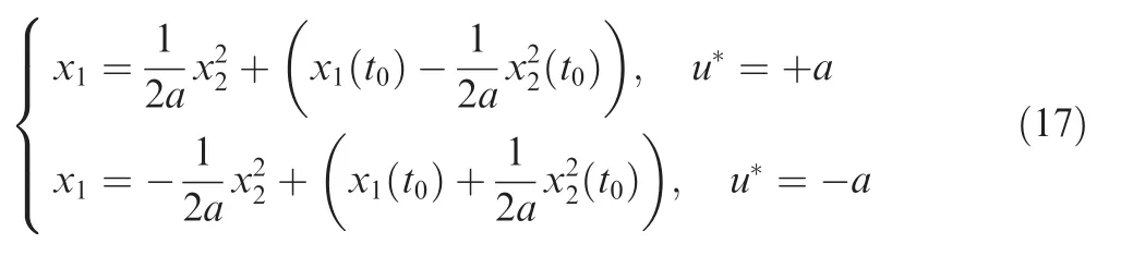
The above phase trajectories are all parabolas.The optimal trajectory satisfying terminal requirement is
As a result,a Bang–Bang controller will be gained as shown in Fig.3.When the initial phase point is in P0,firstly apply control according to u*=-a,until the phase trajectory moving and achieving the gamma curve at P1,apply control according to u*=+a,making the phase trajectory move to the origin point.The control logic becomes
When initial yaw angle rate is zero,which means x2(t0)=0,x1location corresponding to point P1can be calculated by the Eq.(17):The control strategy is equivalent to:applying the–|M|maxtorque control before the control error is reduced toand then applying|M|maxtorque control,which achieves the target with minimum time.
3.2.Phase plane controller

Fig.3 Phase plane trajectory with Bang–Bang controller.
When ignoring the damping,the airship yaw control can be solved by Bang–Bang controller based on optimal control theory.However,similar to the sliding mode controller,the existence of disturbance will result in a repeating switch of control output in the ideal track,as the dash arrow curve shown in Fig.3.The Trajectory will not smoothly slide along to origin point,but swing along the ideal curve because of the damping and control inputs.This will cause the decline of control effect and overburden of actuator.A dead zone can be employed here to solve this problem.
A simple control strategy is shown in Fig.4.Four phase trajectory curves divide the phase plane into three zones,with the control inputs becoming three discrete numerical conditions of u*=+a,-a and 0.When the system is in the zone I,airship is controlled to turn left at full speed.When the system is in the zone II,turn right at full speed.At the zone III,yaw control input is set to zero.This strategy assures that yaw angle error is limited within the zone III.The width of the dead zones is preset byandwherestands for demanded yaw angle error limits andis a designed angle rate which is less than the maximum yaw angle rate.Considering Fig.1,an idealshould be the intersection point of M=0 N.m curve(translation to passing origin point)and the control curve,which means while actuator shuts down,the airship will slide to the origin point itself.It's hard to find that value and accurate simulation will help.
The applied control algorithm will be
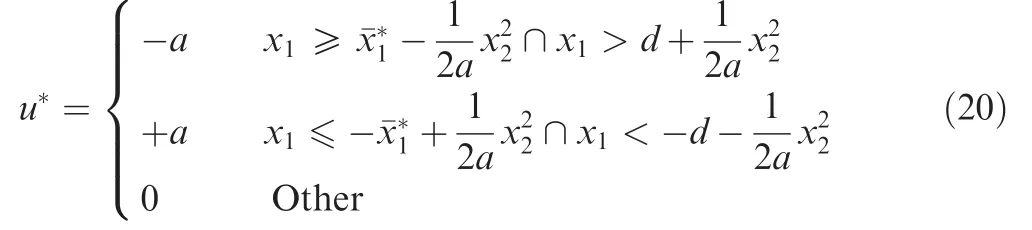
where

Furthermore,more control outputs could be added for better effects,not only a switch curve of u*=±a.For instance,while adding switch tracks of u*=±a/2,six parabolas can be used as switching line,divided the phase plane to five zones,as shown in Fig.5.
Zones III and IV are divided from dead zone in Fig.4.In zone III turn left at a half speed while in zone IV turn right at a half speed.Switching trackis employed instead of x2=0 to divide half speed zone from dead zone,for a reason measuring error of inertial measurement unit(IMU),where k denotes a designed coefficient of IMU measuring noise relevant toThe measuring error could induced by the measurement accuracy,the Earth rotation and location movement of IMU related to the airship,etc.The applied control algorithm will be shown in Fig.6.

Fig.4 A simple Bang–Bang controller with dead-zone.

Fig.5 A phase plane controller with five divided zones.
3.3.Further discussion
As motioned before,it is reasonable that if more output points are employed,the phase plane could be divided into more zones.This method may provide examples for such problems.
While yaw trajectory is located in dead zone,the control output is set to zero.Sometime other control algorithm such as PID could be employed in dead zone,for the error is limited in a small band.The PID controller will achieve a better control accuracy while control output changes small.
Back to the phase plane controller,a small number of parameters are needed for determination and each parameter has a clear physics meaning.It makes the method easy for usage and brings good application prospect.
4.Verification
4.1.Simulation
Taking the simulation stratospheric airship in Ref.11as example,the effectiveness of the above control law is demonstrated.The specification and control parameters are shown in Table 1.A vectored tail propeller is employed for yaw control,with maximum rotor speed of 1200 r/min corresponding to the maximum thrust of about 85 N under airspeed of 12 m/s at level flight height of 18.2 km.The maximum deflection angle is 60°.The wind speed is 18 m/s,direct from west to east.Initial heading angle of airship is 0°,while initial airspeed is 0 m/s.
Simulation focuses on the initial phase when airship climb to stratospheric height and starts to level flight.With a 1000 s for stabilizing,the yaw controller is acted with an expected yaw angle of 90°,while the actuators are activated.Control algorithm adopts the phase plane control of five divided zones in Fig.5.Fig.7 shows the curve of yaw angle and the movement of yaw actuator.It is seen that after about 120 s,the airship accesses to and stay in the error band of 5°.Yaw actuator motion is limited to only a finite value.Fig.7 shows phase trajectory change of the yaw angle tracking error.
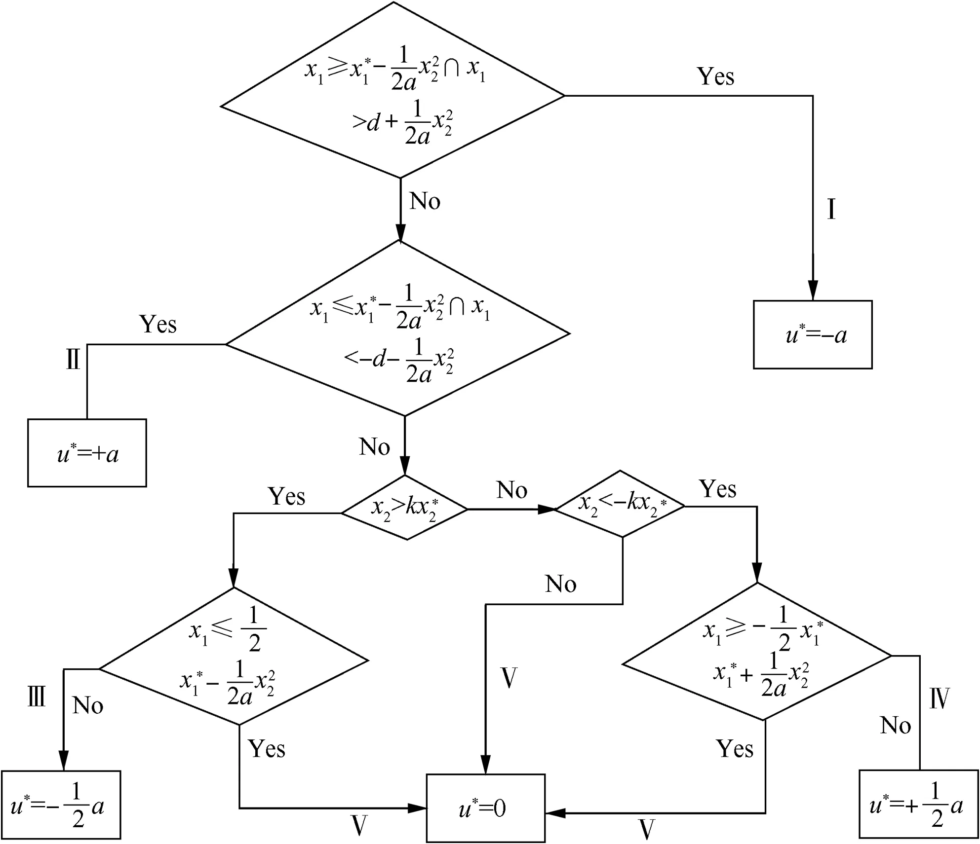
Fig.6 Applied control algorithm of five divided zones.
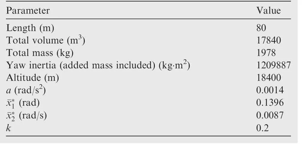
Table 1 Specification and control parameters of simulation airship.
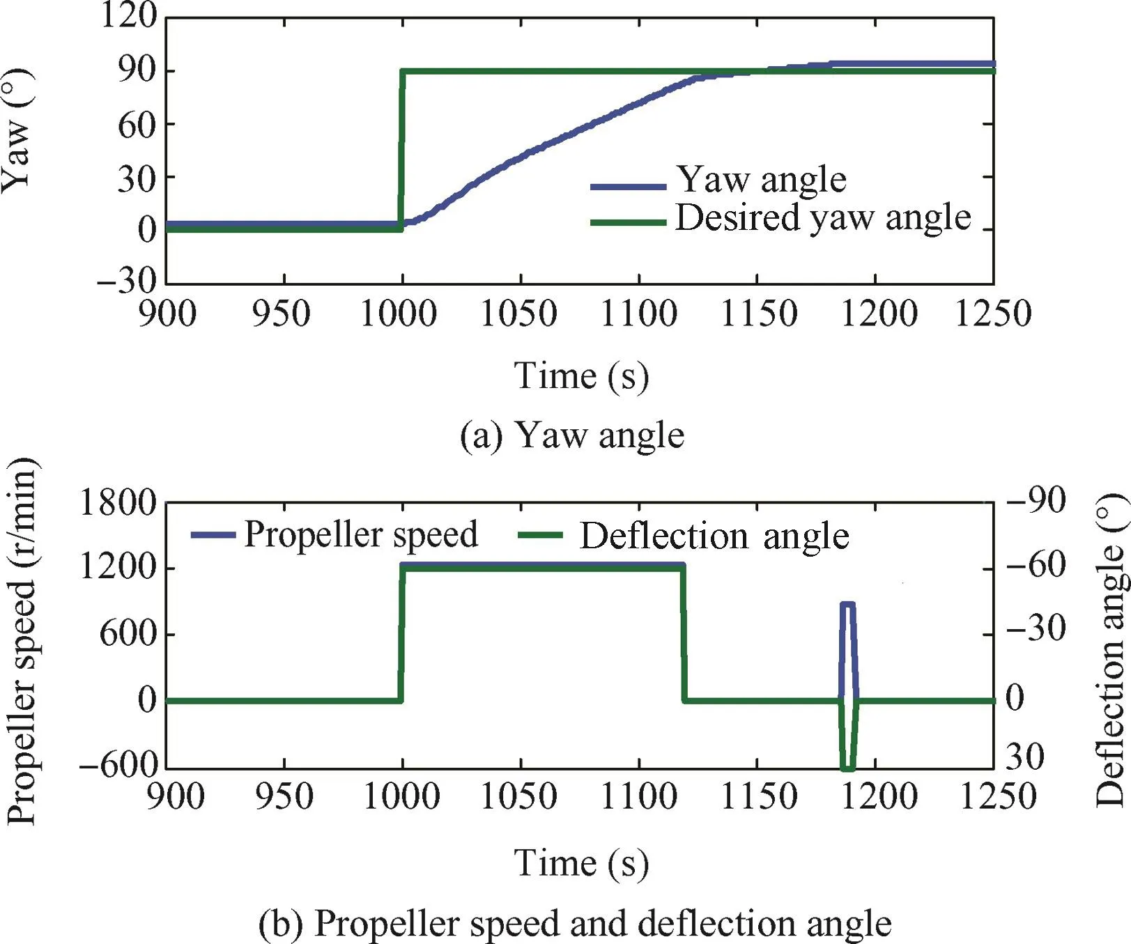
Fig.7 Simulation results of yaw controller and servo output.
For the convenience of description,only three zones are drawn in diagram.The initial yaw angle error is about 90°,thus the phase trajectory locates in the zone II in Fig.8,then the controller starts to work,guiding the phase trajectory to the dead zone.In the case of maximal yaw torque,the angular velocity in phase trajectory achieves maximal until achieving the switching track.While the trajectory moves into the dead zone,actuators are controlled to be zero,and the yaw angle error and yaw speed decrease slowly to zero because of the damping.The controller performs to achieve the anticipated goal.
4.2.Flight test
The performance of the controller is tested in a flight test of a verified stratospheric airship approximately the same as the simulation airship.When arriving at level flight altitude,the desired heading command is transmitted to the controller for making the airship heading aweather,and actuators are activated.The local wind direction is determined by airship floating trajectory without actuator.The main propellers are also not activated at this period.
Fig.9 shows the airship flight trajectory and yaw angle curve in control process.Controller is activated at the''Startquot;point,while the main propellers are not activated.At the''Finishquot;point,the initial yaw controller is finished and a wind direction estimation is activated to provide variable desired aweather command.Meanwhile the main propeller starts to work for thrust.A complicated control strategy is employed here,but it is beyond the scope of this article.
Fig.10 shows the rotor speed and deflection angle fed back by actuators.For protection of actuators,rotor acceleration and deflection angle rate are limited.Airship heading changes from initial 69.4°to steady 220°gradually as expected.The controller achieves a desired effect and the control process is relatively smooth,eventually the airship yaw angle error is limited in the range of 5°.Meanwhile deflection angle and rotational speed are successfully limited in a certain range.The controller is proved of effectiveness.

Fig.8 Phase plane trajectory motion in control proceeding.
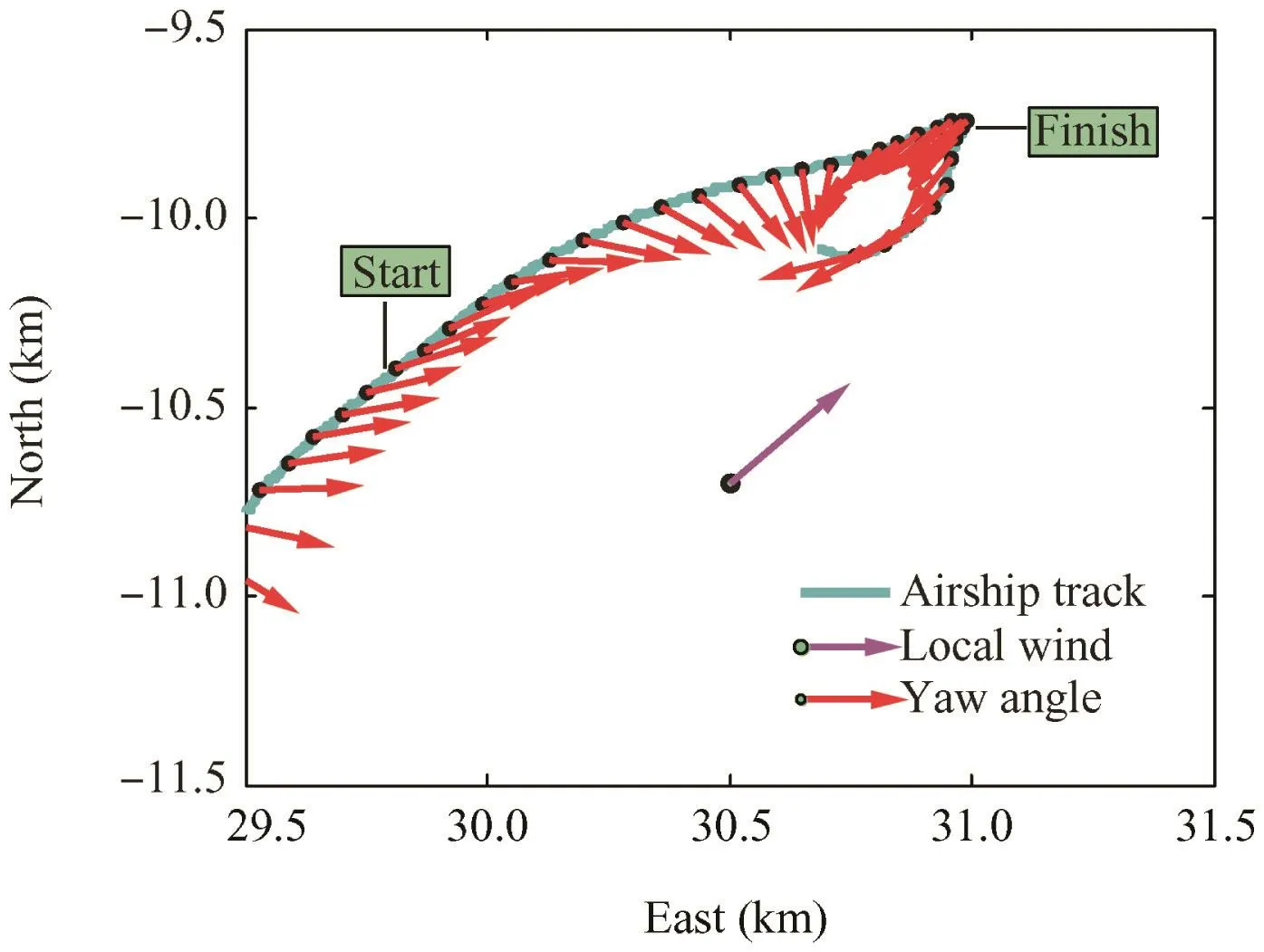
Fig.9 Trajectory and attitude of yaw control in flight test.

Fig.10 Yaw angle and servo outputs in flight test.
5.Conclusions
(1)Based on the movement characteristics of the stratospheric airship yaw attitude,the yaw channel dynamics is simplified into a second-order system.Items of yaw channel are all attributed to damping and disturbances.The dynamics of the yaw channel is analyzed and the results show that yaw motion tends to a maximum-angular-rate trajectory,but if not considering the damping,the trajectory becomes a simple parabola curve.
(2)The optimal time controller is designed using the minimum principle,with a typical form of Bang–Bang controller.Furthermore,a phase plane dead zone is set on the Bang–Bang controller's phase plane and a more complicated division is induced for the phase plane controller.
(3)Numerical simulation and flight tests are made to prove that the controller is reasonable and effective.Although this method will lose the control accuracy to a certain extent,it still provides a control algorithm with engineering practice and effectively eases the airship yaw actuator constraint in the current circumstances.
Acknowledgements
This article was sponsored by the National Defense Science and Technology Innovation Fund Projects of Chinese Academy of Science(No.CXJJ-14-M06).
1.Lee M,Smith S,Androulakakis S.The high altitude lighter than air airship efforts at the US army space and missile defense command/army forces strategic command.2009 May 4–7.Report No.:AIAA-2009-2852.
2.Androulakakis S,Judy R.Status and plans of high altitude airship(HAATM)program.2013 Mar 25–28.Report No.:AIAA-2013-1362.
3.Smith S,Fortenberry M,Lee M,Judy R.HiSentinel80:flight of a high altitude airship.2011 Sep 20–22.Report No.:AIAA-2011-6973.
4.Li ZB,Wu L,Zhang J,Li Y.Review of dynamic and control of stratospheric airships.Adv Mechan 2012;42(4):482–93 Chinese.
5.Kohno T,Sasa S.Control and guidance of low altitude stationary flight test vehicle.2005 Sep 26–28.Report No.:AIAA-2005-7406.
6.Fang CG,Wang W.Pitching attitude dynamics modeling and its control of unmanned dirigible airship.Control Theory Appl 2004;21(2):231–8 Chinese.
7.Lee SJ,Kim DM,Bang HC.Feedback linearization controller for semi station keeping of the unmanned airship.2005 Sep 26–28.Report No.:AIAA-2005-7343.
8.Yang YN,Wu J.Attitude control for a station-keeping airship using feedback linearization and fuzzy sliding mode control.IEEE Int J Innov Comput Inf Control 2012;8(12):8299–310.
9.Qu WD,Luo C,Ouyang J.Robust directional control of an unmanned airship.Acta Simulata Syst Sin 2004;16(11):2575–9 Chinese.
10.Azinheira J,Paiva E,Ramos J.Mission path following for an autonomous unmanned airship.Proceedings of IEEE international conference on robotics and automation;2000 Apr 24–28;San Francisco(CA).Piscataway(NJ):IEEE Press;2000.p.1269–75.
11.Miao JG,Wang F,Yang YC,Zhang XQ.Analyses and comparisons for several flight control configuration of stratospheric airship.Proceedings of 2014 IEEE aerospace conference;2014 Mar 6–13;Big Sky,Montana.Piscataway(NJ):IEEE Press;2014.
12.Han D,Wang XL,Chen L,Duan DP.Command-filtered backstepping control for a multi-vectored thrust stratospheric airship.Trans Inst Meas Control 2016;38(1):93–104.
13.Chen L,Zhou G,Yan XJ,Duan DP.Composite control strategy of stratospheric airships with moving masses.J Aircr 2012;49(3):794–801.
14.Yang YN,Wu J,Zheng W.Design,modeling and control for a stratospheric telecommunication platform.Acta Astronaut 2012;80(6):181–9.
15.Li YW,Nahon M.Modeling and simulation of airship dynamics.J Guid Control Dyn 2007;30(6):1691–701.
16.Jones SP,DeLaurier JD.Aerodynamic estimation techniques for aerostats and airships.J Aircr 1983;20(2):120–6.
Miao Jinggangis an engineer at the Academy of Opto-Electronics,Chinese Academy of Science(CAS)and a Ph.D.candidate from University of Chinese Academy of Science.His main research interests are dynamics modeling and flight control of light-than-air vehicle.
Zhou Jianghuais a researcher and Ph.D.supervisor at the Academy of Opto-Electronics,CAS.He received the Ph.D.degree form Xi'an Jiaotong University.His current research interest is dynamics and flight control of lighter-than-air vehicle.
Nie Yingis an engineer at the Academy of Opto-Electronics,CAS.His main research interest is airship propulsion technology.
Yang Xinis an expert enjoying the Special Government Allowances of the State Council and Ph.D.supervisor at the Academy of Opto-Electronics,CAS.His current research interests are spacecraft control and safety design for space systems.
1 September 2015;revised 3 December 2015;accepted 6 February 2016
Available online 9 May 2016
Attitude control;
Dynamics modeling;
Optimal control;
Phase plane method;
Stratospheric airship
Ⓒ2016 Chinese Society of Aeronautics and Astronautics.Production and hosting by Elsevier Ltd.This is an open access article under the CCBY-NC-ND license(http://creativecommons.org/licenses/by-nc-nd/4.0/).
*Corresponding author.Tel.:+86 10 82178835.
E-mail address:miaojg@aoe.ac.cn(J.Miao).
Peer review under responsibility of Editorial Committee of CJA.
杂志排行
CHINESE JOURNAL OF AERONAUTICS的其它文章
- Optimization on cooperative feed strategy for radial–axial ring rolling process of Inco718 alloy by RSM and FEM
- Measuring reliability under epistemic uncertainty:Review on non-probabilistic reliability metrics
- Optimum blade loading for a powered rotor in descent
- Experimental study of ice accretion effects on aerodynamic performance of an NACA 23012 airfoil
- Parachute dynamics and perturbation analysis of precision airdrop system
- Simulative technology for auxiliary fuel tank separation in a wind tunnel