Effect of blade tip winglet on the performance of a highly loaded transonic compressor rotor
2016-11-23HanShaobingZhongJingjun
Han Shaobing,Zhong Jingjun
Marine Engineering College,Dalian Maritime University,Dalian 116026,China
Effect of blade tip winglet on the performance of a highly loaded transonic compressor rotor
Han Shaobing*,Zhong Jingjun
Marine Engineering College,Dalian Maritime University,Dalian 116026,China
The tip leakage flow has an important influence on the performance of transonic compressor.Blade tip winglet has been proved to be an effective method to control the tip leakage flow in compressor,while the physical mechanisms of blade tip winglet have been poorly understood.A numerical study for a highly loaded transonic compressor rotor has been conducted to understand the effect of varying the location of blade tip winglet on the performance of the rotor.Two kinds of tip winglet were designed and investigated.The effects of blade tip winglet on the compressor overall performance,stability and tip flow structure were presented and discussed.It is found that the interaction of the tip winglet with the flow in the tip region is different when the winglet is located at suction-side or pressure-side of the blade tip.Results indicate that the suction-side winglet(SW)is ineffective to improve the performance of compressor rotor.In addition,a significant stall range extension equivalent to 33.74%with a very small penalty in efficiency can be obtained by the pressure-side winglet(PW).An attempt has been made to explain the fundamental mechanisms of blade tip winglet in detail.
1.Introduction
The tip leakage flow has a detrimental impact on the efficiency,pressure rise and stability of axial compressors.1There are two aspects of the tip leakage flow;one is blockage and the other one is aerodynamic loss.2–4Complicated tip flow structuresare generated by the tip leakage flow and its interactions with the passage shock wave,the casing boundary layer and the blade wake in transonic compressor rotors,which are often considered as the reasons of rotating instability.The investigation of tip leakage flow in axial transonic compressor rotors has received an increasing interest in the published reference,and some basic understanding has been revealed.Suder and Celestina5have shown that the passage shock wave/tip leakage vortex interaction plays a major role in generating endwall blockage of a highly loaded transonic axial compressor rotor.Chima6has carried out a numerical study on the interaction of tip leakage vortex,the passage shock wave and the endwall boundary layer.Yamada et al.7considered tip leakage vortex breakdown as a possible cause of stall inception in axial transonic compressor rotors.
A variety of active and passive flow control methods have been studied to control tip leakage flow in axial compressor.Bae8investigated the use of three types of fluidic actuators to control the tip clearance flows in a linear cascade.They found that directed synthetic jet and steady directed jet can eliminate tip clearance-related blockage effectively.Suder et al.9reported on the application of discrete tip injection to a high-speed axial compressor to enhance compressor stability.They achieved a 6%reduction in stalling flow coefficient when injecting 2%of the annulus flow at design speed.Lu et al.10investigated the fundamental mechanisms of axial skewed slot casing treatment and their influences on the subsonic axial flow compressor rotor flow field.Legras et al.11studied numerically the influence of circumferential casing grooves on the tip leakage flow and its resulting vortical structures.Hah and Shin12investigated the detailed flow behavior in a modern transonic fan with a compound sweep.Compound sweep was found to be an effective means of controlling the tip flow structures.
It has been recognized that the use of special blade tip geometries can be effective in reducing tip leakage flow.Lu et al.13conducted a computational study on the function of blade tip cutting in axial flow compressors,concluding that the blade tip cutting technique was rather case dependent and the performance of the cut blade is very sensitive to the shape of blade leading edge.Zhang et al.14performed an experimental investigation on the effects of suction side squealer tip on the performance of a low-speed axial compressor.Ma et al.15conducted an experimental investigation of grooved tip clearance effects on the flow field of a compressor cascade.Zhong et al.16studied the effects of blade tip winglets on the aerodynamic performance of a linear compressor cascade.Results indicate that the use of proper tip winglets in a compressor cascade can positively affect the tip flow field by weakening the tip leakage vortex.
However,the use of blade tip winglets has never been investigated in transonic compressor rotors so far.In this paper,the effect of blade tip winglet on the performance of a highly loaded transonic compressor rotor has been investigated with the help of NUMECA software.The purpose of this investigation aims at advancing the understanding of fundamental mechanisms of blade tip winglet in transonic compressor rotors.
2.Compressor model
2.1.Investigated compressor rotor
The axial compressor rotor,NASA rotor 37,was used in the present numerical investigation.As reported by Yamada7,stall inception phenomena will occur in the blade tip region for this rotor caused by tip leakage vortex breakdown when the tip leakage vortex interacts with the passage shock wave at near stall condition.The detailed parameters of the rotor are summarized in Table 1.The meridional plane of the axial compressor rotor is shown in Fig.1.17As Fig.1 shows,total pressure and total temperature were measured at two axial stations located upstream of the rotor blade leading edge(Station 1)and downstream of the rotor blade trailing edge(Station 4)near the hub,respectively.18

Table 1 Design parameters of rotor 37.

Fig.1 Locations measured in experiment of rotor 37.17
2.2.Blade tip winglet design
Fig.2 shows the schematics of the different blade tip winglet designs.A blade tip winglet is installed on the suction or pressure side of the blade in the tip region.The blade winglet is arranged along the suction or pressure side tip edge line from the blade leading edge to the blade trailing edge and has a varying width.The blade tip winglet profiles were generated by translating the blade tip profiles away from the corresponding suction and pressure surfaces.19The winglet profiles were slightly modified in their leading and trailing regions to maintain a constant leading edge and trailing edge thickness.The contour of the tip winglet/blade junction was smoothed to avoid any discontinuities on the blade surface so that a low increase of the local stresses concentration would be expected.20With this rotor tip modification,the tip winglet and rotor blade were designed as one part.The winglet width or extent away from the original blade surface is equal to 2 times of the local blade tip thickness.So the suction-side winglet(SW)case will be referred to as SW2.0 case,while the pressure-side winglet(PW)case will be called PW2.0 case and the baseline tip without winglet case will be called NW case in this paper.
3.Numerical calculation method
3.1.Numerical model

Fig.2 Design of rotor blade tip winglet.
The commercial solver NUMECA/EURANUS was used for the simulation.The flow is modeled using the Favre–Reynoldsaveraged N-S equations,which are discretized using a cell-centered explicit finite volume scheme.The integration in time is implemented through the four-step explicit Runge–Kutta integration algorithm.The one-equation turbulence model from Spalart–Allmaras was applied to model the turbulence viscosity.In addition,implicit residual smoothing and multigrid method were used in the simulation.All calculations were run with a Courant–Friedrichs–Lewy(CFL)number of 3.
3.2.Computational grid

Fig.3 Computational grid.
Fig.3 shows the computational grid used in the present work.The main flow region was meshed with a block structured topology consisting of 6 H-blocks and 1 O-block around the blade(see Fig.3(a)).73 cells were used to model the blade passage in the span wise direction.For the blade-to blade direction,41 cells were used.The O-type grid of blade has 129 cells in the circumferential direction to ensure a high-quality mesh at the leading and trailing edge.The O-type and H-type grids embedded in the tip clearance region had 17 cells in the span wise direction.The whole grid system had 620,585 cells.The minimum grid spacing on the solid wall was 3X10⁻⁶m to evaluate the viscous fluxes at the wall.This minimum grid spacing renders y+≤5 at the walls to make the near wall mesh meet the requirement of the Spalart–Allmaras model in NUMECA.The same mesh was used for all calculations with and without blade tip winglet.A grid independency study was conducted by coarsening and refining the grid,and results show that the solution became grid independent at the present grid density.
3.3.Boundary conditions
Boundary conditions were specified as follows.At the inlet,total pressure,total temperature and flow angle were specified.At the outlet,the hub static pressure was specified and simple radial equilibrium was solved.At the walls,no-slip and adiabatic wall conditions were used.In order to save computational time,a single passage,steady analysis was carried out by applying periodic boundary condition both with and without blade tip winglet.All numerical simulations were started at the choke point and then marched towards the near stall point with gradual increase in outlet static pressure.In order to capture the near stall condition accurately,the increase of the outlet static pressure was reduced to the lowest level.The near stall condition was obtained to be the last stable operating condition before the numerical divergence.Chima,6Legras11and Beheshti et al.21have carried out satisfactory steady simulations covering the entire rotor 37 characteristics up to near stall conditions.
4.Validity of simulation
For the validation of the present numerical solutions,Fig.4 shows the comparison of computational and experimental distribution of total pressure ratio and is entropic efficiency with respect to mass flow rate.In the figure,the experimental and computed mass flows were normalized by their respective choking flow rates.The calculated total pressure ratio has a good agreement with the experimental data.However,the simulation gives a little lower stall point as compared to experimental results(Fig.4(a)).As shown in Fig.4(b),the calculated adiabatic efficiency is lower than the experimental data;this observation is similar with the results from Legras11and Zhang.22The reason for this is that the experimental data was obtained in a manner that neglected the high loss regions of the compressor rotor in the annulus boundary layers,as discussed by Denton.23However,the shape of the efficiency curve is well predicted on the whole.Computed and measured contours of relative Mach number contours at 95%span at points near peak efficiency and near stall are compared in Fig.5.As shown in Fig.5(a),a shock wave standing ahead of the leading edge that runs obliquely downward to the suction side of the neighboring blade is well captured for the near peak efficiency condition.At near stall condition,a quite good agreement between the calculated and measured shock/leakage vortex interaction and a large region of low-momentum fluid follows downstream can be observed in Fig.5(b).

Fig.4 Comparison of calculated and experimental rotor characteristics at design speed.
5.Results and discussion
5.1.Overall characteristics
Rotor characteristics of both baseline tip and winglet tip configurations obtained at design speed by simulation are compared in Fig.6.For each rotor,the mass flow is normalized using the corresponding computed choking mass flow rate.The comparison of the three compressors performances indicates that implementation of suction-side winglet induces a lower stall margin and a small penalty in compressor efficiency.With suction-side winglet,the peak efficiency of the rotor is reduced by about 0.47%.On the contrary,the pressure-side winglet greatly improves the stall margin and introduces only a very small penalty in efficiency.At peak efficiency point,there is an efficiency reduction of about 0.27%.

Fig.5 Comparisons of relative Mach number contours at 95%span of rotor 37.
The predicted penalty in rotor is entropic efficiency is due to the additional surface offered by tip winglet which increases the additional skin friction loss.Moreover,the pressure-side winglet causes a slightly higher pressure ratio near the stall point relative to the reference case.In order to evaluate the improvement in stall margin by tip winglet in the present work,the calculation of the stall range extended(SRE)follows the definition suggested by Hathaway24in the equation below:

where mchokerepresents the mass flow rate at the choke point,mstallthe mass flow rate at the stall point.
By applying pressure-side winglet,the stall range predicted by the present work is extended by 33.74%.This shows a significant improvement in the stall range of the compressor rotor.The application of suction-side winglet,instead,provides a stall operating range reduction of 9.29%with respect to the baseline blade.
5.2.Flow mechanism for the rotor at the point close to stall
In order to elucidate the physics that underpin the different flow behavior shown in Fig.6,the flow feature should be compared under the same reference condition.In the present study,for the case with pressure-side winglet,this is ensured by comparing the final predicted flow field at the baseline rotor near stall flow rate,corresponding to the 91.6%normalized mass flow point approximately.For the case with suction-side winglet,the near stall condition corresponds to the 92.3%normalized mass flow point.

Fig.6 Effects of tip winglet on compressor rotor maps.
In Fig.7 the low energy regions(tip blockage)are shown by a pink isosurface of relative Ma=0.2.As shown in Fig.7(a),for the baseline tip case,the most dominant flow feature within the passage is that a local low-speed region can be seen near the leading edge of the pressure surface,covering wide range of the tip region.This region is thought to cause blockage of flow field area,which may lead to instabilities like compressor rotor stall.For the case with suction-side winglet,the lowmomentum flow region expands both radially and tangentially,which leads to an increase in the tip flow blockage.It explains why the suction-side winglet does not succeed to extend operability of the rotor.For the case with pressure-side winglet,the size of the predicted low-energy zone has been considerably reduced.This effect is obviously shown in Fig.7(c).
In Fig.8,the relative Mach number at 98%of span is illustrated for the baseline rotor and is compared to the rotors with tip winglet.The tip leakage vortex path upstream of the shock wave can be inferred from the deflections of the relative Mach contour and is shown by a broken line.It can be seen that there is a low momentum fluid region adjacent to the blade pressure side which is believed to be caused by the shock wave/tip leakage vortex interaction.This region alters the main flow field,which plays a dominant role in stall inception of the rotor.For the case with suction-side winglet,the shock stands farther ahead of the blade than the baseline tip case and intersects the suction surface further upstream.As a consequence,the passage shock and tip leakage vortex meet closer to upstream of the blade passage and a larger region of lowvelocity fluid follows downstream.However,it can be seen that the separation region at the suction surface near the trailing edge is reduced for the suction-side winglet tip case.As shown in Fig.8(c),in contrast to the case with suction-side winglet,the blocked flow region near the blade leading edge is largely reduced by the pressure-side winglet.Reduction of the large pockets of low-momentum fluid near the tip of the blade can contribute to a reduction of the tip leakage flow intensity and can therefore improve the compressor rotor stability.Moreover,the trajectory of the tip leakage vortex is changed by the tip winglet.The suction-side winglet gives a steeper angle for the tip leakage trajectory.
Fluid particles of the tip leakage vortex for the cases with and without tip winglet are compared in Fig.9.In this figure,the leakage streamlines are colored with the magnitude of relative velocity(Wxyz).Fig.10 shows the contours of normalized vorticity in several selected planes near normal to the rotor tip chord direction.The normalized vorticity ξnis de fined as follows:

where ξ and ω are the vector of the absolute vorticity and magnitude of the rotor angular velocity.From these figures,it is apparent that the behavior of tip leakage flow shows a distinctive change by applying tip winglet.For the baseline tip case,the leakage vortex originates near the blade leading edge,migrates toward downstream pressure side of the adjacent blade and impacts on the blade pressure surface before reaching the blade trailing edge.As seen on the planes upstream of the shock,the tip leakage vortex has a concentrated vorticity before interacting with the passage shock.However,the tip leakage vortex expands both radially and tangentially after it passes through the shock.In addition,as the vortex expands,the region with a highly concentrated vorticity expands abruptly,and the velocity in the vortex core region is so low that it decreases almost to zero.These feathers indicate that a tip vortex breakdown has been caused by the interaction of the leakage vortex and the passage shock,as shown by Yamada et al.7Needless to say,the large spread of the lowmomentum fluid region due to the vortex break down means a sudden growth of endwall blockage effect,as shown in Figs.7(a)and 8(a).In the condition with the suction-side winglet applied,the shock wave/tip leakage vortex interaction is being intensified which leads to a stronger change in the tip leakage vortex structure.It is found that the tip leakage twists seriously and a spiral type breakdown seems to occur at the middle of the rotor passage.In the case with pressure-side winglet,the tip leakage vortex trajectory is more inclined in the streamwise direction.In addition,the distance from the first tip leakage vortex appearance at the suction surface to the intersection with the shock is longer than the corresponding distance in baseline tip case.With the longer distance,the low momentum core fluid is reenergized as tip leakage vortex mixing with main flow,as discussed by Kablitz et al.25for a swept transonic compressor rotor.Therefore,a relative weak interaction between shock wave and tip leakage vortex occurs.Hence,the blockage generated by the shock wave/tip leakage vortex interaction is alleviated,which results in an increase in stable operating range of the compressor rotor.Besides,remarkable changes can be observed that the tip leakage vortex core corresponds to lower values of vorticity than the reference case.This implies the reduction of tip leakage flow intensity due to the effects of pressure-side winglet.

Fig.7 Isosurface of relative Mach number Ma=0.2.

Fig.8 Distribution of relative Mach number at 98%span.
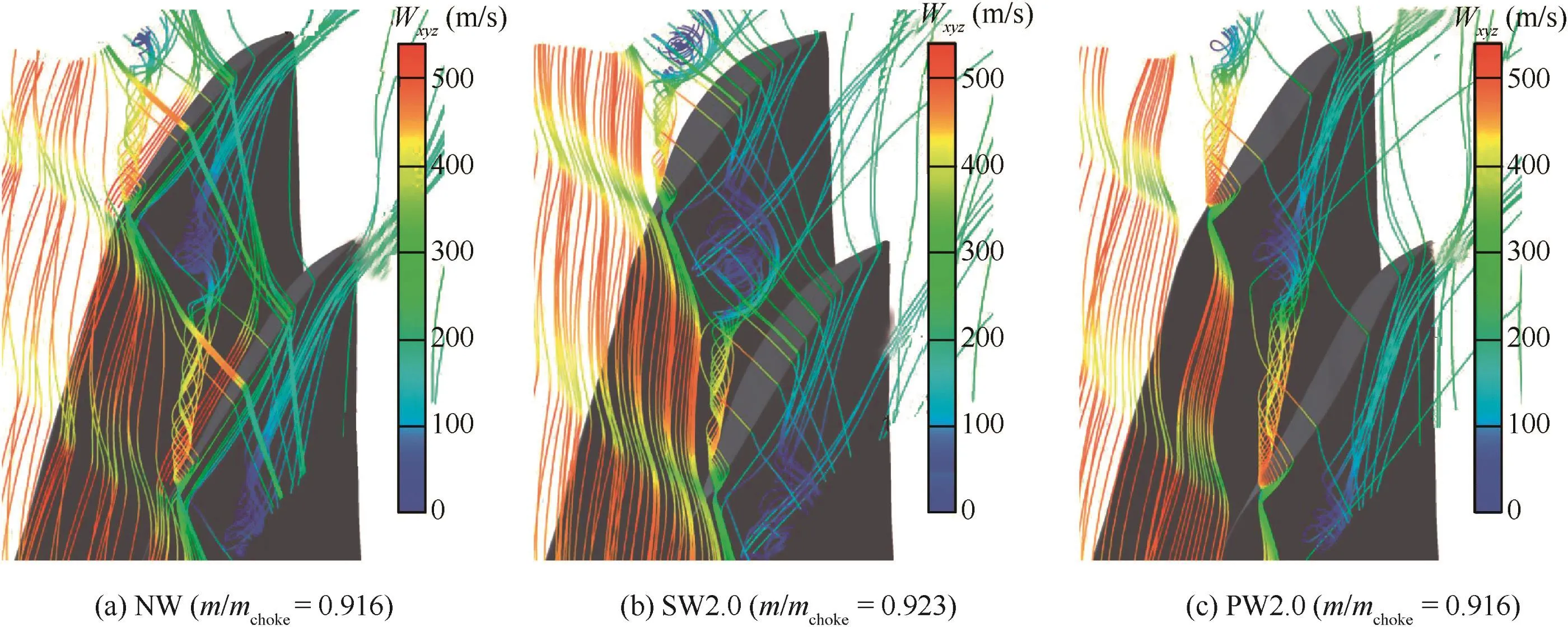
Fig.9 Leakage streamlines released in blade tip region.

Fig.10 Normalized vorticity distributions on crossflow planes.

Fig.11 Entropy distributions on crossflow planes.
Fig.11 shows the entropy distribution at several crossflow planes.The incoming main flow/tip leakage flow interface associated with high entropy gradient,visible as a dashed red line that separates the incoming and tip leakage flows,lies at the leading edge plane.The computations carried out by Vo et al.26show that when the solution limit is reached the incoming main flow/tip leakage flow interface is aligned with the rotor leading-edge plane at the blade tip and verified by Hah et al.27in a transonic compressor rotor.It can be seen that the interface for suction-side winglet case is located closer to the leading edge slightly than that for baseline case.Moreover,the entropy field shows that the high losses influenced by the tip leakage vortex are higher and the high loss region is larger than the baseline tip case.The high loss region corresponds to the blockage region due to the accumulation of the low-energy fluid.In contrast to that,entropy values for pressure-side winglet case are visibly lower in the tip leakage vortex region and azimuthal extension of the high loss area is smaller,which indicate that the flow with the pressure-side winglet case is more stable than the other cases.Consequently,the compressor rotor can be able to operate in even further throttled operation conditions.
The influence of tip winglet on the performance of the compressor rotor can be better understood by determining the blade loading variation due to winglet.The static pressure coefficient distribution along the blade at 98%span is compared between baseline tip case and the winglet cases in Fig.12.The blade tip winglets extend the blade tip into the passage,which change the throat area of the blade and thus alter the loading of the blade.The blade loading distributions for the baseline case and pressure-side winglet case look similar except for the region near the leading edge.The pressure-side winglet induces increases in static pressure coefficient on the first 7%of the pressure surface,indicating an increase in loading.The increase of the load at the tip of the pressure side strengthens the capacity of increasing pressure ratio.For the suction-side winglet case,the distribution of static pressure on the suction surface indicates that the passage shock position moves further upstream,which coincides with relative Mach number contour shown in Fig.8(b).It can also be seen from Fig.12 that blade loading near the leading edge and the passage shock location is reduced by the suction-side winglet.This implies that the suction-side winglet reduces the work done by the compressor rotor in contrast to other blade tip cases.

Fig.12 Static pressure coefficient distribution at 98%span.
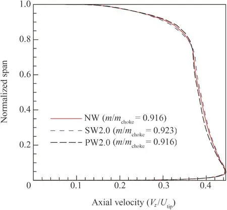
Fig.13 Spanwise distribution of axial velocity at Station 3.
The span wise distribution of axial velocity at Station 3 is shown in Fig.13,Vzdenotes the axial velocity,Utipthe peripheral speed of blade at tip.As illustrated,the suction-side winglet tip increases the blockage near the casing,thus the axial velocity is reduced near the casing.The pressure-side winglet weakens the tip leakage flow and relieves the shock wave/tip leakage vortex interaction.Therefore the blockage near the casing is reduced.Consequently,the axial velocity is increased near the casing region but is decreased in the main core flow region due to the mass flow continuity.
6.Conclusions
The current work presents a numerical simulation for a state of the art design of blade tip winglet.A transonic axial compressor rotor,NASA rotor 37,has been studied with and without blade tip winglet in order to explore the effects of blade tip winglet on the compressor performance and its flow mechanism for stall margin improvement.The conclusions are drawn as follows:
(1)The suction-side winglet is found to be ineffective to improve the performance of compressor rotor.It induces 9.29%lower stall margin and also causes 0.47%peak efficiency reduction in comparison with the baseline tip case.
(2)The pressure-side winglet is effective to increase the rotor stall margin with a very small penalty in efficiency over the whole operating range.It achieves 33.74%stall rang extension compared to the baseline tip and shows 0.27%efficiency reduction under the peak efficiency condition.
(3)For the baseline tip case,the low-momentum flow region induced by shock wave/tip leakage vortex interaction is a primary factor for the rotor instability.The suctionside winglet intensifies shock-vortex interaction,which leads to an increase in the tip flow blockage.
(4)The pressure-side winglet weakens the tip leakage flow and alleviates the shock wave/tip leakage vortex interaction,thus the blocked flow region near the tip is reduced,which results in noticeable improvement in stall margin.
In conclusion,the effectiveness of blade tip winglet depends on the winglet location configuration.A transonic compressor rotor with pressure-side winglet has been already manufactured,which will be tested in the near future.
Acknowledgments
This research was co-supported by the National Natural Science Foundation of China(Nos.51436002,51406021),the Scientific Research Fund of Education Department of Liaoning Province(No.L2014197),the Program for Liaoning Innovative Research Team in University(No.LT2015004),and the Fundamental Research Funds for the Central Universities(Nos.3132016014,3132014319).
1.Wisler DC.Aerodynamic effects of tip clearance,shrouds,leakage flow,casing treatment and trenching in compressor design.Von Karman Institute Lecture Series;1985.p.1–90.
2.Bae J,Breuer KS,Tan CS.Control of tip clearance flow in axial compressor.AIAA fluids 2000 conferenceamp;exhibt;2000 June 19–22;Denver,Colorado,USA.Reston:AIAA;2000.p.1–9.
3.Khalid SA,Khalsa AS,Waitz IA,Tan CS,Greiter EM,Cumpsty NA,et al.Endwall blockage in axial compressors.J Turbomach 1999;121(3):499–509.
4.Storer JA,Cumpsty NA.An approximate analysis and prediction method for tip clearance loss in axial compressors.J Turbomach 1994;116(4):648–56.
5.Suder KL,Celestina ML.Experimental and computational investigation of the tip clearance flow in a transonic axial compressor rotor.J Turbomach 1996;118(2):218–29.
6.Chima RV.Calculation of tip clearance effects in a transonic compressor rotor.J Turbomach 1998;120(1):131–40.
7.Yamada K,Furukawa M,Inoue M,Funazaki KI.Numerical Analysis of tip leakage flow field in a transonic compressor rotor.Proceedings of the international gas turbine congress;2003 Nov 2–7;Tokyo,Japan.2003.p.1–8.
8.Bae J.Active control of tip clearance flow in axial compressors[dissertation].Boston:Massachusetts Institute of Technology;2001.
9.Suder KL,Hathaway MD,Thorp SA,Strazisar AJ,Bright MB.Compressor stability enhancement using discrete tip injection.J Turbomach 2001;123(1):14–23.
10.Lu X,Chu W,Zhu J,Zhang Y.Numerical investigation of the coupled flow through a subsonic compressor rotor and axial skewed slot.J Turbomach 2008;131(1),011001–8.
11.Legras G,Gourdain N,Trebinjac I.Numerical analysis of the tip leakage flow in a transonic axial compressor with circumferential casing treatment.J Therm Sci 2010;19(3):198–205.
12.Hah C,Shin HW.Study of near-stall flow behavior in a modern transonic fan with compound sweep.J Fluids Eng 2012;134(7):3412–27.
13.Lu J,Chu W,Zhang H.Influence of blade tip cutting on axial compressor aerodynamic performance.Proc Inst Mech Eng Part G 2009;223(1):19–29.
14.Zhang J,Ma H,Li J.Effects of suction side squealer tip on the performance of a low-speed axial compressor.J Therm Sci 2012;21(3):223–9.
15.Ma H,Zhang J,Zhang J,Zhou Y.Experimental study of effects of grooved tip clearances on the flow field in a compressor cascade passage.J Turbomach 2012;134(5):597–626.
16.Zhong J,Han S,Lu H,Kan X.Effect of tip geometry and tip clearance on aerodynamic performance of a linear compressor cascade.Chin J Aeronaut 2013;26(3):583–93.
17.Suder KL.Experimental investigation of the flow field in a transonic,axial flow compressor with respect to the development of blockage and loss.[dissertation].Cleveland:Case Western Reserve University;1996.
18.Hah C.Large eddy simulation of transonic flow field in NASA rotor 37.Arlington,VA:National Aeronautics and Space Administration(US);2009.Report No.:NASA/TM-2009-215627.
19.Schabowski Z,Hodson H.The reduction of over tip leakage loss in unshrouded axial turbines using winglets and squealers.J Turbomach 2014;136(4):663–75.
20.Moritz KK,Bohn D,Sugimoto T,Tanaka R.Reduction of tip clearance losses in an axial turbine by shaped design of the blade tip region.Proceedings of ASME turbo expo 2007:power for land,sea and air;2007 May 14–17;Montreal,Canada.2007.p.541–51.
21.Beheshti BH,Teixeira JA,Ivey PC.Parametric study of tip clearance-casing treatment on performance and stability of a transonic axial compressor.J Turbomach 2004;126(4):527–35.
22.Zhang Y,Lu X,Chu W,Zhu J.Numerical investigation of the unsteady tip leakage flow and rotating stall inception in a transonic compressor.J Therm Sci 2010;19(4):310–7.
23.Denton JD.Lessons from rotor 37.J Therm Sci 1997;6(1):1–13.
24.Hathaway MD.Self-recirculating casing treatment concept for enhanced compressor performance.ASME turbo expo 2002:power for land,sea and air;2002 June 3–6;Amsterdam,The Netherlands.2002.p.411–20.
25.Kablitz S,Passrucker H,Hennecke DK,Engber M.Experimental analysis of the influence of sweep on tip leakage vortex structure of an axial transonic compressor stage.Proceedings of 16th international symposium on air-breathing engines;2003 Aug 31–Sep 5;Cleveland,Ohio,USA.2003.p.1–7.
26.Vo HD,Tan CS,Gretizer EM.Criteria for spike initiated rotating stall.ASME turbo expo 2005:power for land,sea and air;2005 June 6–9,Reno-Tahoe,Nevada,USA.2005.p.155–65.
27.Hah C,Bergner J,Schiffer HP.Short length rotating stall inception in a transonic axial compressor-criteria and mechanismas.ASME turbo expo 2006:power for land,sea and air;2006 May 8–11;Barchlona,Spain.2006.p.61–70.
Han Shaobingreceived the B.S.,M.S.and Ph.D.degrees in marine engineering from Dalian Maritime University in 2007,2009 and 2013 respectively,and then became a teacher there.His main research interest lies in the area of turbomachinery aerodynamic.
Zhong Jingjunis a professor and Ph.D.supervisor at College of Marine Engineering,Dalian Maritime University.His received the Ph.D.degree from Harbin Institute of Technology in 1996.He current research interest lies in the area of turbomachinery aerodynamic.
2 June 2015;revised 13 October 2015;accepted 15 January 2016
Available online 10 May 2016
Blade tip winglet;
Numerical study;
Shock wave/tip leakage vortex interaction;
Stall range;
Transonic compressor rotor
Ⓒ2016 Chinese Society of Aeronautics and Astronautics.Production and hosting by Elsevier Ltd.This is an open access article under the CCBY-NC-ND license(http://creativecommons.org/licenses/by-nc-nd/4.0/).
*Corresponding author.Tel.:+86 411 84725039.
E-mail address:hanshaobing@126.com(S.Han).
Peer review under responsibility of Editorial Committee of CJA.
杂志排行

CHINESE JOURNAL OF AERONAUTICS的其它文章
- Optimization on cooperative feed strategy for radial–axial ring rolling process of Inco718 alloy by RSM and FEM
- Measuring reliability under epistemic uncertainty:Review on non-probabilistic reliability metrics
- Optimum blade loading for a powered rotor in descent
- Experimental study of ice accretion effects on aerodynamic performance of an NACA 23012 airfoil
- Parachute dynamics and perturbation analysis of precision airdrop system
- Simulative technology for auxiliary fuel tank separation in a wind tunnel