Design of Two-wheeled Mobile Control Robot with Holographic Projection
2016-10-22LIMingyang
LI Ming-yang
(Beijing Institute of Technology, Beijing 100081, China)
Design of Two-wheeled Mobile Control Robot with Holographic Projection
LI Ming-yang
(Beijing Institute of Technology, Beijing 100081, China)
In this paper, we design a two-wheeled mobile robot which could be control by Android mobile phone. The way that controlling robot through Android software is easy and convenient for people to use; while the two-wheeled mobile robot owns the characteristics of adaptation and flexibility. As a platform, this robot can accomplish a series of functions by combining it with different additional modules. Therefore, this robot has significant spreading value and promising application future. As for the principle of controlling the robot: by adjusting the direction of rotation of two isolating electric motor, we can keep its balance. By changing the dip of the robot, in other words, changing the speed of rotation of electric motor, we can determine the speed of the robot. Through controlling the difference of the speed between two electric motors, we can adjust the direction of the robot. All controlling depends on the feedback provided by optical encoder, gyroscope and accelerometer. As for human-computer interaction, we accomplish human-computer communication on the basis of Bluetooth, and we design an Android software used for direct the robot. Through experiment, we confirmed that the robot can keep balance itself, and can be controlled to move in a specific direction by our Android software. In the end, through establishing small-scale holographic projection equipment on the robot, we discuss the prospect of it.
Mobile control robot; Android; Human-computer interaction; Holographic projection
0 INTRODUCTION
With the development of technology,robotics technology plays an increasingly important role in people’s life and production. Robot integrates machinery,computers,electronics,physics,control,artificial intelligence and other aspects of technology,which is an integrated application platform. Wheeled robot is an important ramification of robotics branch,which has several superiorities such as stable operation,high energy efficiency,institutional simple structure,environmental adaptability,etc.,and has broad application prospects. Two-wheeled self-balancing robot belongs to a kind of wheeled robot,and its structure is:coaxial two-wheeled,two independently driven. Through modulating and regulating the motor output of the robot body to maintain homeostasis,and implement walking upright and steering as well as other movements. Compared with the traditional three-wheeled and four-wheeled wheeled robots,two-wheeled self-balancing robot has the following outstanding advantages:First:flexible operation and agile movement,and can be achieved in situ steering; Second:small footprint,and can walks in narrow space; Third:simple robot structure,and easy to control.
The current mainstream way to use men-machine interaction widely depends on graphical user interface or multimedia user interface. Compared against the traditional command interface,it is more intuitionistic to use. However,this type of interaction is still using a keyboard,mouse,and this type of interaction is still using a keyboard,mouse,and other conventional input devices,which is inefficient and lacks of flexibility. The ideal interactive system is supposed to have highly friendly user interface,and universal portability. And based on a platform of Android phones,using software development toimplement the men-machine interaction with mobile phone interface,we can well achieve the goal. Besides,Android development based on java language,so providing a general application programming interface,the development can be simple and short-period. Currently on the market and Internet,various applications which are based on Android platform emerge in endlessly,so that people feel the pleasure and convenience of the electronic age. The market prospects are very bright and in all aspects of work and life.
According to the above analysis,we designed and produced a prototype of a phone-based control of two-wheeled robot. We combined this platform with holographic projection technology,and conducted a preliminary exploration in the application prospects of this platform. Namely through the application of two-wheeled robot phone software control and displaying its three-dimensional image,we research and study the possibility of using two-wheeled robot to achieve dynamical real object representation in the future.
This article is organized as follows:First,we present the overall design of two-wheeled robot. Second,we present further specific and detail design of robot system in hardware and software systems,which in turn through a combination of robotics and three-dimensional image display to research the prospect. At last,we present an actual inspection of the overall system’s work with a summary and an outlook.
1 OVERALL DESIGN OF ROBOT
1.1Demand analysis:
According to the design purpose,we summarize that the robot is supposed to have the following features and functions:
1. The robot is a kind of two-wheeled robot.
2. When the robot is relatively static,it can stand evenly.
3. When the robot is in the state of motion,it can achieve to go forward,go backward,turn left,turn right and other actions.
4. Robot depends on Android phone software to control the motion,namely control the state of static and mode of movement.
5. Robots can be used as platform to achieve independent function as mounted modules.
1.2Overall design:
To achieve the targets,in the mechanical structure,we take the wheel coaxial structure for mechanism to serve as the robot’s support. When we set up the system,at the same time,we make the center of gravity as low as possible.
In the electronic system,we use XS128 single chip microcomputer to serve as the control center of the robot system to process information of each subsystem and to coordinate their work.
In the motor drive,we choose BTN7970 for two motors to drive the wheels turn.
In the motion control,we take optical encoder,and use an acceleration sensor and a gyroscope to serve as a sensor for determining the motion state of the robot and to provide for the microcontroller Decision parameters basis.
In men-machine interaction,we use Android mobile phone software to serve as an interactive interface and we make man-machine communication via HC-06 Bluetooth module to convey instructionsto the robot.
In accordance with the design and instruction mentioned above,we figure out the robot system diagram as follows(Fig.1):
2 DESIGN OF EACH SYSTEM IN THE ROBOT
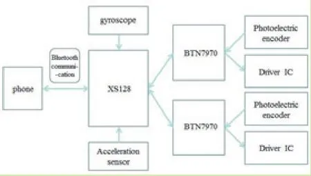
Fig.1 Schematic diagram of the system
2.1Power system
The power supply system offer voltage 7.2V.
And the power supply directly offers to the motor and steering engine. At the same time we apply highpower voltage regulator to power the microcontroller and other sensors.
2.1.1SCM power regulator module
Since the mainboard of XS128 microcontrollers and other modules are supposed to be supplied with 5V voltage,so in order to ensure the proper operation of the microcontroller and other modules,we need voltage regulator module to reduce the voltage.
We use LM2596 chip to power microcontroller. LM2596 series is a 3A output current step-down switching regulator integrated chip,which contains a fixed frequency oscillator (150KHZ)and the reference voltage regulator (1.23v),and have perfect protection circuit,current limiting,thermal shutdown circuit,etc. The schematic of power supply shows below(Fig.2).
2.1.2Gyroscopes and accelerometers power
regulator module
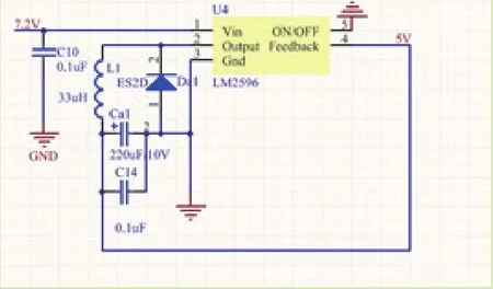
Fig.2 Schematic diagram of circuit
To ensure supplying the accelerometer and gyroscope with 5V regulator power,we apply the module LM2940 (maximum operating current of 1A,low dropout three-terminal regulator which can output stable voltage) to achieve the conversion from 7.2V to 5V. Operating schematic is as follows(Fig.3).
2.2Driving system
We use a dedicated chip BTN7970 as motor driver chip. The four BTN7970 were barricaded two H-bridge to control the left and right motor and output PWM wave,enabling the robot two wheels to be separately controlled. Such method of driving has several advantages such as high current,convenienceof operation,good stability. The system circuit is as follows(Fig.4).

Fig.3 Schematic diagram of circuit
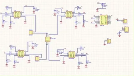
Fig.4 Schematic diagram of circuit
2.3Robot motion control system
The maintenance of the robot standing upright and motion comes from two wheels; meanwhile the wheel is powered by two DC motors. Therefore,from the view of control,as an object to be controlled,the robot’s control inputs are two motor speeds.
Control the movement of the robot can be summarized as follows:
Robot balance:to maintain the balance for the robot to stand upright by controlling the two motors’forward and inverse turning.
Control robot movement speed:by adjusting the inclination of the robot to achieve speed control that is by controlling the motor speed to achieve the wheel speed control.
Control robot movement direction:through control the differential between two motors’ rotation speed to achieve robot’s swerve control.
In the actual control process,the signals which control the state of the robot’s motion are superposed together to input into the motors. Therefore,as long as the motors operate in the linear state,we can control both balance and direction of the robot.
2.3.1The balance control
The robot balance control is achieved through a negative feedback mechanism.
As the robots can tilt only taking place on the wheel scrolling direction,it is easy for us to control wheel rotation to offset the trend (in one dimension) which may skew the robot’s balance to ensure the robot standing upright.
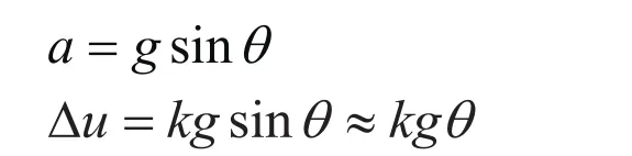
2.3.2Accelerometer
The acceleration sensor can measure the acceleration produced by the Earth’s gravitation or the movement of objects. Its small size and light weight are suitable for placement on a small,two-wheeled robot.
To calculate the inclination of the robot,it is only needed to measure acceleration in one direction. This design selected the acceleration signal which on its Z axis (vertical axis) direction. When the robot stands upright,Z-axis direction is vertical,and then the output signal of the acceleration sensor is zerobias voltage. When the robot is tilted,it will form a gravitational acceleration component in the Z-axis direction,which leads to an acceleration sensor output voltage change.
In fact,due to the acceleration in the Z-axis direction generated by the robot swing itself,the acceleration sensor causes a relatively great interference signal,so that the robot cannot obtain exact information of inclination. In order to obtain the information about tilt,it is also needed using the angular velocity sensor,which is a gyroscope.
2.3.3Angular velocity sensor (gyroscope)
Gyroscope can be used to measure rotation angle of the object. Since the object in the rotating coordinate system will be subject to the principle of the Coriolis force,the piezoelectric ceramic can be made into vibration component. When the component rotates,the angular velocity of the object can be measured which is response for the change of the vibrational frequency. We then can integrate the acceleration signal,so that the robot’s current inclination can be figured out(Fig.5).
Since the gyro’s output signal represents robot’s angular velocity,which is not affected by body movement,so that the signal noise is small. But the angle required integral calculation obtained by the angular velocity,so if there is a slight deviation or drift in the determination of the angular velocity,it can result in an accumulated error after integral calculation,leading to circuit saturation. Then it needs to correct the acceleration sensor angle information. By comparing the angle which is integrated and the angle which is obtained from gravitational acceleration,and using the deviation between them to regulate the gyro output,we make the angle which is integrated trace into the angle which is obtained from acceleration sensor in successive steps. To avoid or resolve oscillation phenomenon may occur,it needs to be applied a differential controller,which modulates PID item to control the robot in the program. Implementation is shown as follows(Fig.6).
In actual control,Z axis -T tracking curve is shown as follows(Fig.7).
Accelerometer and gyroscope circuit diagram is shown as follows(Fig.8).
2.3.4Robot speed control:
Robot speed control is achieved by controlling the inclination of the robot.
The robot’s wheel rotational velocity can be measured by the optical encoder which is mounted in the motor output shaft.
Circuit diagram is as follows(Fig.9).
By controlling the microcontroller,and statistical measurement of external counter,within a fixed time interval,the number of speed pulse signal can reflect the motor speed. By controlling the angle of inclination of a given value to control the robot,we can acquire a closed loop (negative feedback Fig.10).
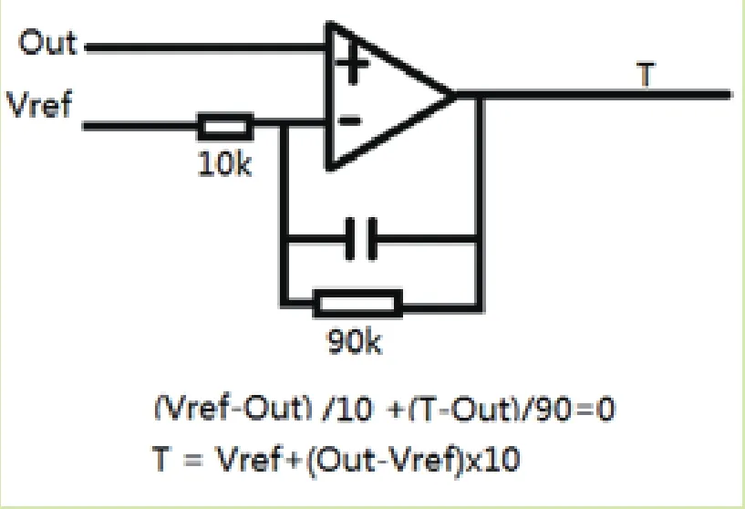
Fig.5 Feedback circuit
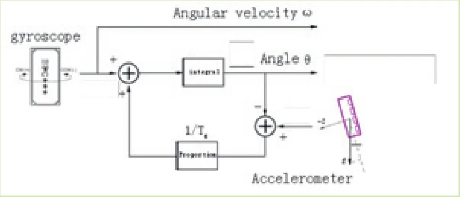
Fig.6 System of gyroscope
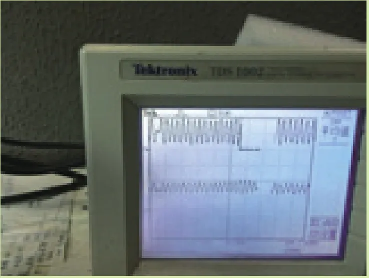
Fig.7 Signal ficture
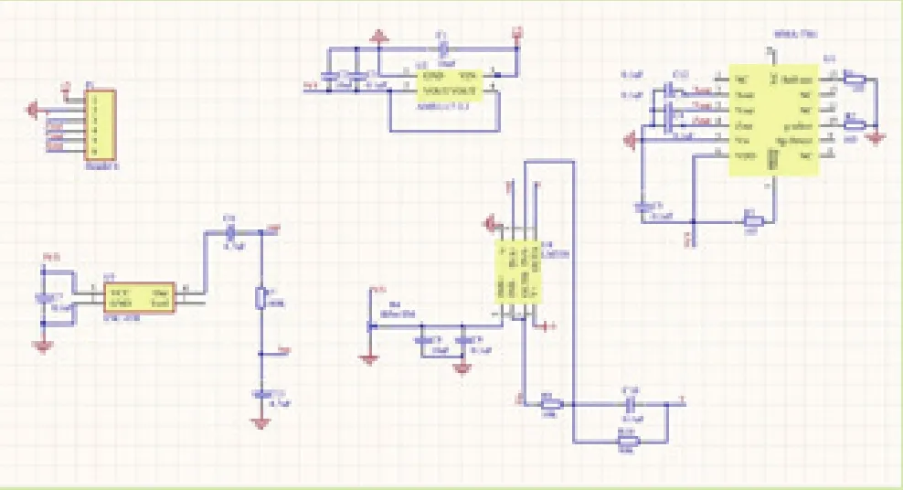
Fig.8 Accelerometer and gyroscope circuit diagram
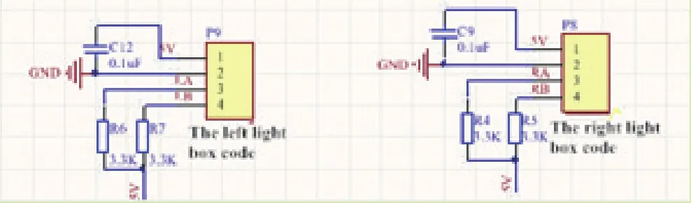
Fig.9 Circuit diagram
Inclination of the robot is generated by the motion of the wheel,so it can be figured out thatthe wheel speed is equal to the derivative of the angle variable and multiplied by robot’s length. Since there is a short transitional phase in the very beginning control,the robot has a relatively small angle,which causes the wheel speed changed little. Then you can ignore the wheel acceleration caused by the robot inclination.
The transfer functions of this process are:
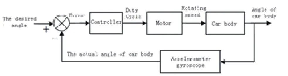
Fig.10 Negative feedback
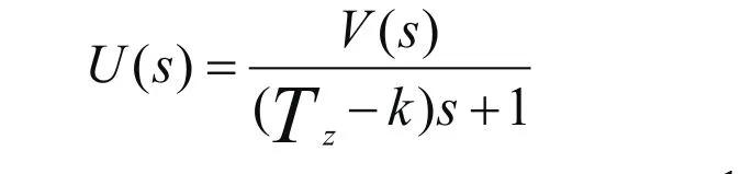
Therefore,to ensure the stability of the system,we have to meet that the robot angle adjustment time constant Tz is large,slow smooth speed adjustment,at the same time the speed of the feedback proportional k is small.
To achieve above control process and requirements,you can change the control cycle in programming,reduced control parameters for signal smoothing filter,etc.
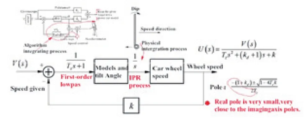
Fig.11 Control mode
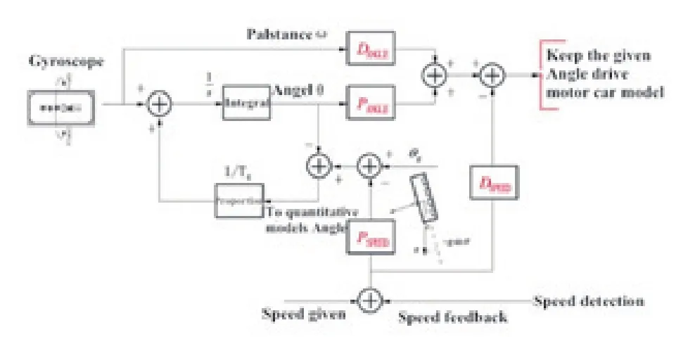
Fig.12 Improved control mode

Fig.13 The sketch map
2.3.5Stability of the robot velocity:
Movement speed of the robot is decided by the acceleration which is generated by the inclination. Integrating the inclination can determine the motion speed of the robot, The control mode is shown in Fig.11.
Since in the original system,the time constant of inclination adjustment process is often very large,it can be approximated as an integral part. By combining the differential part and the integral part to form a link and a part of a proportional control,we can maintain the control system transfer function stable.
Improved control mode is shown as follows(Fig.12).
From the above chart we can see that:the two control parameters determine the angle,which are the proportional control parameter P(ANGEL) and differential control parameter D(ANGEL). Speed control also depends on two parameters,called P(SPEED) and D(SPEED). Using differential control,it can increase the stability of the angle and speed of the robot,preventing control overshoot. On this basis,and then added to the speed error integral control,wecan set the amount of inclination of the robot,and integral compensation directly control the output of the angle of achieving PID control program(Fig.13).
2.4Phone control system based on Bluetooth communication and Android
With the rise of Internet of Things technology,Android mobile phone with its unique advantages,offers more quality and convenient technical achievement for us. In the two-wheeled robot interactive design,basing on mobile platform and using Bluetooth technology,we design and implement a twowheeled robot to achieve new solutions for men-machine interaction. Basing on mobile phone as control platform via Bluetooth communication to control motion of the robot to complete moving forward,moving backward,left front turn,right front turn,left back turn,right back turn,and other activities. 2.4.1 Bluetooth Module Introduction:
(1)Bluetooth technology components
Bluetooth technology consists of three parts:Bluetooth wireless technology,the Bluetooth protocol stack and Bluetooth interoperability. Bluetooth radio in universal 2.4GHz ISM (industrial,scientific,medical) band,supports full-duplex transmission,using IEEE 802.15 protocol. Bluetooth device plonks and plays,and has anti-interference ability,which is easy to use. Bluetooth protocol stack contains a software stack and a hardware stack. Bluetooth hardware protocol stack is provided by the Bluetooth hardware. Bluetooth software protocol stack is provided by the Bluetooth software. Bluetooth software stack provides Java Bluetooth API to the programmer that it is open to use. Bluetooth interoperability includes three aspects:First,Generic Access Profile defines the device management functionality;secondly,Service Discovery Application Profiles define the content of the service discovery; Third,serial Profiles define the interoperability of equipment and simulation of serial the ability of the cable.
(2)Bluetooth Module HC-06 Introduction:
Adopt CSR mainstream Bluetooth chip,Bluetooth V2.0 protocol standards. Core serial module operating voltage is 3.3V and the one with bottom plate can be between 3.1-6.5V. Baud rate is 1200,2400,4800,9600,19200,38400,57600,and 115200 that can be set by user.
Core Module size is:28mm * 15mm * 2.35mm. Plate size is 27mm * 47mm.
Working current:during matching is 50MA,after matching to communicate is 28MA.
Resting current:no rest.
It can be used with a Bluetooth laptop,computer plus Bluetooth adapter,PDA and other devices seamlessly connect.
Factory default parameters:Slave,baud rate:9600,N,8,1. Passcode:1234.
Bluetooth module internal reference diagram is as follows(Fig.14).
2.4.2Design of phone control software and procedures:

Fig.14 Bluetooth module internal reference diagram
Mobile interactive software designed using the Eclipse development environment. Eclipse is an open-source,java-based extensible development platform. In use,we also need to develop program J2ME’s EclipseMe,ADT and other plug-ins for Eclipse installation. Meanwhile,in order tofacilitate on a computer simulation to develop programs,we also need to install the Wireless Development Tools WKT,so we do not always have to download the program to execute after the installation on the phone to see the effect.
Software design diagram is shown in Fig.15:
1. Get Bluetooth devices.
2. Find available Bluetooth devices around,and get the MAC address to connect.
3. Set listener events,and sent data to the car control. In order to facilitate the operation, we set forward,backward and stop commands handled as follows:When the listener is clicked at one time,the robot continues the implementation. We set left and right turn instruction handled as follows:only the listener gets persistent pressed,the robot will be performed,and when the hand release the robot stops.
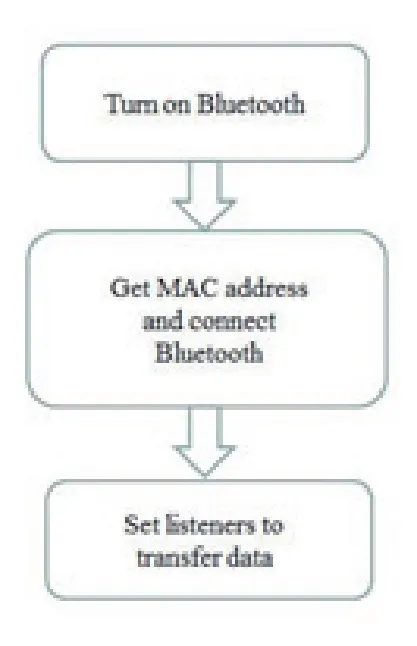
Fig.15 Software design diagram
3 PROSPECT OF 3D HOLOGRAPHIC PROJECTION TECHNOLOGY AND ITS APPLICATION
3.1Holography and holographic projection
Holography,namely all the information referring to the light,is different from the ordinary photography. Ordinary photography can record light intensity distribution,that is the amplitude information,but cannot record the phase information,and therefore there is no three-dimensional imaging. Holography interference of light can be used to record all the information of optical amplitude and phase,and then use diffraction reducing the amplitude and phase distribution of light to form a true three-dimensional image.
3.1.1Wavefront recording
Wavefront recording applies the light interference principle. Two beams of coherent light,after interference,form interference intensity distribution on the plane,including the amplitude and phase information.
Let object wave and reference wave can be expressed as:
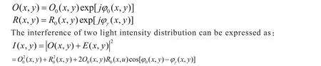
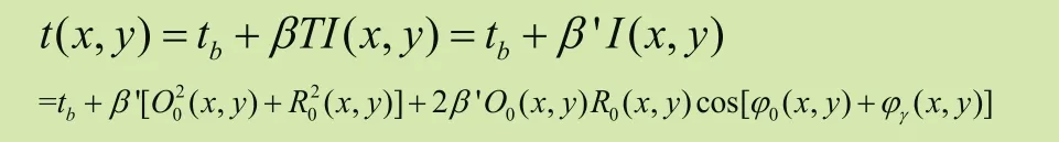
If the reference wave amplitude and phase information is known,the interference intensity distribution can be considered a record of object wave amplitude and phase information. Let the object wave and the reference light expose on the bottom edge,the film after development becomes a hologram recording object wave information. Holograms are formed by the bands,of which the positions of the bands record the object wave phase information,the degree of contrast record amplitude information.
In essence,the hologram is a complex grating,which complex amplitude transmission coefficientis:
3.1.2Wavefront reproducibility
Use a beam of coherent light wave:

to irradiate the hologram. Since the hologram is essentially a grating,and therefore the incident light diffraction phenomenon occurred. As a consequence,amplitude and phase of the incident light is modulated.
According to the theory of diffraction,diffraction waves through the hologram plane can be expressed as:

If so,then the third item of diffraction becomes the representation of the original object light wave. In other words,if the use of reference light to expose the hologram,the diffracted light can reproduce the wavefront of the object light wave,resulting in a virtual image of the original object.
Other components of diffraction waves are noise components. Restored virtual image is true threedimensional image.
3.1.3360degree holographic projection imaging
(1)Holographic projection technology(Fig.16):
Holographic projection technology is based on the principle of holography using the principle of interference and diffraction to record and reproduce objects in real three-dimensional image technology.
360degree holographic projection system is a real imaging system with a three-dimensional picture which is suspended in mid-air in the cabinet. 360 degree holographic projection system consists of the cabinet,spectroscope,spotlights,video playback equipment. It is based on imaging principle spectroscope,shot by real objects,and build three-dimensional models. Then the object images or three-dimensional model of the recorded image is superimposed into the scene constituting a display system combining static and dynamic.
Four video transmitters transmit the optical signal to the cone in a special prism. After the lights converge together,three-dimensional images with realistic dimensions of space are formed. Refracted and reflected by the surface of the mirror,the audience saw a cone of images and graphics from the three-dimensional space.
(2)Realization of 360 degree holographic projection imaging realization:
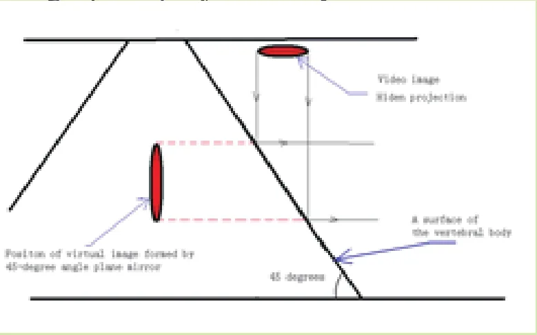
Fig.16 The sketch map of holographic projection
According to a 360-degree holographic projection imaging principle,on a substrate with a hard high-permeable membrane,we establish a regular pyramid organization,as an imaging mechanism. We play a particular video image via mobile phones. Video images included to show the front,the back and the two sides of the object in order to achieve the four video transmitters' function. By placement on asubstrate such as a stent fixation device,we make the phone fixed in place,so that the video image of the four parts can be separately projected into the four sides of the right square pyramid. When playing a video,it was observed with a three-dimensional dynamic image in the cone(Fig.17).
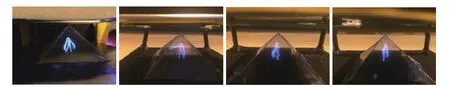
Fig.17 Effect picture
3.1.4Outlook based on application of two-wheeled robot platform:
According to 360-degree holographic projection imaging characteristics,it is suitable for display in kind of inconvenience exhibited objects (such valuable exhibition thereof),or small-scale demonstration of dynamic processes. Two-wheeled robot control via mobile phone shows the process can be adapted to a more complex environment. In addition,viewers also can,according to their needs and maintaining their positions unchanged,adjust the viewing angle and viewing distance. The entire device utilizes the advantages of two-wheeled small robot’s flexibility and the convenience of mobile phones and threedimensional holographic projection display. And this technology has high promotional value.
Admittedly,it is just an exploration and trial to achieve holographic projection applications on the two-wheeled robot platform. Using the advantages of two-wheeled robot and phone controller,we can also develop more rich applications.
3.2Implementation and Experiment
3.2.1Implementation and experimental of each module:
In accordance with the robot’s design part of the content,after planning,production,assembling circuit,we get every robot module(Fig.18):

Fig.18 Pictures of real products
3.2.2Implementation and experimental of overall robotic system:
Through the various subsystems and the robot’s body to be assembled,the driver program is written into SCM. We tested the balance of the robot when it stands upright in with power on. We use the phone to control the robot moving forward,moving backward,turning left,and turning right to achieve dynamic processes of holographic projection on the robot platform.
Therefore we successfully achieved the work that the two-wheeled robot with holographic projection can be controlled through Android mobile phone to move following the orders and it can project the holographic image. The results are in line with expectations(Fig.19).
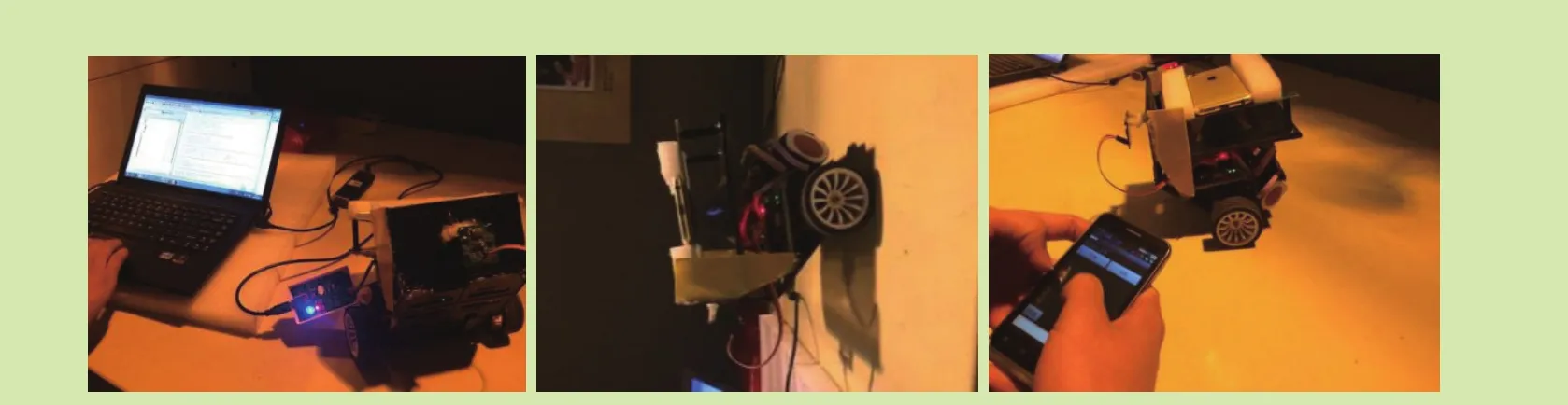
Fig.19 Result map
4 EPILOGUE
By integrating gyroscope accelerometer,Android software development,Bluetooth communication technology,and other aspects,we implemented a two-wheeled robot control by mobile phone. Robot itself has compact structure,flexible movement,and is easy to control. Android-based mobile phone software control system,simpler and convenient,consistent with the current people’s natural behavior. Therefore,the entire robotic system is a broad prospect of development platform. On this platform,through three-dimensional image by holographic projection technology show,we discussed the future with its prospects for (dynamic) object reproduction. We believe the future,this control is simple,flexible operation of the robot can carry more value,into millions of households.
[1] LIU Jin-kun. Intelligent control [M].Beijing:Electronic Industry Press 2005:21-22.
[2] MEI Xiao-rong. Automatic control components and circuit [M].Harbin:Harbin Institute of Technology Press 2004:16-17.
[3] LIU Jun-hua. Modern testing technology and test system design [M].Xi’an:Xi’an Jiaotong University Press 2000:19-20.
[4] GuihuaEr. Motion Control Systems [M].Beijing:Tsinghua University Press 2004:5-7.
[5] XU Guo-bao,YIN Yi-xin,ZHOU Mei-juan. Situation and Prospects intelligent mobile robot technology [J]. Robotics and Applications 2007(3):29-34
[6] XIE Tao,XU Jian-feng,ZHANG Yong-xue,QIANG Wen-yi. History humanoid robot research:Present Situation and Prospects [J]robots 2002(4):367-374
[7] DING Xue-gong. Robot Control [M]. Hangzhou:Zhejiang University Press 2006
[8] SUN Geng-xin. JAVAME Mobile Application Development Index [M].Beijing:Science Press 2008:272-278
[9] MA Jian-cang,LUO Ya-jun,ZHAO Yu-ting. Bluetooth Core Technology and Applications[M].Beijing:Science Press ,2003.
[10] JIN Chun,XU Guang-chen,SUN Rui.Bluetooth technology [M].Beijing:Electronic Industry Press ,2001.
[11] Bluctooth Specification Group. Core Specification V2.0+EDR,Specification ofthe Bluetooth System,2004.
[12] SUN Ge. Short-range wireless communications and networking technology [M]. Xi'an:Xi'an University of Electronic Science and Technology Press 2008:4.
[13] GAO Feng. Wireless City:carrier-grade Wi-Fi network construction and operation [M].Beijing:People Post Press 2011:10-11.
[14] HE Yong. Wireless LAN Solutions [J]Modern electronic technology,2007,22:93-95.
[15] XIAO Yang,Frank,LI Hai-zhon,LI Ming,LI Bo.Dynamic bandwidth partition schemes forintegratedvoice,video,and data traffic in the IEEE 802.11e distributed wirelessLANs[J].International journal of communication systems,2010,23(3):123-126.83
[16] Howitt I. WLAN and WPAN coexistence in ULband. Transactions on VehicularTechnology,2001,50(4):1114-1124.
[17] CAULFIELD H J,LU S.The application of holography[M]. New York:Wiely,1970.
[18] BRADLEY D D,POON T C. Gaussian beam analysis of optical scanning holography[J].J Opt Soc Am A,1992,9(2):229-236.
[19] QIL,WANGQH,LUOJY,etal. An Autostereoscopic 3D Projection Display Based on a Lenticular Sheet and a Parallax Barrier [J]. Journal of Display Technology,2012,8(7):397-400
[20] Guofeng Tong,Zizhang Wu,NinglongWeng,etal.An Omni-directional vSLAM based on Spherical Camera Model and 3D Modeling#M[J]. The Journal of New Industrialization,2012,2(2):8-17.
[21] WU Jin,WANG Jie. Android terminal common security issues and workarounds Analysis [J]. The Journal of New Industrialization,2015,5(5):55-61.
10.19335/j.cnki.2095-6649.2016.08.008
LI Ming-yang. Design of Two-wheeled Mobile Control Robot with Holographic Projection[J]. The Journal of New Industrialization,2016,6(8): 54-64.
李明阳(1993-),男,北京理工大学,光电信息工程
本文引用格式:LI Ming-yang. Design of Two-wheeled Mobile Control Robot with Holographic Projection[J]. 新型工业化,2016,6(8):54-64.
