A study of hybrid prediction method for ship parametric rolling*
2016-10-18YaohuaZHOU周耀华NingMA马宁JiangLU鲁江MinGU顾民
Yao-hua ZHOU (周耀华), Ning MA (马宁), Jiang LU (鲁江), Min GU (顾民)
1. School of Naval Architect, Ocean and Civil Engineering, Shanghai Jiao Tong University, Shanghai 200240,China
2. Shanghai Rules and Research Institute, China Classification Society, Shanghai 200135, China,E-mail:yhzhou@ccs.org.cn
3. State Key Laboratory of Ocean Engineering, Shanghai Jiao Tong University, Shanghai 200240, China
4. China Ship Scientific Research Center, Wuxi 214082, China
A study of hybrid prediction method for ship parametric rolling*
Yao-hua ZHOU (周耀华)1,2, Ning MA (马宁)1,3, Jiang LU (鲁江)4, Min GU (顾民)4
1. School of Naval Architect, Ocean and Civil Engineering, Shanghai Jiao Tong University, Shanghai 200240,China
2. Shanghai Rules and Research Institute, China Classification Society, Shanghai 200135, China,E-mail:yhzhou@ccs.org.cn
3. State Key Laboratory of Ocean Engineering, Shanghai Jiao Tong University, Shanghai 200240, China
4. China Ship Scientific Research Center, Wuxi 214082, China
The parametric rolling (PR) in the head or following waves has been considered as one of the main stability failure modes in the development of the 2nd generation Intact Stability criterion by the International Maritime Organization (IMO). According to previous studies, the estimation methods of the roll damping affect the prediction of the PR significantly, and most of them are based on experiment data or Ikeda's empirical formula. The accuracy of the estimation method for the roll damping could be a key aspect for the validity of its prediction for the full scale ship. In this research, a hybrid prediction method is developed for the numerical prediction of the parametric rolling when experiment data are not available for the roll damping. Comparison study is also carried out between the hybrid method and a nonlinear dynamics method, where the roll damping is estimated by the simplified Ikeda's method and the direct CFD prediction method in a direct non-linear simulation based on the 3-D CFD approach in the model scale. It is shown that the results of the hybrid method are in satisfactory agreements with the model experiment results, and the method can be used for analysis especially at the early design stage where experiment data are often not available.
hybrid prediction, parametric rolling (PR), roll damping, CFD
Introduction
Since the parametric rolling is a remarkably nonlinear dangerous phenomenon, a new intact stability criterion on the parametric rolling is developed at the IMO and will be introduced to the engineering application in a near future. This phenomenon is not caused by the external excitation, but by the time-varying changes in the parameters[1]. The prediction of the parametric rolling (PR) was widely studied, especially with respect to the influence of the estimation method of the roll damping[2]or the improvement of the design by increasing the roll damping[1,3], but the roll damping is still usually obtained by a semi-empirical method or the conventional model test. Due to the lack of experiment data in the initial design stage, the prediction of the PR could be unreliable, because the roll damping is not known a priori. Therefore, the estimation method of the roll damping should be further studied.
The estimation methods based on the 3-D CFD approach have made a great progress in recent years. Yang et al.[4]carried out a simulation of the forced roll of a ship moving with or without the forward speed. Wilson et al.[5]carried out a simulation of the roll decay for a model with/without bilge keels of a combatant. Furthermore, Sadat-Hosseini et al.[6]even successfully carried out a direct simulation of the PR for a surface combatant based on the 3-D CFD approach. However in view of the computational efficiency as well as the applicability for the ship design, it is preferable to directly obtain the roll damping by the CFDapproach for the numerical prediction model of the PR.
For this purpose, in this study, a hybrid method is developed based on the 3-D CFD approach and the 3-D potential method. By estimating the roll damping with the CFD approach and solving for the 3 DOF motions, the parametric rolling is simulated and validated for a containership. Good agreement is achieved between the numerical simulation results and the experiment data. Comparison with other two methods,including the direct CFD prediction method and the nonlinear dynamics method is made to see the applicability of this method.
1. Theoretical formulation and numerical method
The hybrid method is developed based on a nonlinear 3-D CFD approach and the 3-D potential method. The 3-D CFD approach is used for the calculation of the roll damping moment and the 3-D potential method is used for the calculation of the radiation and diffraction forces. The method follows a process shown in Fig.1.
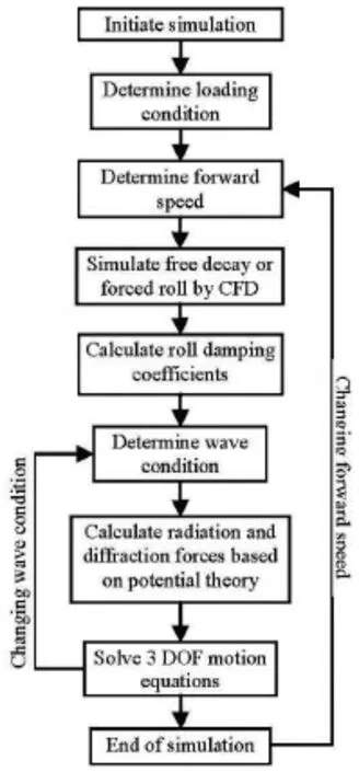
Fig.1 Conceptual scheme of hybrid method for PR assessment
1.1 Theoretical and numerical models
The hybrid method adopts a 3 DOF weakly nonlinear model (roll, heave and pitch) for the simulation of the ship motion. Such kind of models with consideration of the time delay effect and the nonlinearity of Froude-Krylov forces were successfully applied for the simulation of the parametric rolling[7-9]. Motion equations[10]are as follows:
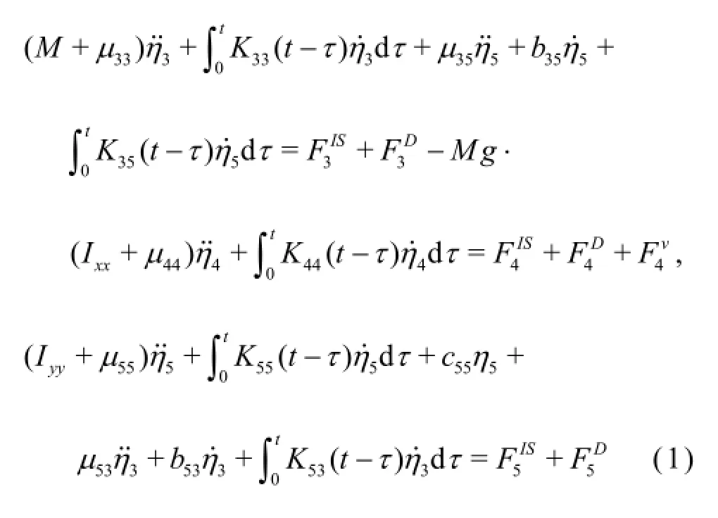
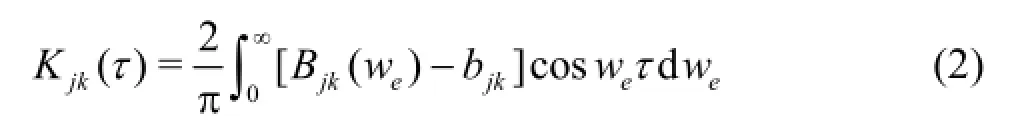
where FISis the composition force of the Froude-Krylov force and the restore force, which are calculated based on the 3-D pressure integration method for the instantaneous wetted hull, the diffraction forces FDare predicted by the 3-D frequency domain potential method, the radiation forces are calculated based on the impulse response theory in the motion equation with consideration of the memory effect as

The roll damping coefficients with/without the forward speed are calculated based on the motion or moment data of the numerical simulations for the free decay or the forced roll of the scaled model. The simulation is carried out by the 3-D CFD solver ISISCFD[11,12]. This flow solver uses the incompressible unsteady Reynolds-averaged Navier Stokes (RANS)equations, based on the finite volume method to build the spatial discretization of the transport equations. The face-based method is generalized to 3-D unstructured meshes, where the non-overlapping control volumes are bounded by an arbitrary number of constitutive faces. The flow solver deals with the multi-phase flows and the moving grids.
The k-ω(SST-Menter) turbulence model is used by the RANS solver, and the adaptive grid refinement method is adopted for capturing the free surface. The 6 DOF motion equations are directly based on the Newton's second law. The forces due to the interaction of the ship and the fluids (water and air) are calculated by integrating the 3-D pressures of the fluids on the hull surface of the ship and updating every time step, then the motions are solved. For the Newton's law, the RANS equations solver is used and the flow/motion coupling is updated each non-linear iteration until a converged solution at each time step is obtained. Then the pressure of the water/air will be calculated for each cell and integrated on the hull of ship.
1.2 Estimation method of roll damping
The free decay and forced roll experiments are usually carried out in the calm water to estimate the roll damping of the ship. In this study, numerical simulations for these two experiments are carried out by the CFD solver for the 3 DOF motions of the 3-D geometry at the model scale. And the roll damping coefficients are obtained by the conventional experimental data processing method.
For simulation of the free decay, the validation for a ship at a forward speed was made in the Gothenburg 2010 Workshop for a bare hull with bilge keels[13]. Zhou et al.[14]validated the simulations for a ship at zero speed with experiments of four test cases at the model scale, including mono-hull ships with/ without complex appendages and a trimaran without appendages. In this study, the simulations for the free decay and the calculations of the roll damping coefficients are performed based on the method developed by Zhou et al.[14].
For the simulation of the forced roll, the forward speed is accelerated from zero to the target velocity. Then the ship is forced to roll following the sinus law,and the roll amplitude slowly reaches the target amplitude to enter the stable rolling stage. Finally, the roll damping coefficient could be calculated by analyzing the moment of roll. The simulation of the forced roll is based on the 3 DOF motions, including roll, pitch and heave. Pitch and heave follows the free trim principle. This means that trim and drafts are not restrained and the ship is to “balance itself” in the water.
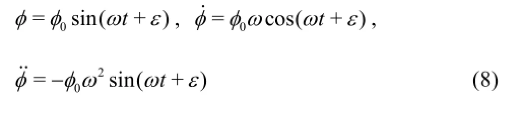
The forced roll motion in the stable stage can be written as
According to the Newton second law, the motion equation and the moment of roll are as follows:
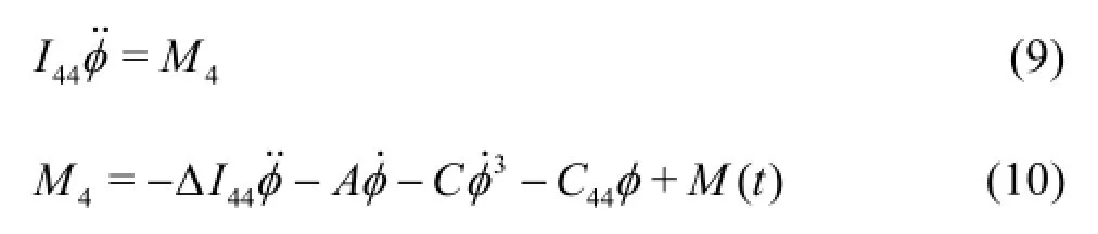
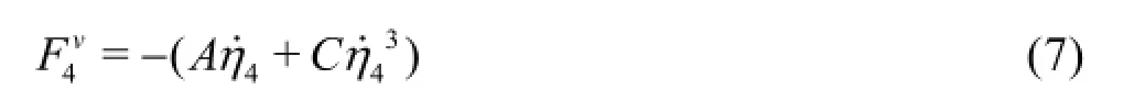
where I44,∆I44are the roll moment of inertia and the added roll moment of inertia,A,C are the roll damping coefficients,C44is the restoring coefficient,M( t)=M0sin(ωt+ε1)is the exciting moment.
Then the moment of roll is calculated by the CFD solver and can be written as
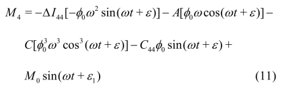
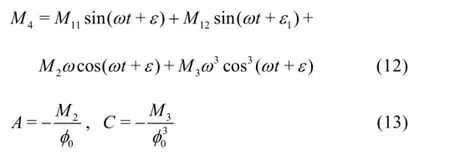
The roll damping coefficients could be calculated by fitting the following formula:
Based on the principle of conservation of energy,the equivalent linear damping could be calculated as
2. Validations and discussions
2.1 Ship model
The well-known container ship C11[15]is adopted for the numerical simulation to validate the hybrid method. Table 1 shows the principal dimensions of C11. Figure 2 shows the 3-D numerical scaled model of C11. The scale factor is 0.01.
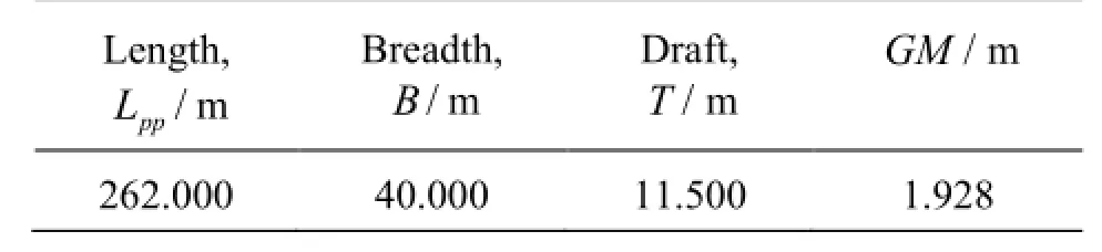
Table1 Principal dimensions of C11 (full scale)
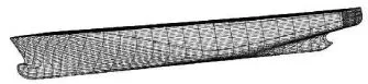
Fig.2 The ship model of C11 containership
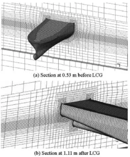
Fig.3 Meshes of typical sections of C11
2.2 Parameter settings and mesh generation
(1) Mesh generation
The simulations of the free decay and the forced roll with/without a forward speed are based on the same mesh. Figure 3 shows the geometries and the meshes of typical sections.
The CFD computation is performed with the samescale factor as in the model test. The computational domain is -4<x<3,-4<y<4,-1.5<z<0.5for the free decay and the forced roll cases, in dimensionless coordinates which are non-dimensionalized by usingLpp. With the scale of the domain, the reflection of the wave-making caused by the forward speed of the ship at domain boundaries can be prevented, and the computational resource can be saved for the simulation of air with little effect on the roll damping. The ship axis is aligned with the x-axis with the bow at x =0.52and the stern at x=-0.48. The free surface lies atz=0. Enough grid points are generated near the free surface to capture the radiation waves and the6extreme motion. All predictions are made on 1.44×10 grids. The size of the grid near the free-surface is taken asLpp/500in the vertical direction,Lpp/50alongx axis, and 4Lpp/10alongyaxis. If the initial roll amplitude or the stable roll amplitude is very large,the sliding grid is essential for simulating the large roll motion. In this simulation, the sliding grid is not used for the simulation of the roll motion.
(2) Parameter settings
The numerical simulation is based on solving the 3 DOF motions (roll, pitch and heave) for the ship in calm water. The forward speed accelerates from zero to the target value following the 1/2sin law, and then keeps as a constant value. The heading is maintained,so the influences of sway and yaw are small and could be neglected.
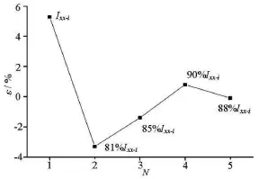
Fig.4 Errors of natural roll period of C11
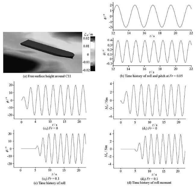
Fig.5 Forced roll simulation of C11
For a blind simulation of the parametric rolling,the initial heel angle or the forced roll amplitude is difficult to determine for the estimation of the roll damping. Therefore, these two values are taken as 20ofor both CFD simulations. This is consistent with the Level 2 criteria of the parametric rolling developed by the IMO[16].
The time step is a key parameter for the accuracy of the numerical simulation of the free decay[14]. In order to achieve an acceptable accuracy and avoid the divergence of the motion solving, 350 time steps per roll period (natural roll period and forced roll period)is adopted. The maximum number of the non-linear iterations is taken as 8, and the convergence criteria of the solver are taken as 2 orders of magnitude. For about 98.37% of cells, the courant number is from 0 to 1.1132.
(3) Estimation of roll moment of inertia
The predictions of the parametric rolling are blind in the sense that the actual roll moment of inertia(Ixx)of the scaled experiment model is not known a priori. This value depends not only on the geometry, but also on the mass distribution inside the geometry. If the exact value of this parameter is unknown, the validation with the measurement data will be problematical, since the predictions of the roll damping and the parametric rolling depend strongly on the accuracy of Ixx[9,14]. Fortunately, the natural roll period is measured during the model test. Since the natural roll period depends on Ixx, it can be used to determine the exact value ofxxI iteratively using the procedure described below.
First, the initial value of Ixxis calculated with Eq.(16)[17]. Then the value of Ixxcould be adjusted based on the error of the natural roll period by simulating the free decay in calm water at zero speed with the CFD approach. Once the iteration ends with a satisfactory accuracy, the appropriate value ofIxxcould be taken for the further prediction of the roll damping and the parametric rolling.
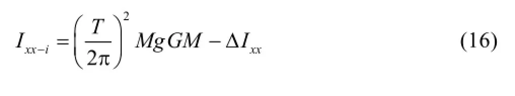
whereT is the natural period of the roll,Ixx-iis the initial value of the roll moment of inertia,∆Ixxis the added roll moment of inertia,M is the mass of the ship,GM is the metacentric height,gis the gravity acceleration. The value of∆Ixxis estimated by the 3-D frequency domain potential method at zero speed.
Figure 4 shows the errors(ε)of the natural roll periods of C11 in the iterative process. The accuracy of Ixxcould reach an acceptable level after 5 iterations.
2.3 Estimation of roll damping
The roll damping coefficients are estimated for Fr=0, 0.05 and 0.10 by simulations of the free decay and the forced roll. Fig.5 and Fig.6 show the simulations of the forced roll and the free decay for C11.φ,θis the amplitude of roll and pitch,Mxis the roll moment.
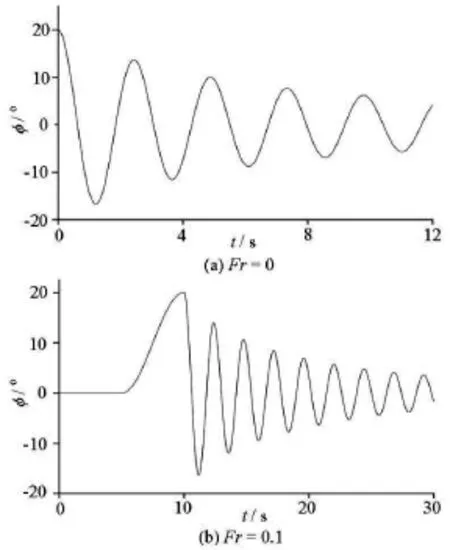
Fig.6 Time history of free decay simulation of C11
Unlike the traditional simulation in 2-D cases,the heave and the pitch are unrestrained in the forced roll motions, thus the simulation results could be in better agreement. The time-domain response of the forced roll (Fig.5(b)) shows that the period of the roll is approximately twice the period of the pitch. This is very similar to the response period relation of the parametric rolling, which is the so-called 2:1 response. This phenomenon indicates that the roll damping characteristics simulated by the forced roll may be closer to the actual parametric rolling.
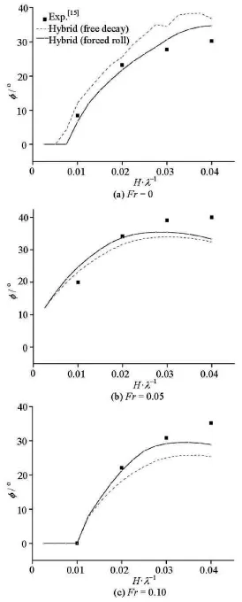
Fig.7 Roll amplitudes predicted for PR
2.4 Validation and discussions of parametric rolling results
Figure 7 shows the predictions of the parametric rolling for C11 by the hybrid method, and Fig.8 shows the time history. These cases include 3 Froude numbers and the range of wave-steepness is from 0.0025 to 0.0400. Both of two options of the hybrid method (free decay and forced roll) are compared with the experiment data.
According to the prediction results of C11 (as shown in Fig.7), with the hybrid method (the forced roll), the parametric roll could be successfully predicted for different speeds and wave-steepness. For cases when those amplitudes are around and less than 27o,a satisfactory accuracy is achieved.

Fig.8 Time history of PR (Fr=0.05, wave-steepness: 0.02)
Small refinements are made for meshes of each simulation of the roll damping with different forward speeds. Thus, the difference of the mesh quality may slightly affect the accuracies in cases at Fr =0.05.
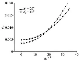
Fig.9 Comparison of effects of initial heel angles on equivalent linear damping coefficients
(1) Influence of damping coefficient with different initial roll angles
The initial heel angle or the forced roll amplitude plays an important role in obtaining the roll damping characteristics such as the equivalent damping coefficients[1]. Figure 9 shows the comparison of the effect of the initial heel angle on the damping coefficients estimated by the simulation of the free decay. In this study, the initial heel angle and the forced roll amplitude are both taken as 20ofor the estimation of the roll damping coefficients. Thus, the agreement is not good for cases with large or small amplitudes as shown in Fig.9. Therefore, it still needs further study how to determine the initial heel angle or the forced roll amplitude for the blind simulation of the PR by the hybrid method. These values could be taken as20otemporarily as is consistent with the 2nd generation criteria of IMO[16].
(2) Influence of roll period
On the other hand, the roll periods of the free decay and the forced roll also affect the estimated roll damping coefficients and the results of the hybrid method. As shown in Fig.7, if the roll damping coefficients estimated by simulating the forced roll, the results of the hybrid method could be in better agreement with the experiment data. This is because the roll period of the forced roll is taken as the roll period of the PR, but the period of the free decay is the natural roll period. So the roll damping characteristics simulated by the forced roll is more close to the actual parametric rolling. Figure 10 shows the influence of the roll period. In this comparison, when simulating the free decay to estimate the roll damping coefficients, the natural roll period of the “free decay-M ” is taken as the roll period of the PR by adjusting the value of Ixx. The results indicate that the roll period could have a significant effect on the prediction of the PR by the hybrid method.

Fig.10 Comparison of effect of roll period on prediction of PR(F r=0)
However, according to the basic assumption of the 2nd generation criteria of the IMO[16], this case is unacceptable to this failure model only if the roll amplitude of the PR is larger than 25o. And the vulnerability of a loading condition is judged by an index weighted according to these critical wave-steepness(for different Froude numbers and wave headings) and the wave scatter diagram of North Atlantic. Therefore,from the view point of engineering application, it is more important to ensure the prediction accuracy of the critical wave-steepness that the roll amplitude of the PR is 25o. According to the present result of C11,it is appropriate to adopt the hybrid method (forced roll) for this purpose, and this method could bring a great advantage in the initial design stage especially in the lack of experiment data for a new design. Of course, further studies of the scale effect are needed to predict the roll damping of the full scale ship properly.
3. Comparison of hybrid, nonlinear dynamics, and direct CFD prediction methods
In this study, in order to investigate the applicability of the proposed hybrid method, two other methods including a non-linear dynamics method and the direct CFD prediction method are utilized to compare with the hybrid method.
3.1 Nonlinear dynamics method
The non-linear dynamics method is adopted as the 2nd check of Level 2 criteria by the IMO[16]for vulnerability judgment of the full scale ships. Due to the fact that the Level 2 criteria are designed for the “early warning” of vulnerability in the design stage, this method is supposed to be simple and conservative predictions are to be obtained. The roll amplitude of the PR is obtained from the analytical solutions of the 1 DOF non-linear dynamics method. So it is very easy to use for engineering applications.
The 1 DOF motion equation is written as:
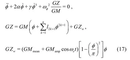
where GZwis the restoring variation due to waves,GMmeanis the mean of the metacentric height variation,GMampis the amplitude of the metacentric height variation,ωφis the natural roll circular frequency,ωeis the encounter frequency; the l2k+1coefficients shall be determined with a least square fit to theGZ curve in calm water,αand γare the non-dimensional damping coefficients that could be estimated by the simplified Ikeda's method[16,18], in the absence of the free decay data. The stable solution could be assumed asis the roll period of the PR,φis the roll angle,GMis the metacentric height in calm water andk!=1· 2…k.
Applying the averaging method, the roll amplitudeAand the phaseεcould be calculated separately by analytical solutions[16,19], as follows

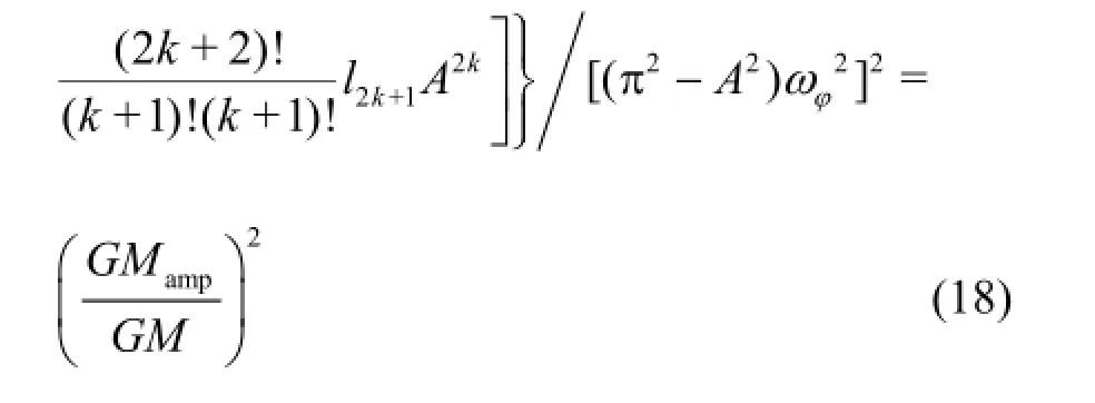
After obtaining the complex solutions in the polynomial form of Eq.(18), the stability of the solutions need to be examined using the Jacobian with respect to the averaged system for the eigen analysis. Finally the effective amplitude of the PR could be obtained.
3.2 Direct CFD prediction method
In order to improve the forecasting precision of the PR for the optimal design, the best way, in theory,is to carry out a good simulation for the encountered wave surface accounting for the action of the ship, the highly nonlinear restoring forces and the hydrodynamic forces, and the large roll-heave-pitch resonance. Different from the traditional potential methods, the fully nonlinear CFD approach could be a good choice for the art of state method for this purpose. Thus, it is also necessary to carry out a comparison study for the hybrid method with the “state of art” methods such as the 3-D direct CFD approach.

Fig.11 Computation domain for prediction of PR (F r=0)

Fig.12 Simulations of PR (Fr=0, wave-steepness: 0.03)
In the direct CFD prediction method, the same RANS solver is used for the estimation of the roll damping. Most of the parameter settings and the mesh generation also follow the same principles. The computational domain is -4<x<2,-1.5<z<0.5, in the dimensionless coordinates non-dimensionalized by usingLpp. All predictions are made on 2.77×10⁶grids. Since the simulations are carried out for the large roll response of the PR, a cylindrical computational domain is created with the sliding grid for simulating the near field of the ship (see Fig.11(a)). We have -0.6Lpp<x<0.6Lpp, and the radius is 1.2 of the depth of the ship. And the grid in the cylindrical domain is refined from-35oto 35oand 145oto 215o(see Fig.11(b)).
The 3 DOF motions (roll, pitch and heave) are the free motions for the simulation of the PR. The forward speed is forced to accelerate from zero to the target value following the 1/2sin law, and then keeps as a constant value sailing in head waves. Sway and yaw are assumed to be neglectable.
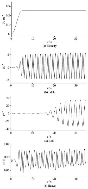
Fig.13 Simulations of PR (Fr=0.05, wave-steepness: 0.02)
Figure 12 shows the time histories ofthe motionresponses and the interactions of the fluid field and the ship at Fr =0.zis the heave amplitude. Figure 13 shows the motion responses atFr =0.05.
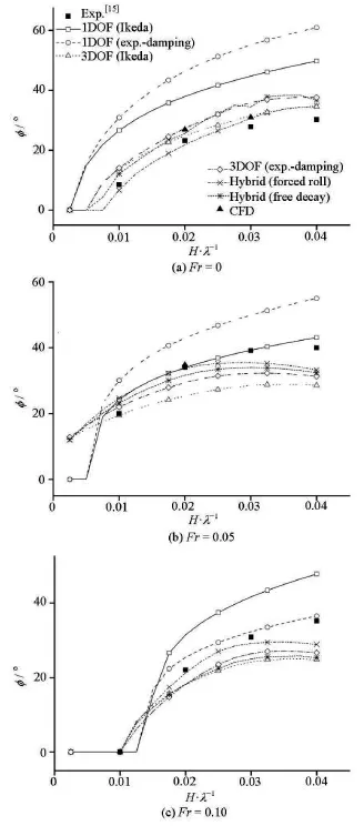
Fig.14 Comparisons of roll amplitudes for PR
3.3 Comparison of hybrid, nonlinear dynamics and direct CFD prediction methods
Figure 14 shows the comparisons of the roll amplitudes predicted by different methods. These methods include the 1 DOF nonlinear dynamics method(Method 1-A, 1-B in Table 2), the 3 DOF potential method with semi-empirical or experimental roll damping (Method 2-A, 2-B in Table 2), the hybrid method(Method 2-C, 2-D in Table 2) and the direct CFD prediction method (Method 3 in Table 2). The roll damping coefficients utilized in the nonlinear dynamics method and the 3 DOF potential method are estimated by the free decay data from the experiment and the simplified Ikeda's method separately. The differences of the results obtained by these methods are shown in Table 2. There are four options for Method 2 that adopt the same 3 DOF potential method for simulating the motion response, but four different methods for estimating the roll damping.
As shown in the results, the 1 DOF nonlinear dynamics method is more conservative than other methods. This is because the nonlinear dynamics method is a highly simplified 1 DOF method and the motion response is obtained by the analytical method. On the contrary, the 3 DOF method and the hybrid method could take account of the nonlinear effect of the Froude-Krylov forces and the effect of heave and pitch in the time domain. Furthermore, the direct CFD prediction method is a fully nonlinear method developed based on the viscous flow theory. This means that in the direct CFD prediction, the viscous effect and the complex nonlinear action between the incident wave and 3 DOF motion of ship are considered.
On the other hand, the predictions of the PR based on the 1 DOF method and the 3 DOF method for the comparison are both very sensitive to the estimation methods of the roll damping coefficients. Thus the calculation method of the roll damping is a key aspect for the prediction of the PR, and this result agrees with the previous studies.
The simplified Ikeda's method is very easy to use,but could also cause uncertainties for the damping prediction as compared with the experiment. These uncertainties make the predicted amplitude of the PR deviate from the results predicted based on the free decay data of the experiment, especially for the nonlinear dynamics method (as shown for Method 1-A and Method 1-B).
In Fig.14, the results of 4 options of Method 2 show the influence of the four estimating methods of the roll damping. The roll amplitudes obtained by Method 2-C (hybrid method) is very close to that obtained by Method 2-B, It indicates that the roll damping estimated by the free decay based on the CFD simulation enjoys a good accuracy for the prediction of the PR, and can be a good option to replace the free decay tests which are currently being carried out.
On the whole, Method 2-D (hybrid method) and Method 3 (direct CFD prediction method) enjoy the best accuracy for the prediction of the PR. Both of them are much more complicated than the nonlinear dynamics method. They aim to solve for the 3 DOF motion responses, taking account the effect of the roll period on the roll damping. They are considered to be more appropriate as the numerical models for the direct stability assessment of the PR as suggested by the IMO[16].
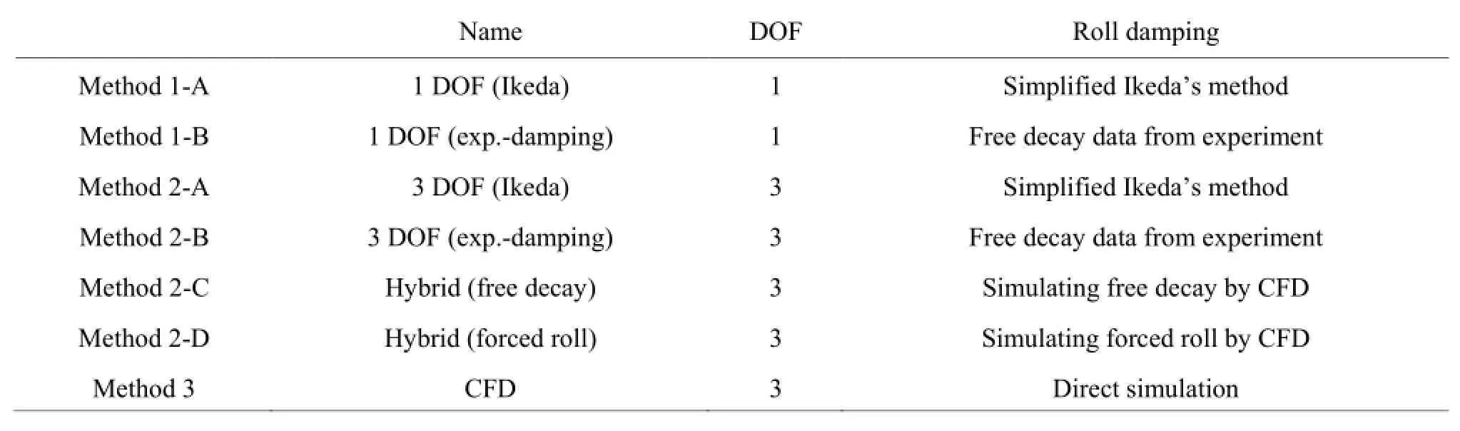
Table 2 Methods for predicting PR
The hybrid method is only based on a weakly nonlinear model, and for the direct CFD prediction method, it is necessary to pay a special attention to the mesh generation and it takes more time to simulate the motion response in regular waves, which is even more complicated than simulating the free decay or the forced roll. It is also necessary to develop a standard procedure for the CFD approach to calculate the roll damping or the direct prediction of the PR. However,this means that sufficient experimental data are needed for validation. For the former, the free decay and forced roll tests have been conducted for many years, no matter whether these ships are vulnerable to the PR. Therefore, we will suffer a more serious data shortage problem, if we adopt the direct CFD prediction method. Therefore, the hybrid method is a better option for the direct stability assessment of the PR.
4. Conclusions
A hybrid method is developed and validated for predicting the parametric rolling in this study. Comparison study is also carried out with two methods, and their advantages are shown. The following conclusions are drawn:
With the hybrid method, the roll damping efficiently can be estimated efficiently and the PR be predicted with a good accuracy. The roll damping estimated by simulating the forced roll is more flexible in simulating the damping characteristics of the PR, thus with the hybrid method, better agreement could be achieved. In addition, with the hybrid method, similar accuracy could be achieved but with far less computational time than the direct CFD prediction method.
Therefore, the hybrid method could be a good option for the direct stability assessment of the PR in the near future, and could be utilized for the optimization of the ship design, especially in the initial design stage.
References
[1] FOSSEN T., NIJMEIJER I. H. Parametric rsonance in dynamical systems[M]. New York, USA: Springer, 2012.
[2] HASHIMOTO H., UMEDA N. A study on quantitative prediction of parametric roll in regular waves[C]. Proceedings of the 11th International Ship Stability Workshop. Wageningen, The Netherlands, 2010.
[3] UMEDA N., HASHIMOTO H. and MINEGAKI S. et al. An investigation of different methods for the prevention of parametric rolling[J]. Journal of Marine Science and Technology, 2008, 13 (1): 16-23.
[4] YANG Chun-lei, ZHU Ren-chuan and MIAO Guo-ping et al. A roll damping prediction method of three-dimensional ships based on CFD computation[J]. Journal of Shanghai Jiaotong University, 2012. 46(8): 1190-1202(in Chinese).
[5] WILSON R. V., CARRICA P. M. and STERN F. Unsteady RANS method for ship motions with application to roll for a surface combatant[J]. Computers and Fluids,2006, 35(5): 501-524.
[6] SADAT-HOSSEINI H., STERN F. and OLIVIERI A. et al. Head-wave parametric rolling of a surface combatant[J]. Ocean Engineering, 2010, 37(10): 859-878.
[7] TURAN O., AYAZ Z. Parametric rolling behaviour of azimuthing propulsion-driven ships[J]. Ocean Engineering, 2008, 35(13): 1339-1356.
[8] CHANG Yong-quan, FAN Ju and ZHU Ren-chuan et al. Analysis of ship parametric rolling in head sea[J]. Chinese Journal of Hydrodynamics, 2008, 23(2): 204-211(in Chinese).
[9] ZHOU Yao-hua, MA Ning and GU Jie-chong. Effect of calculation methods of roll moment of inertia on sensitivity prediction of parametric rolling for container ships[J]. Shipbuilding of China, 2013, 54(3): 11-20(in Chinese).
[10] ZHOU Yao-hua. The prediction of roll damping and nonlinear motion of trimaran[D]. Master Thesis. Harbin, China: Harbin Engineering University, 2010(in Chinese).
[11] Deng G. B., QUEUTEY P. and VISONNEAU M. RANS prediction of the KVLCC2 tanker in head waves[C]. Proceedings of the 9th International Conference on Hydrodynamics. Shanghai, China, 2010.
[12] DENG G. B., QUEUTEY P. and VISONNEAU M. Seakeeping prediction for a container ship with RANS computation[C]. Proceeding of the 9th National congress on Hydrodynamics and 22nd National conference on Hydrodynamics. Chengdu, China, 2009.
[13] LARSSON L., STERN F. and VISONNEAU M. CFD in Ship hydrodynamics-Results of the Gothenburg 2010 Workshop[C]. The Gothenburg 2010 Workshop. Gothenburg, Sweden, 2010.
[14] ZHOU Yao-hua, MA Ning and SHI Xun et al. Direct calculation method of roll damping based on three dimensional CFD approach[J]. Journal of Hydrodynamics,2015, 27(2): 176-186.
[15] LU J., UMEDA N. and MA K. Predicting parametric rolling in irregular head seas with added resistance taken into account[J]. Journal of Marine Science and Technology, 2011, 16(2): 462-471.
[16] IMO. Information collected by the correspondence group on intact stability regarding the second generation intact stability criteria development[C]. Sub-Committee on Ship Design and Construction (SDC) 1st session. London,UK, 2014.
[17] LI Ji-de. Ship seakeeping performance[M]. Harbin,China: Harbin Engineering University Press, 2007(in Chinese).
[18] KAWAHARA Y., MAEKAWA K. and IKEDA Y. A simple prediction formula of roll damping of conventional cargo ships on the basis of Ikeda's method and its limitation[C]. Proceedings of the 10th International Conference on Stability of Ships and Ocean Vehicles. St Petersburg, Russia, 2009, 387-398.
[19] MAKI A., UMEDA N. and SHIOTANI S. et al. Parametric rolling prediction in irregular seas using combination of deterministic ship dynamics and probabilistic wave theory[J]. Journal of Marine Science and Technology,2011, 16(3): 294-310.
10.1016/S1001-6058(16)60666-2
December 9, 2014, Revised August 17, 2015)
* Project supported by the Ministry of Industry and Information Technology of China (Grant No. [2012]533), the Chinese Government Key Research Knowledge-based Ship Design Hyper-Integrated Platform (Grant No. 201335).
Biography: Yao-hua ZHOU (1984-), Male, Ph. D., Engineer
Ning MA,
E-mail: ningma@sjtu.edu.cn
2016,28(4):617-628
猜你喜欢
杂志排行

水动力学研究与进展 B辑的其它文章
- Effect of some parameters on the performance of anchor impellers for stirring shear-thinning fluids in a cylindrical vessel*
- Numerical simulation of flow characteristics for a labyrinth passage in a pressure valve*
- Effect of head swing motion on hydrodynamic performance of fishlike robot propulsion*
- A parameter analysis of a two-phase flow model for supersaturated total dissolved gas downstream spillways*
- Prediction of oil-water flow patterns, radial distribution of volume fraction,pressure and velocity during separated flows in horizontal pipe*
- Motion and deformation of immiscible droplet in plane Poiseuille flow at low Reynolds number*