Research and optimization on the venturi tube dynamic throttling element of new flowmeter
2015-12-19JianmeiDINGHaiWANGCollegeofMechanicalandElectricalEngineeringNortheastForestryUniversityHarbin150040China
Jian-mei DING,Hai WANG(College of Mechanical and Electrical Engineering,Northeast Forestry University,Harbin 150040,China)
Research and optimization on the venturi tube dynamic throttling element of new flowmeter
Jian-mei DING*,Hai WANG
(College of Mechanical and Electrical Engineering,Northeast Forestry University,Harbin 150040,China)
According to the working process of dynamic throttling element flowmeter,the Reynolds number keeps constant when the flow is steady.The way to change the pressure drop is to change the local pressure loss.Based on the Fluent software,it has been analyzed that how the structure parameters of venturi tube influence the pressure drop.With the completion of flowmeter prototype,the dynamic throttling element was tested by using a kind of binary flow calibration platform.According to the test results,it could conclude that the optimization could perfectly meet the real flow condition.
Flowmeter,Venturi tube,Pressure drop
Hydromechatronics Engineering
http://jdy.qks.cqut.edu.cn
E-mail:jdygcyw@126.com
1 Introduction
The small diameter of pipeline and impurities in our heating supply system makes the normal flowmeters hard to work,such as vortex flowmeter,turbine flowmeter,electromagnetic flowmeter and the differential pressure flowmeter with holes.To meet the demand of heat metering,we design a kind of new flowmeter based on dynamic throttling element.The core component of the flowmeter is a venturi tube with two metal diaphragms.A very important parameter which affects the performance of the new flowmeter is the pressure drop between inlet pressure and outlet pressure,so we focus on the throttling performance of venturi tube.With the help of Fluent software,we analyze the parameters which affect the pressure drop,and obtain a kind of venturi tube which could be used in the new flowmeter.
2 Technology analysis
The schematic shown in Fig.1 is the working status of dynamic throttling element.
When the fluid flows through the dynamic throttling element,a pressure drop will occur.At the same time,the fluid will impose a driving force to the dynamic throttling element.So we can calculate the flow rate by detecting the driving force.Because the pressure drop is produced by the dynamic throttling element,the key point is to analyze how the dynamic throttling element affects the pressure drop.
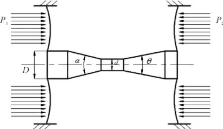
Fig.1 Working status of dynamicthrottIing eIement
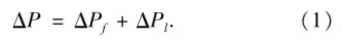
As we can see from Fig.1,the venturi tube is made up with a contraction tube and an expansion tube.According to the principle of fluid dynamics,the pressure drop ΔP generated by the throttling element could be divided into two parts,the friction pressure loss ΔPfand the local pressure loss ΔPl.For the application of engineering,we assume that the two kinds of pressure losses could be calculated,respectively.So we can get the relationship as shown in the Eq.(1):
The friction pressure loss could be calculated by the original cross-section without deformation.The parameters which affect the friction pressure loss are listed as follows:the diameter of pipeline d,the length of pipeline l,the average rough height e,the average flow velocity v,fluid density ρ,and the viscosity coefficient μ,as shown in the Eq.(2):
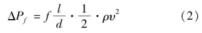
Where,f is the friction pressure loss coefficient,f is the function of Reynolds number Re and relative roughness e/d.
In the heating supply system,the Reynolds number is in the range of 5 000<Re<50 000.According to the Stanton Chart,the average rough height e has nothing to do with the friction pressure loss coefficient.So only the Reynolds number affects the friction pressure loss coefficient,as shown in the Eq.(3):
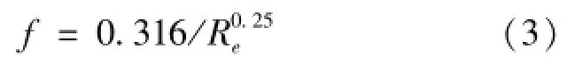
The Reynolds number Re could be determined by the flow,so the friction pressure loss is completely determined by the flow in the new flowmeter.
Local pressure loss is generated by the deformed cross-section,as shown in the Eq.(4):
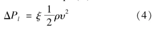
Where,ξ is the so-called local pressure loss coefficient,this value is mainly determined by the structural parameters of the element which affect the local pressure loss.The Reynolds number and average rough height do hardly affect ξ.The structural parameters of venturi tube are the diameter ratio β=D/d,the contraction angle α and expansion angle θ[2].
In a word,the Reynolds number keeps constant when the flow is steady,so the way to change the pressure drop is to change local pressure loss.Therefore,we mainly analyze how the structural parameters affect the pressure drop.
3 Simulations based on Fluent
By changing different parameters,we can build different 3-D models of flow flied in new flowmeter with the help of Solidworks software.Firstly,import the models into the pretreatment software(Gambit)of Fluent;secondly mesh the models and set boundary condition;finally,import the models into fluent 3D solver to compute.
Boundary condition.In the heat supply system,Reynolds number is usually greater than 4 000.So the fluid in the flowmeter is turbulent.According to Reynolds number,we select the k-ε double function model as the turbulence computation model.Because water is a kind of incompressible fluid,we set inlet velocity as the inlet condition,outflow as the outlet condition,and the wall as the cylindrical and conical surface[3].Under the inlet condition of turbulence,we need to determine turbulence parameters.Turbulence parameters could be calculated as follows.
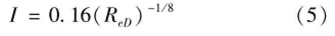
Firstly,the turbulence intensity I could be determined as shown in the Eq.(5):
The turbulence length scale could be evaluated in the Eq.(6):
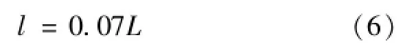
Where,L is the hydraulic diameter,the hydraulic diameter of circular pipeline is the inner diameter of pipe.
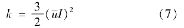
Secondly,the turbulence kinetic energy k could be obtained by the average flow velocity¯u and the turbulence intensity I as shown in the Eq.(7):
Finally,we can obtain the turbulent dissipation rate ε as shown in the Eq.(8).
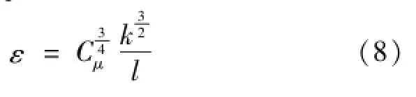
Where,Cμis an empirical constant and it has the value of 0.09.
Under different flow,the turbulence parameters can be listed as Table 1.
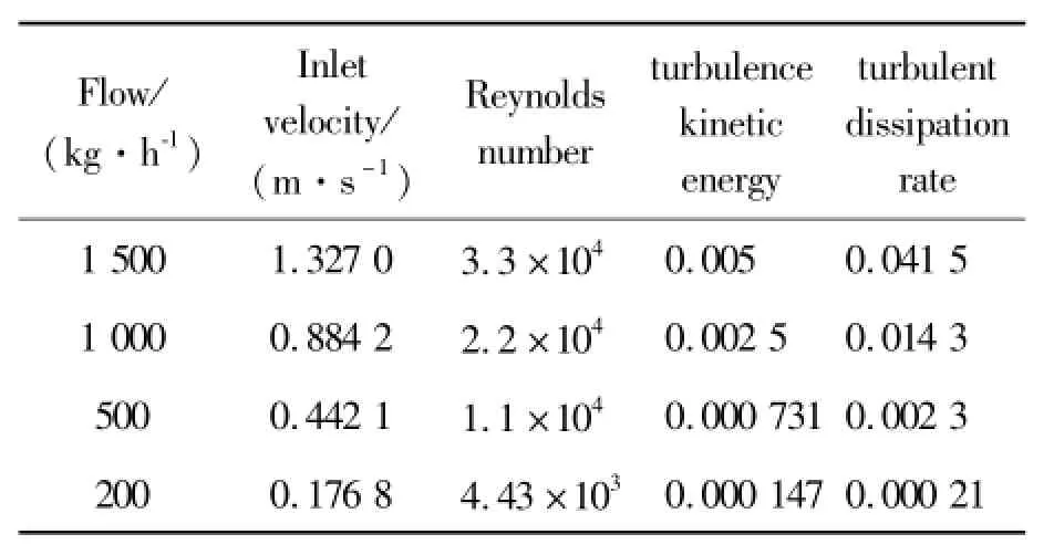
TabIe1 The turbuIence parameters
CaIcuIation resuIts.Fig.2 shows the relationships between the diameter ratio β and the pressure drop. Where,the flow remains 1 500 kg/h,the contraction angle is 20°,the expansion angle is 10°,the diameter of inlet pipeline is 20 mm.According to Fig.2,we can obtain that the smaller β,the larger pressure drop.Basically the relationship is a negative four function.
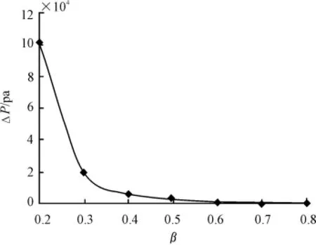
Fig.2 The reIationship between the diameter ratioβ and the pressure drop
Fig.3 shows the relationships between the contraction angle α and the pressure drop.Where,the flow remains 1 500 kg/h,the diameter ratio β is 0.5,the expansion angle is 10°,the diameter of inlet pipeline is 20 mm.According to Fig.3,the pressure drop varies little when the contraction angle is less than 40°,so we can ignore the change of pressure drop.With the contraction angle α becoming greater but less than 160°,the pressure drop generated by the venturi tube starts to become greater.Basically,the relationship is a linear function.When the contraction angle is greater than 160°,the pressure drop varies little.
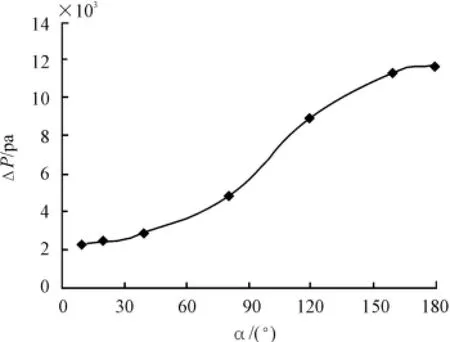
Fig.3 The reIationship between contraction angIeα and the pressure drop
Fig.4 shows the relationships between the expansion angle θ and the pressure drop.Where,the flow remains 1500 kg/h,the diameter ratio β is 0.5,the contraction angle is 20°,the diameter of inlet pipeline is 20 mm.According to Fig.4,the pressure drop varies little when the expansion angle is less than 30°,so we can ignore the change of pressure drop.With expansion angle θ becoming greater but less than 120°,the pressure drop generated by the venturi tube change to be greater.Basically,the relationship is a linear function.When the contraction angle is greater than 120°,the pressure drop varies little.
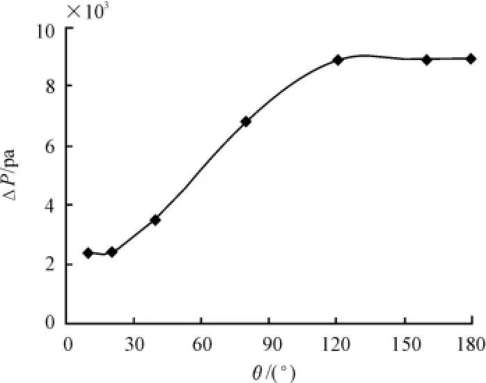
Fig.4 The reIationship between the expansion angIe θand the pressure drop
Design and simuIation of dynamic throttIing eIement.When the contraction angle is less than 40° and the expansion angle is less than 30°,the pressure drop change little.So we select the contraction angle and the expansion angle of the new flowmeter with good manufacturability.Finally,the contraction angle is chosen to be 20°,the expansion angle is chosen to be 10°.Analyze the different pressure drop under different flow circumstance by using the Fluent software. At last,draw a flow-pressure drop curve based on the analysis results,as shown in Fig.5.
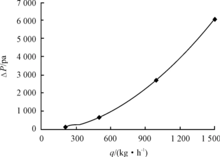
Fig.5 The fIow-pressure drop curve
4 Experimental results and analysis
Make a venturi tube with the structural parameters listed in the former chapter,and fix the venturi tube to the new flowmeter.Test the performance of new flowmeter by using a kind of binary flow calibration platform[4].Acquire the different height of front pressure pipe and behind pressure pipe.Calculate the pressure drop with height differences.Draw the flowpressure drop curve as shown in Fig.6.
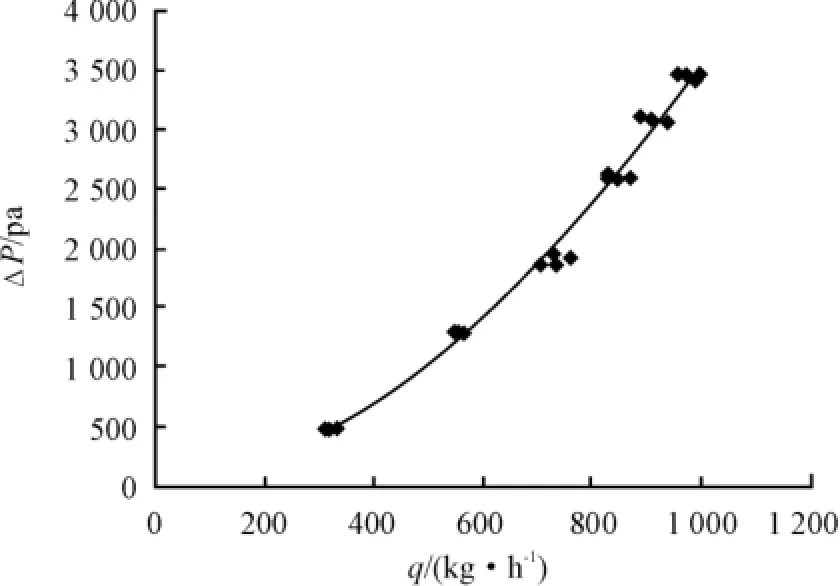
Fig.6 The test resuIt of fIow-pressure drop curve
Compare the Fig.5 with the Fig.6,we can find that the theoretical curve of flow-pressure drop is slightly less than the testing curve.The reason is that there is pipe connectors between the front pressure port and the behind pressure port,thus the error could be introduced to the final result,but the error will become smaller as soon as the flow is getting smaller.
5 Summary
With the simulation of Fluent software,we found the relationships between structural parameters and pressure drop for flowmeter.According to the theoretical analysis,the structure of dynamic throttling element could be optimized.Finally,compare the theoretical analysis with the experimental results,and the difference between could be explained.The results verify the correctness of numerical analysis,and have real meaning for the development of new flowmeter.
[1]Zhu Y K.Hydromechanics Basis[M].Beijing:Beihang University Press,1990.
[2]Sun W Q,Wang J Z.Designing Handbook of throttling element in flow measurement[M].Chemical Industry Press,2004.
[3]Wang F J.Analysis of Computational Fluid Dynamics:Principles and Applications of CFD Software[M].Beijing:Tsinghua University Press,2004.
[4]Lian X.Experimental Study on New Dynamic Throttling Flow of Central Through Holes[D].Harbin:Harbin Institute of Technology,2011.
新型流量计动态节流元件文丘里管的研究与优化
丁建梅*,王 海
东北林业大学机电工程学院,哈尔滨 150040
根据动态节流元件流量计的工作过程,在雷诺数保持不变时流动是稳定的,改变流量压降可测得流量计局部压力损失。基于Fluent软件,分析了文丘里管的结构参数对压降的影响,并根据供热系统的实际情况选择了一组元件匹配合理的文丘里管参数。流量计样机完成后,通过使用二进制流量校准平台测试动态的节流元件。根据试验结果,优化也能较好地满足实际流动的条件。
流量;文丘里管;压力差
10.3969/j.issn.1001-3881.2015.12.002Document code:A
TH814
20 December 2014;revised 6 February 2015;accepted 11 March 2015
*Corresponding author:Jian-mei DING,Professor.
E-mail:djm801@126.com
猜你喜欢
杂志排行

机床与液压的其它文章
- Research of numerical simulation on the spatial distribution of plasma antenna radiation field based on MATLAB
- Failure analysis for spindle system of CNC machine tools based on FMECA
- A valve can be designed to stabilize the gas-liquid flows
- The CNC transformation of CA6140 lathe based on motion controller
- Simulation analysis for punching machine driven by linear motor
- Application of improved PSO-based to neural network control system of parallel mechanism