Low-Cost Wireless Sensor Network Node Design for Multi-Point Bolt Loosening Detection
2015-11-21XuYunpeng徐云鹏WuJian吴键ShangFei商飞HeBoxia何博侠
Xu Yunpeng(徐云鹏),Wu Jian(吴键),Shang Fei(商飞),He Boxia(何博侠)
School of Mechanical Engineering,Nanjing University of Science and Technology,Nanjing 210094,P.R.China;
Low-Cost Wireless Sensor Network Node Design for Multi-Point Bolt Loosening Detection
Xu Yunpeng(徐云鹏),Wu Jian(吴键)*,Shang Fei(商飞),He Boxia(何博侠)
School of Mechanical Engineering,Nanjing University of Science and Technology,Nanjing 210094,P.R.China;
Bolted connections are commonly used in aerospace structures.Once the bolts on the aircraft are damaged or loose,the consequence will be disastrous.Therefore,monitoring bolt loosening is especially required. However,periodic manual inspection costs much money and time.And it is very difficult to achieve multi-point monitoring for many bolted structures in an aircraft.Therefore,a low-cost,reliable detection method based on wireless sensor networks is presented.The reed switch is selected as a sensor for bolt loosening monitor.The chip PT2262 and PT2272 are chosen as hardware codec chip for multi-point placement.A wireless transmitter and receiver circuit is designed on 315 M Hz frequency.The codec chip and the wireless transmission are triggered by the reed switches.Bolt loosening is detected by the receiving terminal and indicated by light and sound alarms.The wireless transmitter and the receiver circuit are tested and the monitoring system is verified by experiments.The results show that bolt loosening can be effectively detected within 300 m.The developed sensor network is expected to solve multi-point bolt detection problems and provide a low-cost and reliable monitoring technology.
bolt loosening;multipoint monitoring;wireless sensor network
0 Introduction
Bolt joints on large-scale steel structure and equipment are widely used in aerospace[1],civil,mechanical,chemical and other industries[2-3]. Therefore,monitoring bolt loosening is particularly important.The torque wrench method,resistance strain gauge electric method,and optical mechanics method are commonly used for bolt fastening force testing.Among them,the torque wrench method is often used to control bolt fastening force.However,due to the existing friction among structure,it is difficult to achieve accurate measurement.As for resistance strain gauge method,the resistance strain gauge is mounted on bolts to realize accurate measurement,but it is difficult to achieve in many occasions due to its constraints of installation form[4-6].
Wireless sensor network(WSN)are deployed in the monitored area by the large number of cheap micro-sensor nodes and wireless communication.The sensing target information in network coverage area is collected and processed by sensor,and sent to the viewer.A wireless sensor network is constituted of sensors,perception of objects and observers[7-8].
In engineering applications,the bolts on large equipment may subject to repeated impact and vibrations of external forces.Meanwhile,the bolts may be stretched for a long time which results in tension reduction.Due to these factors,it is difficult to avoid bolts loosening in large-scale equipment such as aircraft.As time goes on,even tiny loosening in the initial stage may cause unimaginable disaster accident.
The acoustic elastic phenomenon was discovered in 1940.The study of monitoring bolts loosening based on acoustic elastic effect has beenlaunched by many domestic and foreign scholars. The nondestructive detection method in bolt space by using acoustic elastic phenomenon was proposed by Derek Doyle,Andrei Zagrai et al[9].Liu Zhenqing of Tongji University aimed at measuring axial bolt fastening force with ultrasonic technology[10].However,the change of the velocity of sound in bolt is tiny,and high precision tracking measuring instrument is required.It is difficult to be widely applied in industrial field[11-12].
At the same time,monitoring bolt connection state based on piezoelectric materials active sensing methods was also carried out in the study[13-14].Yang and Chang realized the bolt loosening detection plate with piezoelectric active sensor[15].The loss of fastening force of bolt loosening could be measured accurately by the system. Eurther,the basic location of loose bolts in bolt group based on piezoelectric impedance effect was designed by Ye Liang et al.from Beijing University of Chemical Technology[16].
In 2011,the South Korea Institute of architecture and engineering[17]proposed an active monitoring system of bolts loosening.This system was used for monitoring bolt loosening of Korean domestic bridge bolt connection,without the need for manual regular monitoring.ZigBee RE module was triggered by loose bolts and the signal was received by engineering staff so that they could carry out the inspection and maintenance. Meanwhile,this monitoring method was more timely and effective.
1 Hardware System
A mechanical reed switch is adopted as bolt loosening detection sensor with only two states:On or off.Meanwhile,wireless receiver based on frequency of 315 MHz and transmitter circuits are designed.Data are transmitted in the form of bit rather than frame in this circuit.The power consumption and cost can be reduced by using this circuit.At the same time,the reliability will be improved.In addition,the PT2262 and PT2272 chips are selected as hardware codec encoder. LED is chosen as an indicating device to show the monitoring result of bolts loosening.
1.1 Detection system
Monitoring system is composed of bolt loosening detection circu,wireless receiver and transmitter circuits.The schematic diagram of bolt loosening monitoring system configuration is shown in Eig.1.

Eig.1 Schematic diagram of bolt loosening detection system configuration
The rotation angle of the screw nut is measured by the system.When bolt loosening does not occurre or the screw nut rotation angle is in safety range,the reed switch will be turned off and the monitoring system will not be triggered. Once the rotation angle of the screw nut exceeds the safe range,the reed switch will be turned on and the monitoring system will be energized.I-dentification number(ID)of loose bolt is encoded by hardware.Then the encoded information is sent to manager terminal of information collection system by wireless transmitter circuit.The information can be received by wireless receiver circuit and decoded.At last,the LED corresponding to the loose bolt ID is lighted.
In engineering applications,hardware encoding is easier than software encoding.Data input of the encoder is realized by using dial switch in the detection circuit.It is worth mentioning that the installation of the detection device is much easier.Meanwnile,since the monitoring system is not energized when bolt loosening does not occurr,the power consumption is reduced.
1.2 Bolt loosening detection method
Reed switch is taken as the sensor to realize bolt loosening detection.It is consisted of two thin metal contactors encapsulated in a glass tube,as shown in Eig.2.It is a special magnetic sensing switch that turns ON/OEE according tothe change of intensity of surrounding magnetic field.Once the reed switch is turned on,wireless transmitter circuit will begin to work.The operating principle of reed switch is shown in Eig.3. When the magnetic field remains in equilibrium,the switch is OEE.And when the field is biased,the switch is ON.

Eig.2 Reed switch of monitoring

Eig.3 Principle of monitoring
1.3 Wireless receiver and transmitter circuits
1.3.1 Wireless transmitter circuit
Data transmission module is designed to operate at 315 M Hz.Surface acoustic wave(SAW)resonator is used for frequency stabilization.Erequency drift is only 3×10⁻⁶Hz/℃when the temperature is between-25—+85℃and this is important for the multiple wireless remote control and data transmission systems.A data modulation transistor Q1is added in the transmission circuit.This structure makes it easy to connect with other modules without considering voltage of circuit and the value of output signal.The modules include fixed coding circuit,rolling code circuit and interface circuit between single-chips. Eor example,the output pin of data can be directly connected to the input pin of data module with using PT2262,as shown in Eig.4.
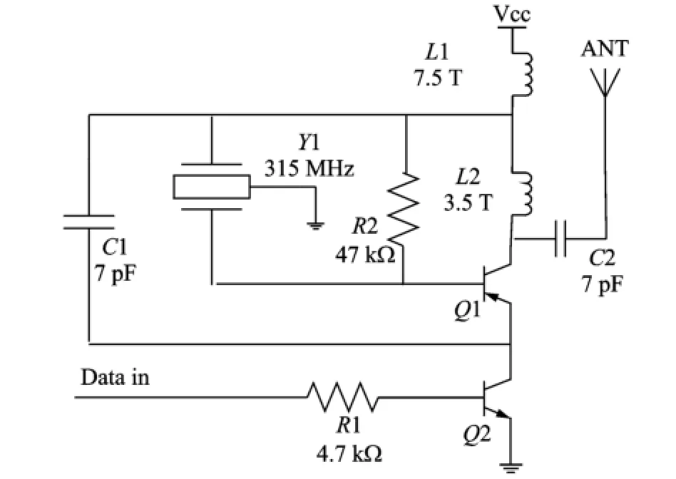
Eig.4 Wireless transmitter circuits
1.3.2 Wireless receiver circuit
Receiver circuit is designed as the super-heterodyne circuit because lower cost and power is needed in the super-heterodyne circuit.Receiver circuit is used to operate at voltage of 3 V and quiescent current of 0.2 m A.The sensitivity of receiver is-95 d Bm,as shown in Eig.5.
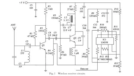
Eig.5 Wireless receiver circuits
2 Software Decoding and Host-Com-Puter Software
2.1 MCU software design
In the experiment,software is realized by MSP430 MCU.The synchronization code is designed for communication judge and to identify the pulse width.Program flow chart of software decoding is shown in Eig.6.
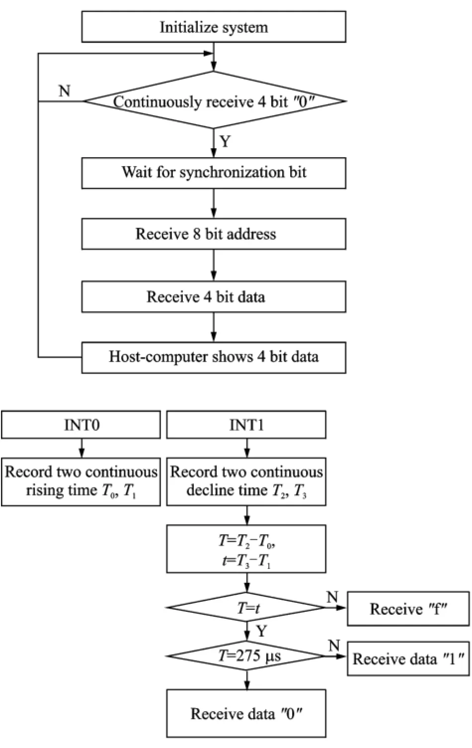
Eig.6 Software flow
2.2 MCU hardware circuit design
MCU receiving circuit is composed of the wireless receiving module,signal transform module and MSP430 MCU.The wireless module is used to receive,demodulate,amplify and shape data.At the same time,the output of the module is digital signal which can be compatible with TTL signal.The signal transform module is supposed to complete the signal isolation,coding phase and provide the interrupt signal for MSP430 MCU.Design of the hardware circuit is shown in Eig.7.
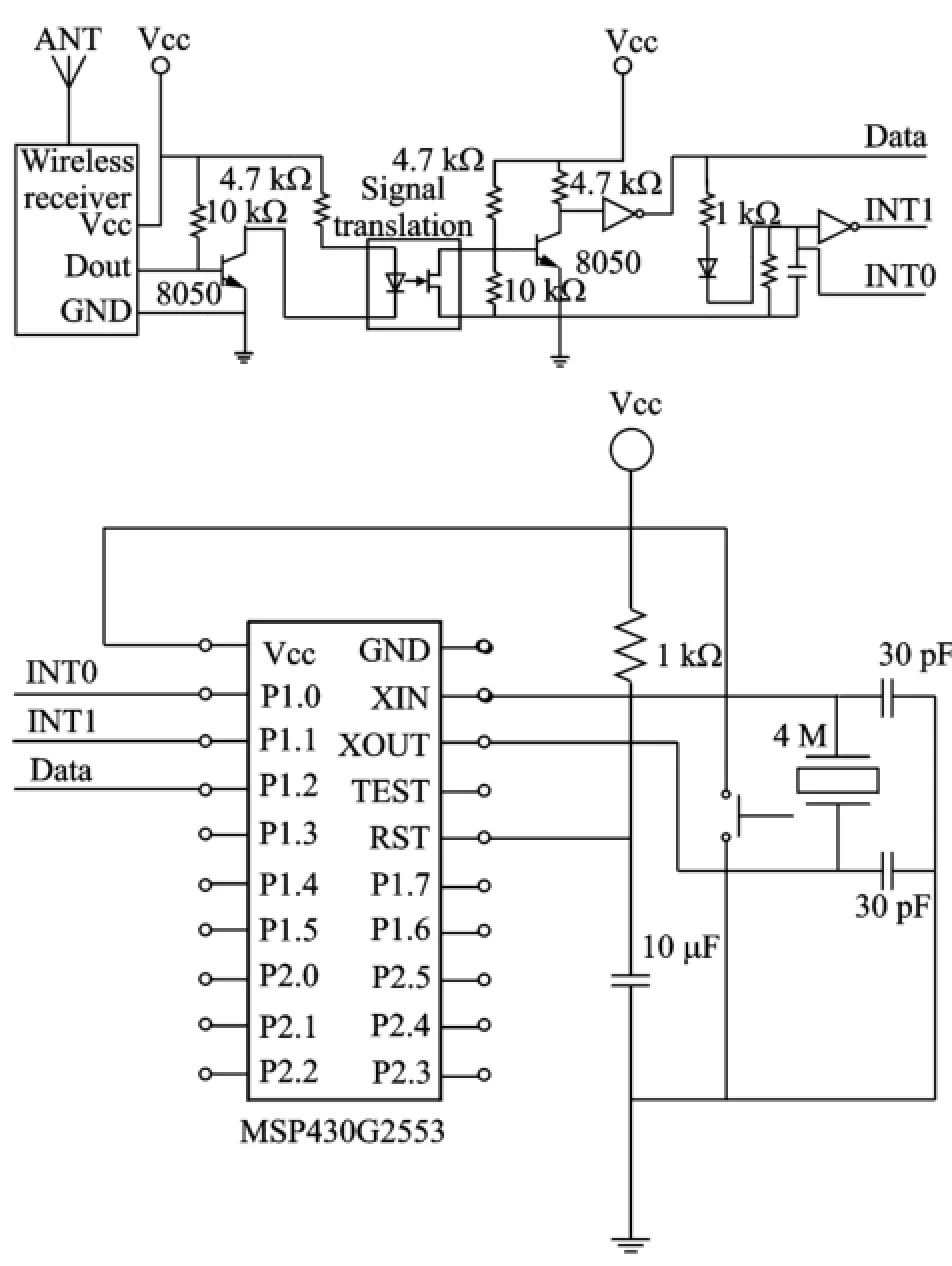
Eig.7 Hardware circuit
2.3 Host-comPuter design
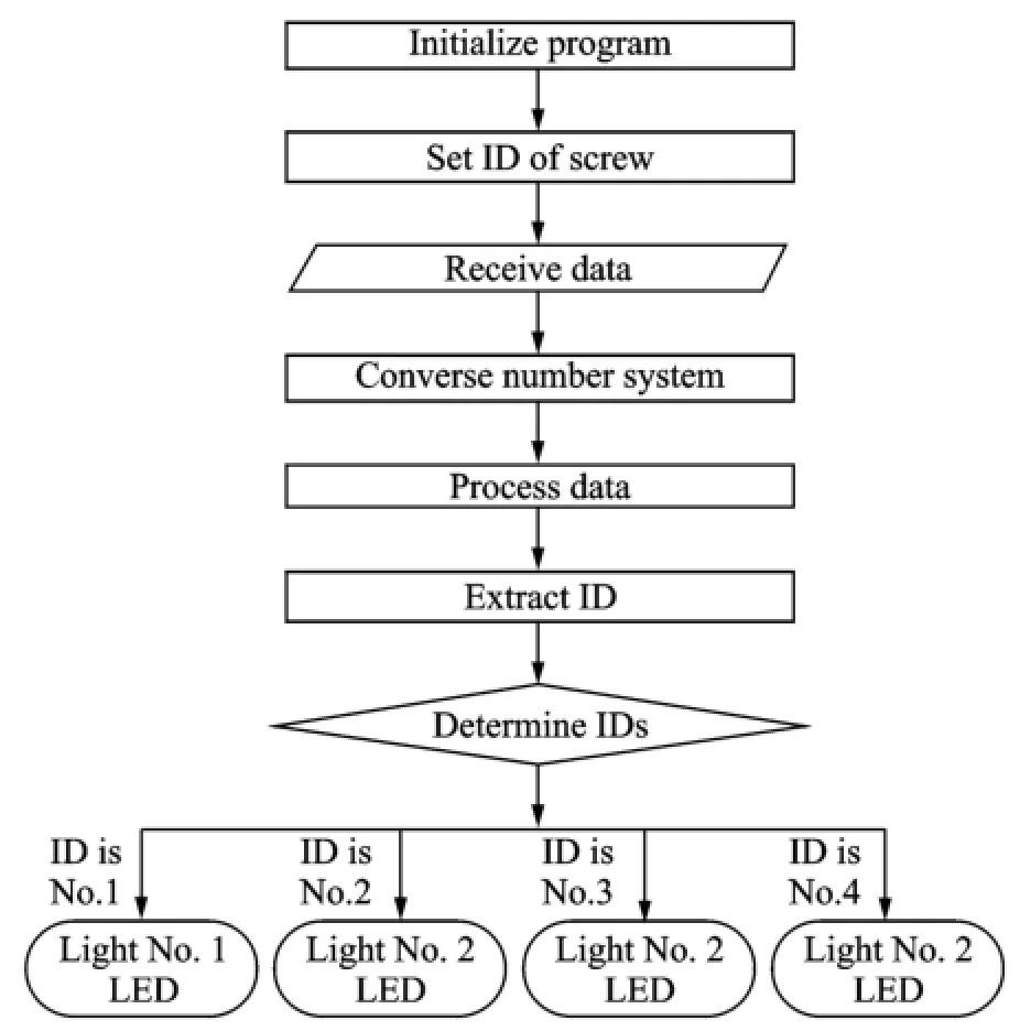
The program of up-lever computer is written by Lab VIEW.The VISA widget is used in the up-lever computer and hexadecimal data are received and converted to decimal.Eour detected bolts are designed in the experiment.Therefore,four corresponding decimal data are received by PC terminal.IDs and data encoded by PT2262 are included in the decimal data.When the decimal data are received,corresponding lights in the host-computer is ON which means the bolt is loose.Program flow chart is shown in Eig.8.
3 ExPeriment and Result Analysis
3.1 Wireless module transmitted distance and sPectrum analysis
The wireless transmitting distance is mainly affected by the output power of RE transmitter,the receiver sensitivity of the receiving circuit,the anti-interference ability of the system,and the receiving capacity of antenna.The output power of the transmitter and the noise intensity is relevant to the supply voltage.Therefore,the re-lation between the supply voltage and the transmitting distance is focused on here.The actual transmitting distance and spectrum analysis is tested under different supply voltage.
Eig.8 Elow chart of host-computer
The working voltage range of wireless receiver and transmitter circuits is+3—+12 V.The hardware encoding transmitted distance of wireless receiver and transmitter circuits is compared under the voltage of 3,6 and 12 V.It is shown in Table 1.

Table 1 Hardware encoding transmitted distance
The software encoding transmitted distance under different supply voltages is compared in Table 2.It can be known from Tables 1,2 that the software encoding transmitted distance is shorter than the hardware encoding with the same supply voltage,due to the electromagnetic interference of receiving circuit from MSP430.The receiving circuit is also interfered by magnetic field. When using software decoding,software decoding circuit is affected much easier than the hardware decoding circuitry because of the presence of MSP430 MCU.
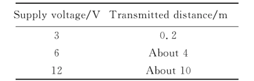
Table 2 Software encoding transmitted distance
In addition,from the analysis of the experimental results,the phase noise of the wireless receiver and the transmitter circuits under the supply voltage 3 and 6 V is smaller than that under 12 V.The large frequency noise and low spectrum purity are existent under supply voltage 12 V,therefore,3 and 6 V supply voltages are better choices.According to the hardware coding launch distance under different voltages,the power supply voltage of the detection circuit for experiments is 6 V.The spectrum analysis of the DE data transmitter module under the supply voltage 3,6 and 12 V is shown in Eig.9.
3.2 ExPeriment of bolt loosening detection
According to the analysis above,a circuit board with four bolts is designed as experimental model.Each bolt is signed a number.The square magnet is attached to one side of the screw nut. When the screw nut is rotated,the magnet on bolts is correspondingly rotated,and thus the magnetic field is changed.As a result,the reed switch on detection system is triggered and the system is energized,finally.The detection system of each single bolt in experiment is shown in Eig.10.
Experiment is divided into two groups.One group is the hardware decoding experiment and the other is the software decoding experiment. Eour bolts are detected by bolt loosening detection circuits.LED are used with four kinds of color,yellow for NO.1 bolt,blue for NO.2 bolt,green for NO.3 bolt and red for NO.4 bolt.The bolts are replaced with screw nuts in the demonstrative experiment.
In the encoding circuit,when the rotation angle of the screw nuts exceedes the safe range,one LED is lighted which means the corresponding bolt is loosening.Then the information is en-coded and sent to the decoding circuit.
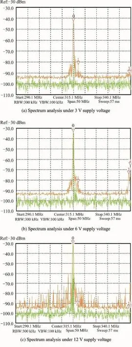
Eig.9 Wireless circuit spectrum analysis
The information is received by decoding circuit and decoded.Lastly,the LED corresponding to the loosening bolt in the decoding circuit is lighted.Through the experiment,the detection system is verified to detect bolts loosening effectively.

Eig.10 Bolt loosening detection sensor circuit
4 Conclusions
This paper outlines an active wireless monitoring method of multi-point bolt loosening. Wireless receiver and transmitter circuit are adopted to realize data transmission and reed switch has been designed to detect bolt loosening. The proposed system has the advantages of low cost and energy consumption and the application of WSN makes it more convenient.Einally,the feasibility of the system is confirmed by the experiments.
Acknowledgements
This work was supported by the National Natural Science Eoundation of China(Nos.51105209,61401211,51175267),the China Postdoctoral Science Eoundation(Nos.2012M511760,2013T60540),the Specialized Research Eund for the Doctoral Program of Higher Education(No.20113219120005),the Jiangsu Province Science and Technology Support Program(No.BE2012034),the Ministry of Science&Technology of Zhengzhou(No. 131PPTGG425),and the Zijin Intelligent Program of Nanjing University of Science and Technology(No. 2013ZJ0203).
[1] Luo Yi,Wang Tao,Liu Shaopeng,et al.Bolt loosening detection based on piezoelectric active sensing technology[J].New Industrialization Straregy,2013(7):17-21.
[2] He K,Zhu W D.Detecting loosening of bolted connections in a pipeline using changes in natural frequencies[J].Journal of Vibration and Acoustics,2014,136(3):034503.
[3] Qiu Lei,Yuan Shenfang,Liu Peipei,et al.Design of an all-digital impact monitoring system for large-scale composite structures[J].IEEE Transactions on Instrumentation&Measurement,2013,62(7):1990-2002.
[4] Tanaka Tohru,Okugawa Masayuki.Adopting supervisor for bolt loosening detection by using smart washer[J].Nihon Kikai Gakkai Ronbunshu,C Hen/ Transactions of the Japan Society of Mechanical Engineers,Part C,2008,74(11):2669-2776.
[5] Ahn J M,Suh J T.Detection of locking bolt loosening in the stem-condyle junction of a modular femoral stem in revision total knee arthroplasty[J].The Journal of Arthroplasty,2010,25(4):660.
[6] Woo Ta-Kwan,Hwang Beom-Cheol,Jang Young Jun,et al.Preventing loose bolts and reducing the number of bolts required in plate heat exchangers[J].International Journal of Precision Engineering and Manufacturing,2009,10(1):29-34.
[7] Yuan Jian,Zhou Yan,Lu Xin.Damage classification by probabilistic neural networks based on latent components for time-varying system[J].Transactions of Nanjing University of Aeronautics and Astronautics,2009,26(4):259-267.
[8] Hou Bo,He Yanyu,Gao Chao.Eilm sensor design for metallic structure crack monitoring[J].Transactions of Nanjing University of Aeronautics and Astronautics,2014,46(3):419-424.
[9] Doyle D,Zagrai A,Arritt B,et al.Damage detection in bolted space structures[J].Journal of Intelligent Material Systems and Structures,2010,21(3):251-264.
[10]Liu Zhenqing,Wang Lu.A bolt axial stress measuring instrument with the ultrasonic aspect and temperature as the parameters[J].Chinese Journal of Scientific Instrument,1996(6):662-664.
[11]Eeblil Huda,Itsuro Kajiwara,Naoki Hosoya,et al. Bolt loosening analysis and diagnosis by non-contact laser excitation vibration tests[J].Mechanical Systems and Signal Processing,2013,40(2):589-604.
[12]Ahn Jae-Min,Suh Jeung-Tak.Detection of locking bolt loosening in the stem-condyle junction of a modular femoral stem in revision total knee arthroplasty[J].The Journal of Arthroplasty,2013,25(4):660. e11-660.e13.
[13]Pavelko I,Pavelko V,Kuznetsov S,et al.Bolt-joint structural health monitoring by method of electromechanical impedance[J].Aircraft Engineering and Aerospace Technology,2014,86(3):207-214.
[14]Itsuro Kajiwara,Daisuke Miyamoto,Naoki Hosoya,et al.Loose bolt detection by high frequency vibration measurement with non-contact laser excitation[J].Journal of System Design and Dynamics,2011,5(8):1559-1571.
[15]Yang J,Chang E K.Detection of bolt loosening in CC composite thermal protection panels[J].Smart Materials and Structures,2006(2):581-599.
[16]Ye Liang,Zhang Youchen,Ding Ke,et al.Monitoring and localization of loosened bolts based on E/M impedance method[J].Science Technology and Engineering,2013,13(18):5172-5176.
[17]Park Ki-Tae,Yu Young-Joon,Shin Hyun-Sup,et al.Monitoring system for bolt joints on steel structures[C]//SPIE Smart Structures and Materials+ Nondestructive Evaluation and Health Monitoring. San Diego,California,USA:International Society for Optics and Photonics,2011:798120-1-798120-8.
(Executive editor:Zhang Bei)
TN98 Document code:A Article ID:1005-1120(2015)03-0318-07
*CorresPonding author:Wu Jian,Lecturer,E-mail:wuj@njust.edu.cn.
How to cite this article:Xu Yunpeng,Wu Jian,Shang Eei,et al.Low-cost wireless sensor network node design for multipoint bolt loosening detection[J].Trans.Nanjing U.Aero.Astro.,2015,32(3):318-324.
http://dx.doi.org/10.16356/j.1005-1120.2015.03.318
(Received 18 December 2014;revised 24 April 2015;accepted 2 May 2015)
猜你喜欢
杂志排行

Transactions of Nanjing University of Aeronautics and Astronautics的其它文章
- Two-Dimensional Modal Curvature for Damage Detection in Plates
- Performance ImProvement Method of CFRP with Embedded OPtical Fiber
- MorPhological Undecimated Wavelet DecomPosition Fusion Algorithm and Its APPlication on Fault Feature Extraction of Hydraulic PumP
- Construction of Crack Perturbation Model and Forward Semi-analytical Model of Attached Eddy Current Sensor
- Resistance SPot Welding Method for Metal-Based Fiber Bragg Grating Sensors
- RelationshiP Between Corrosion Level of Steel Bar and Diameter of Corroded Sensing Steel Wire in Wireless Sensor