Stress-strain characteristics of linear friction welding of TC11 and TC17 alloys*
2015-09-05ZhaoPengkangFuLiZhangTiancangZhongDechaoandWangPeiyan赵鹏康张田仓钟德超王佩艳
Zhao Pengkang,Fu Li,Zhang Tiancang,Zhong Dechao and Wang Peiyan赵鹏康,傅 莉,张田仓,钟德超,王佩艳**
Stress-strain characteristics of linear friction welding of TC11 and TC17 alloys*
Zhao Pengkang,Fu Li,Zhang Tiancang,Zhong Dechao and Wang Peiyan
赵鹏康,傅 莉,张田仓,钟德超,王佩艳**
Transient stress and strain fields of dissim ilar titanium alloys(TC11 and TC17)joint during linear friction welding(LFW)were investigated by a two-dimensionalmodelwith ABAQUS/Explicit.The results showed that in the X-axis,themaximum compressive stressof850MPa occurred in the center zoneof friction interface,and themaximum tensile stressof 190MPa distributed at the flash;in the Y-axis,themaximum compressive stress of 1 261MPa located at the junction region between thewelding fixture and edge of thespecimen,and themaximum tensilestressof320MPa distributed in the connecting portion between the flash and edge of the specimen.In addition,areas of plastic strain increased gradually during welding process.In the X-axis,tensile strainmainly existed at the heads of the specimens;in the Y-axis,compressive strain mainly occurred at the heads of the specimens.
linear friction welding,TC11/TC17 titanium alloys joint,stress and strain fields
0 Introduction
Friction welding is a solid state process for joining materials through intimate contact of a plastic interface,which is generated by frictional heat produced as one component ismoved relatively to another under pressure[1-3]. Linear friction welding(LFW)is a complicated and quick thermo-mechanically coupled physical process,which is suitable for joiningmaterials with low thermal conductivity and high temperaturemechanical properties[1].Therefore,this process is considered to be particularly appropriate for joining of titanium and nickel alloys[4-8].
Transient stress and strain fields have a great effect on the microstructure evolution and mechanical properties of the welded joints[9-12].However,themeasurements of stress and strain fields are considerably difficult and expensive in the welding process.With the development of computer technology and numerical analysis,simulation has become a powerful and reliable technique for prediction of atomic diffusion,temperature field,stress and strain fields within the welded joint.The atomic diffusion and temperature field of LFW process have been studied through finite element method[13-19].Nevertheless,there are few reports on the plastic stress and plastic strain of LFW.In this study,we investigated transient stress and strain fields of dissimilar titanium alloys joint during LFW by a two-dimensional model with commercial software ABAQUS/Explicit.
1 Num ericalm odeling
1.1Finite elementmodel
A two-dimensional model with two specimens was built to simulate the plastic stress and strain trends during LFW process by using ABAQUS/Explicit.During welding process,the mesh distortion near interface is serious be-cause of severe joint deformation.Therefore,the specimen was partitioned into two regions,where near interface of 20mm has a meshing size of 1mm×1 mm and the other 110mm region has a gradually increasing meshing size. Themesh is conducted using a 4-node quad elementwith coupled displacement and temperature,reduced integration and hourglass control.The Arbitrary Lagrangian Eulerian adaptive mesh control was used to reduce the mesh distortion and improve calculation efficiency.The specimens used in the simulation and experiment are both blockswith dimensions of 130mm×75 mm×20 mm.In the model,the 110mm clamped zone was only allowed to move in the Y-direction and fixed in X-direction of the upper specimen.The lower specimen was allowed tomove in the X-direction in a sinusoidalmode with a given amplitude and frequency.The initial temperature of the specimen was set at room temperature(30℃).The welding parameters used formodeling are as follows,the oscillation frequency,amplitude of oscillation,friction pressure,forging pressure,welding time and forging time are 40 Hz,3mm,50MPa,75MPa,3.6 s and 10 s,respectively.
1.2Material properties
The welded materials used in the simulation are TC11 (Ti-6.5Al-3.5Mo-1.5Zr-0.3Si)and TC17(Ti-4Mo-4Cr-5Al-2Sn-2Zr)alloys.They areα+βtype titanium alloys. During LFW process,the plastic deformation is much greater than the elastic deformation.Therefore,the rigidity-plastic constitutive law can be used for the LFW process[8].By thismethod,the computation process was simplified and the efficiency was highly elevated with little computation precision loss.The theoretic base of the ideal rigidity-plastic model is Markov variation principle,and without considering thematerial hardening in the deformation process.The constitutive law can be expressed as follows,
1.3Heat flow m odel
During LFW process,the friction heat power is produced by the relativemovement of specimens on the welding interface.The average heat rate can be deducted as follows[16],
whereμ,α,PNand f are coefficient,amplitude,pressure and oscillation frequency of friction.According to reference[18],the fraction of frictionally dissipated energy converted into heat is about 90%.The weight factor for the distribution of heat hdf between two contact surfaces is calculated for dissimilarmaterials as follows,

where,λis thermal conductivity,ρis density and cPis specific heat.The indices 1 and 2 denote thematerial of parts to be welded.The total heat is the sum of both factors q=q1+q2.For identicalmaterials,the heat is distributed equally.Since material properties of TC11 and TC17 alloy are very close,therefore,half of the total heat is allotted to the specimen.
2 Results and discussion
Fig.1 and Fig.2 showed the distribution of plastic stress in X-axis and Y-axis.It can be observed that compressive stressesmainly occurred in themiddle portion of friction interface and tensile stresses distributed near the flash.In X-axis,areas of the compressive stress enlarged gradually and zones of tensile stress reduced during welding process.Themaximum compressive stress of 770MPa located at the middle of friction interface near TC17 side and the maximum tensile stress of 100 MPa distributed near the flash during the friction phases.Furthermore,the maximum compressive and tensile stresses rose to 850MPa and 190MPa respectively during the forging phase.In addition,it can be found that the amount and size of com-pressive stress zone of TC17 alloy are obviously greater than that of TC11 alloy.Since the strength of TC17 alloy is higher than that of TC11 alloy,the specimen deformation of TC17 alloy would need more energy in the forging phase,which leaded tomore residual stress on TC17 alloy side.As shown in Fig.2,in the Y-axis,the maximum compressive stress of 790 MPa distributed at the junction region between the welding fixture and edge of the specimen,and maximum tensile stress of 160 MPa occurred in the connecting portion between the flash and edge of specimens during the friction phases.In the forging phase,the maximum compressive and tensile stresses rose to 1 261 MPa and 320 MPa respectively due to larger forging force applied in the sample after vibration.Therefore,the deformation zone in the specimen stored more residual stresses.
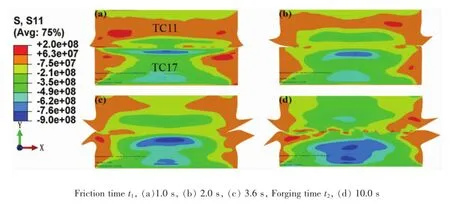
Fig.1 Distribution of X-axis stress
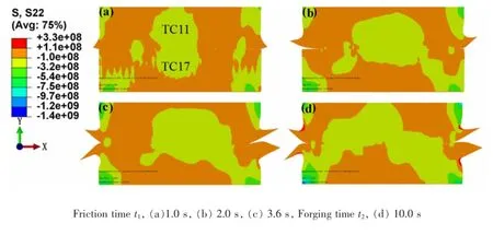
Fig.2 Distribution of Y-axis stress
Strain fields of friction interface were also studied. Fig.3 and Fig.4 showed the plastic strain distribution along the X-axis and Y-axis during the friction and forging phases.It can be seen from Fig.3 that areas of plastic strain increased gradually during welding process.Along the X-axis direction,strains of the specimen were mainly tensile because tensile stresses exist near the flash,and that leaded to the plasticmetalmove from the center zone to edge.In the Y-axis,strains of the specimen weremainly compressive,which extruded plastic metal to interface. Meanwhile,the maximum strain zone occurred near the flash and little plastic strain distributed at the center zoneof the friction interface.The reason for thiswas that lots of plastic metal were extruded to edge of the specimen from interface center by friction pressure and shear force during welding process.
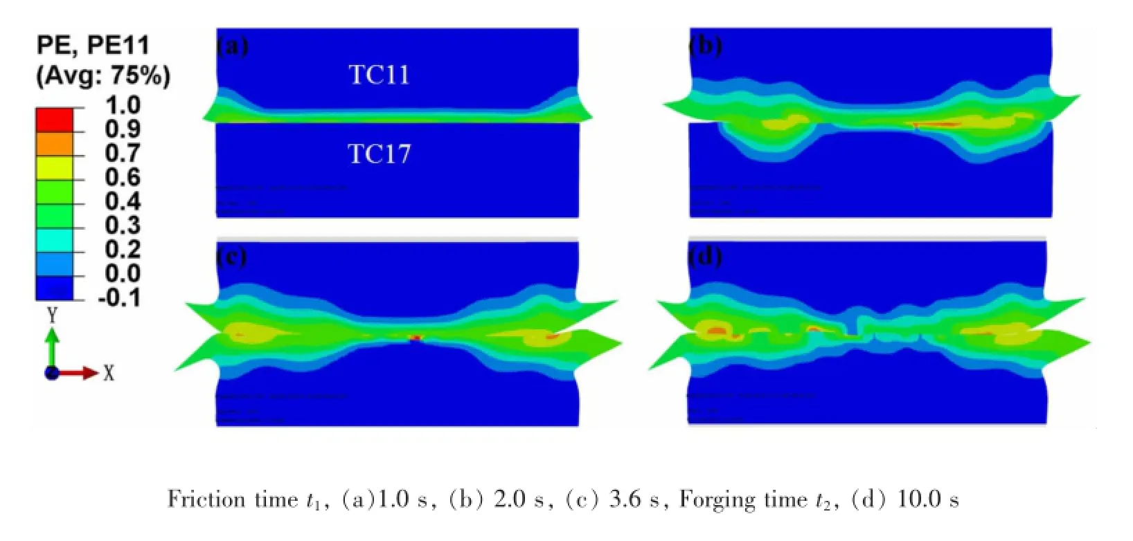
Fig.3 Distribution of X-axis strain

Fig.4 Distribution of Y-axis strain
3 Conclusions
(1)Along the X-axis,the maximum compressive stress of850MPa occurred in the center zone of friction interface,and the maximum tensile stress of 190 MPa distributed near the flash;along the Y-axis,the maximum compressive stress of 1 261MPa located at the junction region between the welding fixture and edge of the specimen,and themaximum tensile stress of 320MPa distributed in the connecting portion between the flash and edge of specimen.
(2)Areas of plastic strain increased gradually during welding process.Strains of the specimen were mainly tensile along the X-axis,but compressive along the Y-axis.
References
[1] Vairis A,FrostM.High frequency linear friction weldingofa titanium alloy.Wear,1998,217:117-131.
[2] Crosslan B.Friction welding.Contemporary Physics,1971,12:559-574.
[3] Romero J,Attallah M M,Preuss M,et al.Effect of the forging pressure on themicrostructure and residual stress development in Ti-6Al-4V linear friction welds.Acta Materialia,2009,57:5582-5592.
[4] Wanjara P,Jahazi M.Linear friction welding of Ti-6Al-4V:processing,microstructure,andmechanical-property inter-relationships.Metallurgical and Materials Transactions A,2005,36A:2149-2164.
[5] Mohandas T,Banerjee D,Kutumba Rao V V.Microstructure and mechanical properties of friction welds of anα+βtitanium alloy.Materials Science and Engineering:A,2000,289:70-82.
[6] Baeslack IIIW A,Broderick TF,JuhasM,etal.Characterization of solid-phase welds between Ti-6A1-2Sn-4Zr-2Mo-0.1Si and Ti-13.5A1-21.5Nb titanium aluminide.Materials Characterization,1994,33:357-367.
[7] Bhamji I,PreussM,Threadgill PL,etal.Solid state joining ofmetals by linear friction welding:a literature review.Materials Science and Technology,2011,27:2-12.
[8] Tao J,Zhang TC,Liu PT,etal.Numerical computation of a linear friction welding process.Materials Science Forum,2008,575:811-815.
[9] Chang B H,Shi Y W,Dong S J.Studies on a computational model and the stress field characteristics of weld-bonded joints for a car body steel sheet.Journal of Materials Processing Technology,2000,100:171-178.
[10] Prime M B,Gnäupel-Herold T,Baumann JA,etal.Residual stressmeasurements in a thick,dissimilar aluminum alloy friction stir weld.Acta Materialia,2006,54:4013-4021.
[11] Genevois C,Deschamps A,Denquin A,et al.Quantitative investigation of precipitation and mechanical behaviour for AA2024 friction stir welds.Acta Materialia,2005,53: 2447-2458.
[12] Preston R V,Shercliff H R,W ithers P J,et al.Physicallybased constitutive modelling of residual stress development in welding of aluminium alloy 2024.Acta Materialia,2004,52:4973-4983.
[13] Zhao P K,Fu L,Zhong D C.Numerical simulation of transient temperature and axial deformation during linear friction welding between TC11 and TC17 titanium alloys.Computational Materials Science,2014,92:325-333.
[14] Song C,Lin T,He P,et al.Molecular dynamics simulation of linear friction welding between dissimilar Ti-based alloys. Computational Materials Science,2014,83:35-38.
[15] Jiao Z,Song C,Lin T,et al.Molecular dynam ics simulation of the effect of surface roughness and pore on linear friction welding between Ni and Al.Computational Materials Science,2011,50:3385-3389.
[16] Vairis A,Frost M.Modelling the linear friction welding of titanium blocks.Materials Science and Engineering:A,2000,292:8-17.
[17] Li W Y,Ma T J,Li J L.Numerical simulation of linear friction welding of titanium alloy:effects of processing parameters.Materials&Design,2010,31:1497-1507.
[18] Sorina-Müller J,Rettenmayr M,Schneefeld D,et al.FEM simulation of the linear friction welding of titanium alloys. Computational Materials Science,2010,48:749-758.
[19] Turner R,Gebelin JC,Ward R M,et al.Linear friction welding of Ti-6Al-4V:modelling and validation.Acta Materialia,2011,59:3792-3803.
*Thiswork was supported by Programme of Introducing Talents of Discipline to Universities(No.B08040),Innovation Project of Shaanxi Province Overall Plan on Science and Technology(No.2012HBSZS021)and Project of Key Areas of Innovation Team in Shaanxi Province (No.2014KCT-12).
**Zhao Pengkang,Fu Li,Zhong Dechao,State Key Laboratory of Solidification Processing,Shaanxi Key Laboratory of Friction Welding Technologies,Northwestern Polytechnical University,Xi'an,710072. Zhang Tiancang,Beijing Aeronautical Manufacturing Technology Research Institute,Beijing,100024. Wang Peiyan,Civil Engineering and Architecture,Northwestern Polytechnical University,Xi'an,710129. Fu Li,Corresponding author,E-mail:fuli@nwpu.edu.cn
杂志排行
China Welding的其它文章
- A Fe-Ni-Cr system filler metal for brazing of stainless steel*
- Numerical analysis of thermal process in continuous drive radial friction welding*
- Effect of refilling time on Microstructure and Mechanical properties of friction spot welded LY12 alum inum alloy*
- Simulation of phased array S-scan acoustic field in FSW joint of alum inum alloy extrudate w ith com p lex shape*
- Mechanical and corrosion properties of 445J2 ultra pure ferritic stainless steel joint*
- Simulation on the deformation controlling of T-joint LBW w ith auxiliary heat source for high strength alum inum alloy*