Hypersonic sliding target tracking in near space
2015-07-02XingyuZHANGGuohongWANGZhenyuSONGJiojioGUInstituteofInformtionFusionNAAUYnti264001ChinDeprtmentofScientificReserchNAAUYnti264001Chin
Xing-yu ZHANG*, Guo-hong WANG Zhen-yu SONG, Jio-jio GUInstitute of Informtion Fusion, NAAU, Ynti 264001, ChinDeprtment of Scientific Reserch, NAAU, Ynti 264001, Chin
Hypersonic sliding target tracking in near space
Xiang-yu ZHANGa,*, Guo-hong WANGa, Zhen-yu SONGb, Jiao-jiao GU
aaInstitute of Information Fusion, NAAU, Yantai 264001, ChinabDepartment of Scientific Research, NAAU, Yantai 264001, China
Received 4 March 2015; accepted 13 May 2015 Available online 14 June 2015
Abstract
To improve the tracking accuracy of hypersonic sliding target in near space, the influence of target hypersonic movement on radar detection and tracking is analyzed, and an IMM tracking algorithm is proposed based on radial velocity compensating and cancellation processing of high dynamic biases under the earth centered earth fixed (ECEF) coordinate. Based on the analysis of effect of target hypersonic movement, a measurement model is constructed to reduce the filter divergence which is caused by the model mismatch. The high dynamic biases due to the target hypersonic movement are approximately compensated through radial velocity estimation to achieve the hypersonic target tracking at low systematic biases in near space. The high dynamic biases are further eliminated by the cancellation processing of different radars, in which the track association problem can be solved when the dynamic biases are low. An IMM algorithm based on constant acceleration (CA), constant turning (CT) and Singer models is used to achieve the hypersonic sliding target tracking in near space. Simulation results show that the target tracking in near space can be achieved more effectively by using the proposed algorithm.
Copyright©2015, China Ordnance Society. Production and hosting by Elsevier B.V. All rights reserved.
Keywords:Near space; Hypersonic velocity; High dynamic bias; Tracking; Maneuvering
E-mail address: zxy627289467@sina.com (X.Y. ZHANG).
Peer review under responsibility of China Ordnance Society.
http://dx.doi.org/10.1016/j.dt.2015.05.004
2214-9147/Copyright©2015, China Ordnance Society. Production and hosting by Elsevier B.V. All rights reserved.
1. Introduction
In recent years, with the continuously appearing of near space hypersonic vehicles, such as X-43 [1] and X-51A [2], the defense against rapid strike weapons has become an urgent problem to be solved. The near space target is different from the traditional aerodynamic target [3] and the satellite orbital target [4]. It has its unique hypersonic sliding trajectory [5], and can rapidly attack any target in the world in two hours, but the existing warning defense system is unable to track and intercept the threat target effectively. Therefore, it is necessary to research the tracking of hypersonic sliding target in near space.
The domestic & foreign researches have been still in the primary stage for the study of target tracking in near space. The target trajectory, from launch to impact, is divided into three major phases [6]: boost, coast, and reentry. The boost phase of motion, which lasts from launch to thrust burnout, was discussed in Ref. [7] where the vehicle is accelerated to the designed altitude and velocity for beginning a sliding trajectory. The coast phase, sustaining the motion of skidding to the desired range, was analyzed in Ref. [8]. And the reentry phase, beginning when the sustaining burns are discontinued, was discussed with the state augment tracking methods in Ref. [9].
In view of the tracking of this sliding trajectory target, a modified constant turning (MCT) model was proposed to enhance the performance of tracking high maneuvering target [10]. A variable structure multiple model tracking algorithm based on the directed graph (DG-VSMM) was proposed to further overcome the weakness of maneuvering target tracking with the single model [11]. And in Refs. [12,13], the IMM tracking algorithm is considered one of the most dependable methods in the field, and the robust tracking can be achieved through the interaction among different models.
However, all the researches above are based on the analysis of target maneuvering, but have not considered the influence of target hypersonic velocity. Nevertheless, the target in near space moves at a hypersonic velocity, and the hypersonic velocity makes a great difference on radar detection and tracking.
From Ref. [14] we know that the linear frequency modulated (LFM) signal is one of the most famous radar signals, which is of large time-bandwidth product, and can significantly improve the signal-to-noise (S/N) ratio when the matching filter is performed. But the disadvantage of this signal is that it is not sensitive to the Doppler shifts [15]. While the Doppler shifts exist as the target moves at a radial velocity. That is to say, the radar detection and tracking are inevitably affected by the radial velocity. In the case of low radial velocity, this property from target echo can be approximately neglected. But when the target moves at a hypersonic velocity, the effect of Doppler shift on the target tracking has not been discussed for hypersonic movement of the target, and a solving method has not been mentioned yet in the existing references.
In this paper, we firstly analyze the influence of target hypersonic movement on radar detection and tracking. Then the measurement models of hypersonic sliding target tracking in near space are established, and the high dynamic biases which are caused by the target hypersonic movement are eliminated through the radial velocity estimation and the cancellation processing method. Finally, an IMM tracking algorithm based on the CA, CT, and Singer models are utilized to further achieve the tracking of hypersonic sliding target in near space.
2. Influence of target hypersonic movement on radar measurements
Since the LFM signal is one of the most famous radar signals, which is of large time-bandwidth product, and can significantly improve S/N ratio when the matching filter is performed. The PC (pulse compression) radar which emits LFM signal) is selected to discuss the problem of hypersonic target tracking in near space.
We assume that the PC radar emits the LFM signalwhere rect(k/τ)= 1,|k|≤(1/2)τ,τ is the emitting pulse width, f0is the central carrier frequency,μ= B/τ is the FM rate, B is the FM band width.

When the target moves at a radial speed of v, the received signal at time k can be expressed as followswhere t0=(2R0/c), R0is the target distance at time t0, c is the light speed,γ= 1 +(2v/c).

At this time, if the matched filtering technique is used to the received signal sr(k), the output of the matching filters can be expressed as

where fd=(2v/c)f0is the target Doppler shift. Then according to the maximum signal-to-noise ratio criterion, the signal so(k)has a maximum value at time k = t0±(fd/μ). That is to say, the radar measurements are inevitably affected by the following dynamic biases

In order to evaluate the influence of target hypersonic movement on the tracking of near space target, the relative analysis is as follows.
1) When the target moves at a hypersonic velocity, the high dynamic biases will be brought into the radar measurements of the near space target. For example, when the target in Fig. 1 moves at a constant velocity of V = 5 km/s and the motion direction relative to the radar is ψk= 10°, the target distance and attitude are rk= 600 km and hk= 20 km, respectively, the radar wavelength is λ= 0.15 m, and the pulse width and band width of the linear FM signal are τ= 600 μs and B = 1.5 MHz, respectively, the high dynamic biases caused by the target hypersonic movement can reach to

while the measurement errors of the conventional radar are 100m around. That is to say, the high dynamic biases, which seriously affect the tracking of near space target, can not be neglected.2) It can be seen from Eq. (4) that the high dynamic bias Δr, which is different from the random measurement errors, varies with the specific parameters of the PC radar, such as radar wavelength λ, pulse width τ and band width B). 3) From Eq. (4), we see that the high dynamic bias Δr, which is caused by the target hypersonic movement, is proportional to the radial velocity v. The high dynamic bias Δr increase with the increase in radial velocity v when the radar parameters remain unchanged. 4) From Fig. 1 and Eq. (5), we see that the high dynamic bias Δr is also affected by the motion direction ψk, the target distance rkand the target attitude hk. And the influence of motion direction ψkis much larger than the other ones. This is because when the value of ψkis lager, cos ψk≈0, the high dynamic bias Δr can be approximately regarded as nonexistence. When the value of ψkis lower, Δrk≈(2τc/Bλ)V (rk≫hk), the high dynamic bias Δr makes a great difference on near space target tracking.
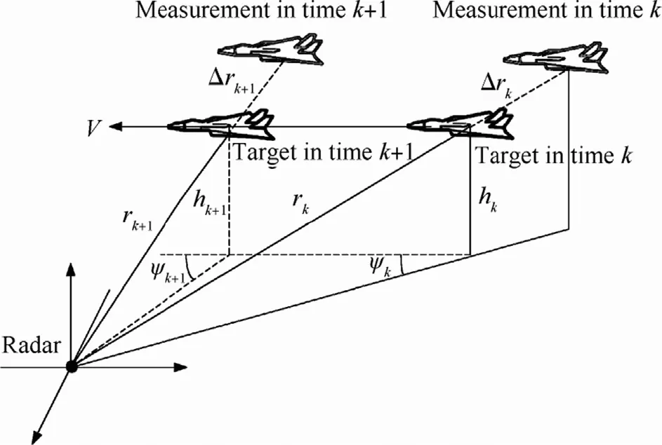
Fig. 1. Measurement with high dynamic biases of near space target.
3. Tracking models of hypersonic sliding target in near space
3.1. Measurement transformation
From the analysis above, we know that the high dynamic biases are brought into the radar measurements when the target moves at a hypersonic velocity. In this case, the robust tracking of near space target is unable to be achieved by single radar, so the radar network systems under the ECEF coordinate are utilized to overcome the problem here.
We assume that the same target in near space is tracked by radar A and B at different sites. The measurement of radar i(i = A,B)at time k is constructed by the slant range ri(k), the azimuth θi(k)and the elevation φi(k). The measurement is affect by the high dynamic biases above, and is given by

where Δri(k)is the high dynamic bias from Eq. (4), [r(k),θ(k),φ(k)]is the true value of target measurement,[δri(k),δθi(k),δφi(k)]Tis the measurement noise which distributes the zero-mean white with covariance matrix Rδi= diag[σ2riσ2θiσ2φi].
Since the influence of measurement errors can be weakened by unbiased conversion [16], the target measurement under the north east down (NED) coordinate is given by

where λθi= e-σ2θi/2,λφi= e-σ2φi/2.
The measurement under the selected ECEF coordinate can further be written as


where is the orientation matrix,[Li(k),Bi(k),hi(k)]is the geodetic coordinateofradar,ZiECEF(k)andZiECEF_O(k)arethemeasurements of target and radar under the ECEF coordinate, respectively. 3.2. Measurement model with high dynamic biases
Assuming that the state vector of near space target under the ECEF coordinate at time k is
XECEF(k)=[x(k).x(k)¨x(k)y(k).y(k)¨y(k)z(k).z(k)¨z(k)]T(10)
When the influence of target hypersonic movement is not considered, the discrete state equation and measurement equation are given bywhere Φ(k)is the state transition matrix, H(k)is the measurement matrix, VECEF(k)and WiECEF(k)are the process noise and measurement noise, respectively.


However, from Eqs. (6)-(8) we see that, when the target moves at a hypersonic velocity, the high dynamic bias is

where ZECEF(k)is the true value of the target under the ECEF coordinate.
In this case, if the measurement equation in Eq. (12) is still used in the tracking of hypersonic target, a remarkable
deviation exists under the influence of high dynamic biases. Thus, considering the influence of target hypersonic movement on radar detection and tracking, the measurement equation is modified as


where is the coefficient matrix of Δr(k).
3.3. Influence of high dynamic biases on multi-radar
data association
Based on the modification of measurement equation, Radar A and B at different sites are utilized to eliminate the influence of high dynamic biases cooperatively. In this case, we must firstly determine which measurements from different radars represent the same target. This determination is known as data association. (This data association criterion is not the emphasis of this paper, and can be seen in Ref. [17].)
In the condition of the correct association of different radar measurements, we can have (see Eq. (13))
where ZECEF(k)is the true value of near space target under the ECEF coordinate.
Eliminating the true values in Eq. (16), we can haveEq. (17) can be rewritten as

It can be seen from Eq. (18) that, when the value of Δri(k)is low enough,

The test statistics (see Ref. [17])

approximately submits to the chi-square distribution with 3 degrees of freedom. In this case, the influence of high dynamic biasΔri(k)on the association of different radar measurements can be ignored.
On the contrary, when the value of Δri(k)is much larger, there is a significant difference between the measurements of Radar A and B as follows

Thus, the test statistics η2(k)submits to the non-central chisquare distribution with 3 degrees of freedom and non-central parameter δ(k).


Obviously, the test statistics η2(k)in Eq. (22) is not suitable for the existing chi-square statistic criterion in Ref. [17]. And from Fig. 2, we see that a large probability of false association is produced when the existing chi-square statistic criterion is directly used.
3.4. The cancellation processing based on radialvelocity estimation
In view of this situation, the radial velocity measurement .ri(k)is brought into Eq. (14), and the high dynamic bias Δri(k)is compensated by Eq. (4). Thus the problem of target tracking with high dynamic biases is transformed to the one with lower dynamic biases.
We assume thatˆv(k)is the estimation of radial velocity measurement .ri(k)during the target tracking. Then the high dynamic bias Δri(k)in Eq. (4) can be approximately obtained by

where

The measurement equation in Eq. (14) can be modified by

whereˆZiECEF(k + 1)is the compensated target measurement,
Δ~ri(k)is the lower dynamic bias which is compensated by the radial velocity estimation, and


Fig. 2. Non-central chi-squared PDF.

It can be seen from Eq. (28) that a much lower dynamic bias Δ~ri(k)can be obtained with the compensation of radial velocity estimation. In this case, from Eqs. (18)-(20) we know that the correct association of different radar measurements can be performed successfully.
Based on the correct association of different radar measurements, a cancellation equation is established to eliminate the influence of high dynamic biases. We assume that, in the condition of time synchronization, the modified measurement equation of Radar A and B are given bywhere ΔˆrA(k)and ΔˆrB(k)are the compensated lower dynamic biases of Radar A and B, CA(k)and CB(k)are the coefficient matrixes of ΔˆrA(k)and ΔˆrB(k), respectively.


Subtracting Eq. (31) from Eq. (30) yields

Adding Eqs. (30) and (31) together yields

Substituting Eq. (33) into Eq. (32), we can get the following cancellation equation which is merely related to the target state

where

3.5. Measurement model analysis
As seen in Eq. (34), the influence of high dynamic biases on target tracking can be eliminated effectively by the cancellation equation when the measurements from different radars are associated correctly. An important question is proposed in which the compensated measurement~ZiECEF(k)in Eq. (34) canbe replaced by ZiECEF(k)with lower random measurement errors.
Since the cancellation equation above is established on the assumption of time synchronization, the time alignment must be performed firstly if the measurement ZiECEF(k)is directly used to eliminate the high dynamic biases. The interpolation/ extrapolation algorithm is taken as an example, and the measurements ZBECEF(kB)and~ZBECEF(kB)of Radar B at time kBare aligned to the time kAof Radar A

Substituting Eqs. (4), (13), and (27) into Eq. (36) yields■■

where ZEACBEF(kA)andZ~AECBEF(kA)are the time alignment mea
surements of ZEBCEF(kB)andZ~BECEF(kB), respectively, ZECEF(kA)is the true value of the target measurement at time kA,ΔBECEF(kB)is the high dynamic bias at time kB,ΔAECBEF(kA)is the time alignment bias at time kA, and

where TBis the sampling time of Radar B, kAand kBare the time nodes of the measurements of Radar A and B, respectively.
From Eq. (37) we see that the time alignment measurement ZEACBEF(kA)is additionally impacted by the high dynamic bias ΔBECEF(kB)and the time alignment bias ΔAECBEF(kA)compared with the compensated measurement Z~AECB
EF(kA). In this case, if the uncompensated measurement ZEiCEF(k)is used to establish the cancellation equation directly, the result leads to the significant errors which affect the target tracking seriously. Therefore, the cancellation equation must be established by the compensated measurementZ~iECEF(k).
3.6. IMM tracking
3.6.1. Model selecting
Considering the complexity of target trajectory, the CA, CT, and Singer models are selected as the sub-models of IMM to achieve the tracking of hypersonic sliding target in near space. The model selecting is organized as follows.
First of all, Singer model is chosen as the chief model of the IMM tracking. It is a typical global statistic model which not only considers the whole possibility of target maneuvering motion, but also balances the precision of the nonmaneuvering model. Then CA model is used to further improve the tracking accuracy of Singer model. This is because the trajectory of near space target can be also approximately regarded as a combination of multiple trajectories with constant acceleration when the sampling time is short enough. Finally, CT model is used to make up for the weakness of Singer model in tracking of strong maneuvering target.
3.6.2. Sub-model filtering with cancellation equation
In the condition of the reasonable selection of each submodel, the sub-model is combined with the cancellation measurement equation above to further achieve the tracking of hypersonic sliding target in near space.
We assume that the input state vector and its covariance of sub-mode lj(j = 1, 2, 3) at time k are XECEF (k|k) and PECEF(k|k), respectively. Then we construct the predicted vector and its covariance to further remove the influence of high dynamic biases


It can be seen from Eq. (39) that the predicted vector is equivalent to the originally predicted vector XojECEF(k + 1|k), so the predicted measurement is given byMeanwhile, we get the cancellation measurement from Eq. (38) as follows


The measurement residual and the residual covariance are given by

And the filter gain is given by


Thus the output state and its covariance of sub-model j are updated by


3.6.3. Model interaction
In the condition of the implementation of each submodel filtering with cancellation equation, the IMM algorithm in Ref. [18] is used to obtain the optimal state estimate of hypersonic sliding target in near space. The architecture of the IMM algorithm is illustrated in Fig. 3. The complete recursion of the IMM algorithm is seen in Ref. [18].
4. Simulation
Computer simulation is used to study the performance of the proposed tracking algorithm, and four methods in Section 4.1 are compared with the proposed method in this paper.

Fig. 3. The architecture of IMM algorithm.
4.1. Scenario
In this section, the target trajectory is built in the geodetic coordinate, the measurements are obtained in the polar coordinate of the radar, and the tracking of near space target is achieved in the ECEF coordinate.
1) Trajectory building
In the scenario, the trajectory of near space target is built according to the S-trajectory (Sanger trajectory) [19]. And in the S-trajectory, the target moves at a hypersonic velocity owing to the composite forces of thrust, lift, drag, and gravity. The implementation of the trajectory building can be seen in Ref. [20].
Assuming that the initial position of target is given by [N30°,E130°,16 km]with an initial speed of 5 Ma. At the initial time, the mass of target is 3600 kg, the angle-ofattack is 1°, and the heading angle and the flight path angle is 260°and 0°, respectively. In the simulation conditions above, the hypersonic sliding trajectory in near space is given in Fig. 4.
2) Radar measurements
The near space target is tracked by Radar A and B at different sites. The positions of two radars are [N33°,E130.5°,0 km]and[N37°,E130.5°,0 km], respectively.

Fig. 4. Target trajectory in near space under the geodetic coordinate.
Both Radar A and B have the same parameters. The radar wavelength is 0.15 m, the pulse signal width and the bandwidth are 600 μs and 1.5 MHz, respectively. The measurement errors of slant range, azimuth angle, elevation angle and velocity are 100 m, 0.2°, 0.2°, and 100 m/s, respectively. The sampling period is 0.05 s.
4.2. Simulation results and discussion
4.2.1. Example 1
To analyze the effect of target hypersonic movement on near space target tracking, the proposed method is compared with the IMM tracking algorithm in Ref. [8].

Fig. 7. Probability of correct association for different tracking algorithms.
Fig. 5 shows the trajectory and tracking results of the hypersonic sliding target in near space. To simplify the analysis, only the duration of(0,50s)is allowed here. From Fig. 5 we see that the target state estimation leads to a remarkable deviation under the influence of high dynamic biases, while the proposed method can solve the problem better.
Fig. 6 shows the target state estimate errors of different tracking algorithms. The proposed method has smaller position estimate error and faster convergence rate compared to the IMM tracking algorithm in Ref. [8] (see Fig. 6(a)), and the position estimate error of the proposed method is decreased by 1500 m after the compensation of high dynamic biases. It can be seen form Fig. 6(b) and (c) that there is little difference on velocity estimation and acceleration estimation between the two methods.
Therefore, target hypersonic movement has a great difference on the position estimate, but has little influence on velocity estimation and acceleration estimation.
4.2.2. Example 2
To analyze the necessity of measurement compensation by radial velocity estimation, the proposed method is compared with the tracking algorithm in Ref. [21] in the case of time synchronization.
Fig. 7 shows the probability of correct association for different tracking algorithms. The proposed method has a larger probability of correct association under the influence of high dynamic biases, and the correct association probability can reach to 90%. While the probability of correct association of the tracking algorithm in Ref. [21] is relatively low, and the correct associations of different radars are even unable to be performed at the initial time.
Fig. 8 shows the target state estimate errors for different tracking algorithms. The target state estimate errors of the proposed method are much lower than those of the tracking algorithm in Ref. [21] under the influence of high dynamic biases. And compared with the tracking algorithm in Ref. [21], the proposed method has a great improvement on target position estimation, while the improvements of velocity estimation and acceleration estimation are relatively small.
Therefore, it is necessary to compensate the target measurements by radial velocity estimation in the case of time synchronization.

Fig. 8. Target state estimate errors for different tracking algorithms.

Fig. 9. Time alignment errors for different tracking algorithms.
4.2.3. Example 3
To further analyze the necessity of measurement compensation by radial velocity estimation, the proposed method is compared with the tracking algorithm in Ref. [22] in the case of time non-synchronization. In this example, the sampling time of Radar A and B are 0.1s and 0.15s, respectively.

Fig. 10. Probability of correct association for different tracking algorithms.
Fig. 9 shows the time alignment errors for different tracking algorithms,wherethesamplingtimesof Radar Aand Bareboth aligned to a common interval of 0.05s. Under the influence of high dynamic biases, the time alignment errors of the proposed method are lower than those of the tracking algorithm inRef. [22],and the time alignment errors of the proposedmethod are decreased by approximately 2000 m. Fig. 10 shows the probability of correct association for different tracking algorithms. Under the influence of high dynamic biases, the proposed method has a larger probability of correct association, which is more than 90%. While the correct association probabilityofthetrackingalgorithmin Ref.[22]isrelativelylow,and increases first and then decreases, which is due to the fast changing of radial velocity when the target is close to the radar.
Fig. 11 shows the target state estimate errors for different tracking algorithms. The target state estimate errors of the proposed method are much lower than those of the tracking algorithm in Ref. [22] under the influence of high dynamic biases. It can be seen from Fig. 11 that the proposed method has a great improvement on position estimation especially after the time of 100 s. While the improvement of velocity estimation and acceleration estimation is relatively small.
Therefore, it is necessary to compensate the target measurements by radial velocity estimation in the case of time non-synchronization.
4.2.4. Example 4
To verify the superiority of cancellation processing of high dynamic biases, the proposed method is compared with the all augmented model (AAM) tracking algorithm in Ref. [23].
Fig. 12 shows the target state estimate errors for different tracking algorithms. The position estimate errors of the proposed method are much lower than those of the tracking algorithm in Ref. [23], and the tracking accuracy is increased by about1000mwhenthecancellationprocessingofhighdynamic biases is used. The velocity and acceleration estimate errors of the proposed method are also lower than those of the tracking algorithm in Ref. [23], and there is a great improvement on the tracking stability. This is because the high dynamic biases are consideredtobeconstant bythetrackingalgorithmin Ref.[23], but the high dynamic biases are time-varying in realize, so the velocity and acceleration estimate errors of the tracking algorithm in Ref. [23] inevitably increase.
Hence, compared with the tracking algorithm with the systematic biases, the hypersonic target tracking in near space can be performed more accurately.
4.2.5. Example 5
To verify the superiority of the proposed method, it is compared with the method in Ref. [24].
Fig. 13 shows the target state estimate errors for different tracking algorithms. The position, velocity and acceleration estimate errors of the proposed method are much lower than those of the signal processing method in Ref. [24]. This is because the high dynamic biases can be compensated more accurately with the real-time estimation of radial velocity in the proposed method. While the accuracy of radial velocity estimation of the signal processing method in Ref. [24] is much worse than that of the proposed method.
Hence, compared with the existing signal processing method, the hypersonic target tracking in near space can be performed more accurately with the proposed method.

Fig. 12. Target state estimate errors for different tracking algorithms.
5. Conclusions
In this paper, the influence of target hypersonic movement on radar detection and tracking was discussed. When the target moves at a hypersonic velocity, the high dynamic biases are brought into the radar measurements, and seriously affect thetarget tracking and association. In view of the situation, an IMM tracking algorithm was proposed, which is based on the radial velocity estimation and the cancellation processing of high dynamic biases. Through the radial velocity compensation and the cancellation processing of high dynamic biases, the correct probability of multi-radar data association was greatly improved, and the tracking accuracy of hypersonic sliding target in near space was largely enhanced.

Fig. 13. Target state estimate errors for different tracking algorithms.
References
[1] Saville MA, Jackson JA, Fuller DF. Rethinking vehicle classification with wide-angle polarimetric SAR. IEEE Trans Aerosp Electron Syst Mag 2014;29(1):41-9.
[2] Yang YN, Wu J, Xie Y, Zheng W. Dynamics modeling and maneuverability analysis of a near space earth observation platform. In: IEEE proc. of the 5th international conference on recent advances in space technologies; 2011. p. 223-6.
[3] Cavalli RM, Licciardi GA, Chanussot J. Detection of anomalies produced by buried archaeological structures using nonlinear principal component analysis applied to airborne hyperspectral image. IEEE Trans Sel Top Appl Earth Observ Remote Sens 2013;6(2):659-69.
[4] Hatsuda T, Hashimoto K, Masuda J. Diversity systems comparison of satellite visibility improvement for designing mobile broadcasting satellite system. IEEE Trans Antennas Propag 2006;54(8):2365-70.
[5] Wang J, Zong Q, Tian B, Liu H. Flight control for a flexible air-breathing hypersonic vehicle based on quasi-continuous high-order sliding mode. J Syst Eng Electron 2013;24(2):288-95.
[6] Li XL. A survey of maneuvering target tracking. Part II: motion models of ballistic and space targets. IEEE Trans Aerosp Electron Syst 2010;46(1):96-115.
[7] Zong Q, Tian L, Dou LQ. Ascent phase trajectory optimization for near space vehicle based on Gauss pseudospectral method. J Astronaut 2010;31(7):1776-81.
[8] Li XL. A survey of maneuvering target tracking. Part V: multiple-model methods. IEEE Trans Aerosp Electron Syst 2005;41(4):1225-95.
[9] WuN,ChenL.Adaptivekalmanfilteringfortrajectoryestimationofhypersonic glide reentry vehicles. Acta Aeronaut Astronaut Sin 2013;34(8):1960-70.
[10] Xiao S, Tan X, Li Z, Wang H. Near space hypersonic target MCT tracking model. J Proj Rockets Missil Guid 2013;33(1):185-94.
[11] Xiao S, Li ZH, Tan XS, Wang H. DG-VSMM tracking algorithm for near space hypersonic-vehicle. J Ballist 2013;25(2):22-7.
[12] Tan S, Wang G, Wang N, Yu H. Joint range ambiguity resolving and multiple maneuvering targets tracking in clutter via MMPHDF-DA. Sci China Inf Sci 2014;57:082311(12).
[13] Li CX, Bi HK, Xu WJ. Algorithm for adaptive tracking hypersonic targets. J Air Force Early Warn Acad 2013;27(1):48-52.
[14] Chen BX. Modern radar system analysis and design. Xian: Publishing of Xian; 2012.
[15] Jia S, Wang G, Zhang Y, Zhang L. Resolution and parameters estimations for multiple maneuvering targets. Sci China Inf Sci 2014;57:082312(13).
[16] Kumar YD, Prasad AM. ECG abnormalities detection using doppler shift method. In: IEEE Proc of the 4th international conference on advanced computing & communication technologies; 2014. p. 493-7.
[17] Makitalo M, Foi A. A closed-form approximation of the exact unbiased inverse of the anscombe variance-stabilizing transformation. IEEE Trans Image Process 2011;20(9):2697-8.
[18] Wang GH, Zhang XY, Tan SC. Effect of biases estimation on radar-to-ESC track association. Syst Eng Electron 2012;23(2):188-93.
[19] Lei M, Han CZ. Expectation-maximization algorithm based on IMM filteringwithadaptivenoisecovariance.ActaAutomSin2006;32(1):28-31.
[20] Principle PM. Time-shortest trajectory optimization for hypersonic vehicle. J Ballist 2007;19(4):26-9.
[21] Cui YQ, Xiong W, He Y. Mobile platform sensor registration algorithm based on MLR. Acta Aeronaut Astronaut Sin 2012;33(1):118-28.
[22] He Y, Song Q, Xiong W. Track alignment-correlation technique based on phase correlation. Acta Electron Sin 2010;38(12):2718-22.
[23] Wang GH, Chen L, Jia SY. Optimized bias estimation model for 3-D radar considering platform attitude errors. IEEE Aerosp Electron Syst Mag 2012;27(1):19-24.
[24] Zhou J. Study of the Doppler effects on LFM pulse compression and the Doppler compensation 2013;2(1):78-80.
* Corresponding author.
杂志排行

Defence Technology的其它文章
- Simulation of natural fragmentation of rings cut from warheads John F. MOXNES*, Steinar BØRVE1
- Optimization of friction stir welding parameters for improved corrosion resistance of AA2219 aluminum alloy jointsG. RAMBABUa, D. BALAJI NAIKa, C.H. VENKATA RAOb, K. SRINIVASA RAOb,*, G. MADHUSUDAN REDDYc
- Multi-layer protective armour for underwater shock wave mitigationA hmed HAWASS, Hosam MOSTAFA, Ahmed ELBEIH*
- An experimental investigation of wire electrical discharge machining of hot-pressed boron carbide Ravindranadh BOBBILI*, V. MADHU, A.K. GOGIA
- Optimal trajectory and heat load analysis of different shape lifting reentry vehicles for medium range application S. Tauqeer ul Islam RIZVI*, Lin-shu HE, Da-jun XU
- Microstructure, mechanical and corrosion behavior of high strength AA7075 aluminium alloy friction stir welds - Effect of post weld heat treatment P. Vijaya Kumara, G. Madhusudhan Reddyb, K. Srinivasa Raoc,*