Numerical analysis of reflective cracking and fatigue lives of semi-rigid pavement structures using ABAQUS and FE-SAFE
2015-03-01WangSiqiHuangXiaomingMaTaoZhuTanyongTangTaoLiuWanchen
Wang Siqi Huang Xiaoming Ma Tao Zhu Tanyong Tang Tao Liu Wanchen
(School of Transportation, Southeast University, Nanjing 210096, China)
Numerical analysis of reflective cracking and fatigue lives of semi-rigid pavement structures using ABAQUS and FE-SAFE
Wang Siqi Huang Xiaoming Ma Tao Zhu Tanyong Tang Tao Liu Wanchen
(School of Transportation, Southeast University, Nanjing 210096, China)
Abstract:In order to compare the impact of thickness of different layers on fatigue lives of different semi-rigid asphalt pavement structures, the mechanical results from finite element models in ABAQUS are incorporated with the fatigue results from fatigue models in FE-SAFE to calculate the mechanical response and fatigue lives of semi-rigid pavement structures under heavy traffic loads. Then the influences on fatigue lives caused by the changes in the thickness of layers in pavement structures are also evaluated. The numerical simulation results show that the aggregated base and the large stone porous mixture (LSPM) base have better anti-cracking performance than the conventional semi-rigid base. The appropriate thickness range for the aggregated layer in the aggregated base is 15 to 18 cm. The thickness of the LSPM layer in the LSPM base is recommended to be less than 15 cm.
Key words:conventional semi-rigid base; aggregated base; large stone porous mixture; reflective cracking; fatigue life; numerical simulation
Received 2015-06-23.
Biographies:Wang Siqi (1991—), male, graduate; Huang Xiaoming(corresponding author), male, doctor, professor, huangxm@seu.edu.cn.
Foundation item:The National Natural Science Foundation of China (No.51378121).
Citation:Wang Siqi, Huang Xiaoming, Ma Tao, et al.Numerical analysis of reflective cracking and fatigue lives of semi-rigid pavement structures using ABAQUS and FE-SAFE[J].Journal of Southeast University (English Edition),2015,31(4):541-546.[doi:10.3969/j.issn.1003-7985.2015.04.019]
Asphalt pavement structures with semi-rigid bases are vulnerable to reflective cracking and fatigue. It is necessary to investigate the propagation of reflective cracking in pavement structures, and the use of numerical simulating methods is proved to be valid. Predictions of the fatigue behavior under repeated uniaxial loading were conducted by coupling the viscoelastic continuum damage mechanics (VCDM) model with numerical models built in ABAQUS[1-2]. Three-dimensional finite element models were also utilized to confirm that the interlayer systems were effective in abating reflective cracking[3]. In China, in order to deal with the complex weather conditions and heavy loads, three types of semi-rigid asphalt pavement structures were utilized. The conventional semi-rigid base using stabilized materials was widely used due to its excellent anti-rutting performance and low-cost properties[4]. The stabilized materials in the conventional semi-rigid base were usually lime ash aggregate (LAA), lime ash soil (LAS) and cement treated base (CTB)[5]. The shrinkage and temperature contraction of LAA and LAS in this type of base limited their utilization[6]. Compared with LAA and LAS, CTB was a more stable alternative, but the stiffness, water content and cement content needed to be carefully calculated[7-8]. Wang et al.[9-10]made a new type of aggregated base by placing graded stones as a layer between the surface layer and the semi-rigid base. It is confirmed that by adding the graded stone layer, the distribution of stress in the aggregated base is changed, and therefore the anti-cracking property of the semi-rigid pavement structure is increased. Another method was introduced to modify the stabilized material base by placing the large stone porous mixture (LSPM) layer between the surface layer and the semi-rigid base. Guo[11]developed finite element models by using ANSYS to confirm that an appropriate choice of gradation when using open-graded large stone asphalt mixes (which was similar to LSPM) can dramatically enhance the anti-cracking performance of semi-rigid pavement structures.
Unfortunately, the relationship between the thickness of layers and fatigue lives of pavement structures remains unclear, especially in those with an aggregated base or LSPM base. Field tests proved that the thickness of overlay mixtures is the major factor that influences the anti-cracking performance of asphalt overlays[12]. According to indoor experimental results[13], the reasonable thickness of stress absorbing layers (SAL) was 2 to 3 cm. However, the SAL only consisted of rock chips, sand and polymer modified asphalt. Wei[14]claimed that the bearing capacity and reflective-cracking resistance of the pavement structure cannot increase infinitely when increasing the thickness of graded stones layer. Wu[15]performed orthogonal tests and indicated that the thickness of the asphalt treated base in the semi-rigid base is crucial in resisting reflective cracking, but the suitable thickness needed to be carefully determined. Li[16]established finite element models and found that the position of layers, the frictional contact conditions and the thickness of layers were the most contributing parameters affecting the fatigue life of the whole semi-rigid pavement structure.
This paper aims to analyze the impact of thickness of layers on the fatigue lives of different semi-rigid asphalt pavement structures by developing finite element models using ABAQUS and fatigue models using FE-SAFE (an accessory of ANSYS). Three semi-rigid pavement structures are the conventional semi-rigid base, aggregated base and LSPM base. ABAQUS models are first used to calculate the mechanical responses under heavy traffic loads. Then the output results of ABAQUS models are incorporated into FE-SAFE to simulate the fatigue performance of pavement structures. The fatigue lives of three pavement structures are also calculated. Finally, the influences on fatigue lives caused by the changes of the thickness of layers in pavement structures are evaluated.
1Establishment of ABAQUS and FE-SAFE Models for Three Structures
Three semi-rigid pavement structures are shown in Tab.1. Structure 1 represents the conventional semi-rigid pavement structure. Structure 2 represents the pavement structure using the aggregated base by placing the aggregated layer between the surface asphalt layer and the semi-rigid base. Structure 3 represents the pavement structure using the LSPM base by placing the LSPM layer between the surface asphalt layer and the semi-rigid base.
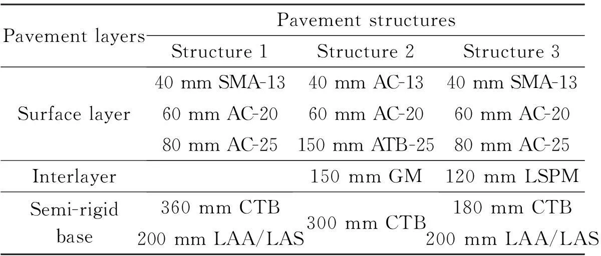
Tab.1 Typical pavement structures
Notes: SMA—stone matrix asphalt; AC—asphalt concrete; GM—graded materials or graded stones.
When defining boundary conditions, the bottom of the model was set to be completely constrained, and both sides were symmetrically constrained in the horizontal direction. The tire pressure was distributed in rectangular instead of circle. Each rectangular was 0.213 m×0.167 m in size to make sure that the loading contact patch was equal to the circular one. According to the static equivalent principle, the standard axle loading was converted to uniformly distributed pressureP(0.117 MPa) based on plane models in elasticity.
The layer-divided model without remeshing[17]was developed to simulate the development of reflective cracking in each layer. This model was based on the following assumptions: 1) Reflective cracking developed from bottom to top; 2) Only the fatigue caused by symmetric loads was considered; and 3) The fatigue life of the whole structure was the sum of the fatigue life of each layer.
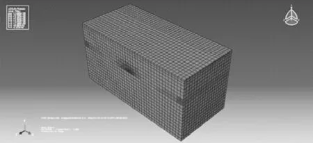
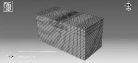
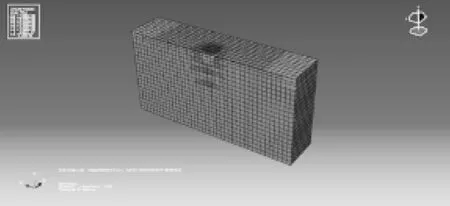
The procedures of building a ABAQUS model for Structure 1 are given as follows: First, the model for completed sub-base using LAS was built and the fatigue life was calculated as shown in Fig.1(a); the fatigue life of the CTB layer was calculated using LAS layer with transverse crack; while the fatigue life of AC-25 was calculated using LAS and CTB layer with transverse crack; the sub-surface layer AC-20 was calculated by the model of LAS, CTB and AC-25 with transverse crack; and the fatigue life of the surface layer SMA-13 was calculated by the model of LAS, CTB, AC-20 and AC-25 with transverse crack, as shown in Fig.1(b). The ABAQUS models for Structure 2 and Structure 3 were built using the same procedures.
(a)
(c)Fig.1 Procedures of building ABAQUS model for Structure 1. (a) Calculation of the fatigue life of LAS; (b) Calculation of the fatigue life of SMA-13
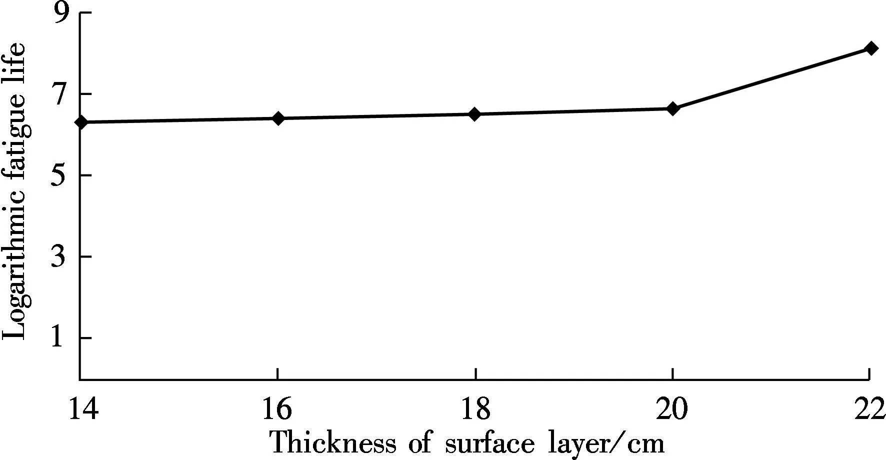
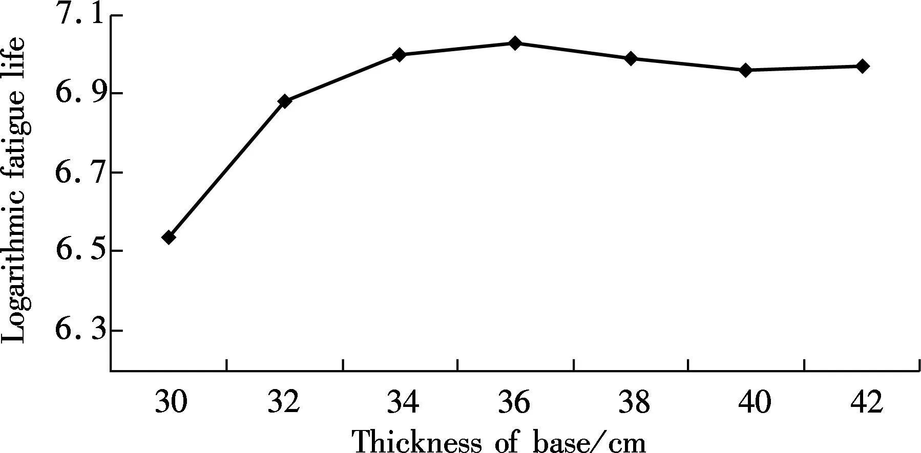
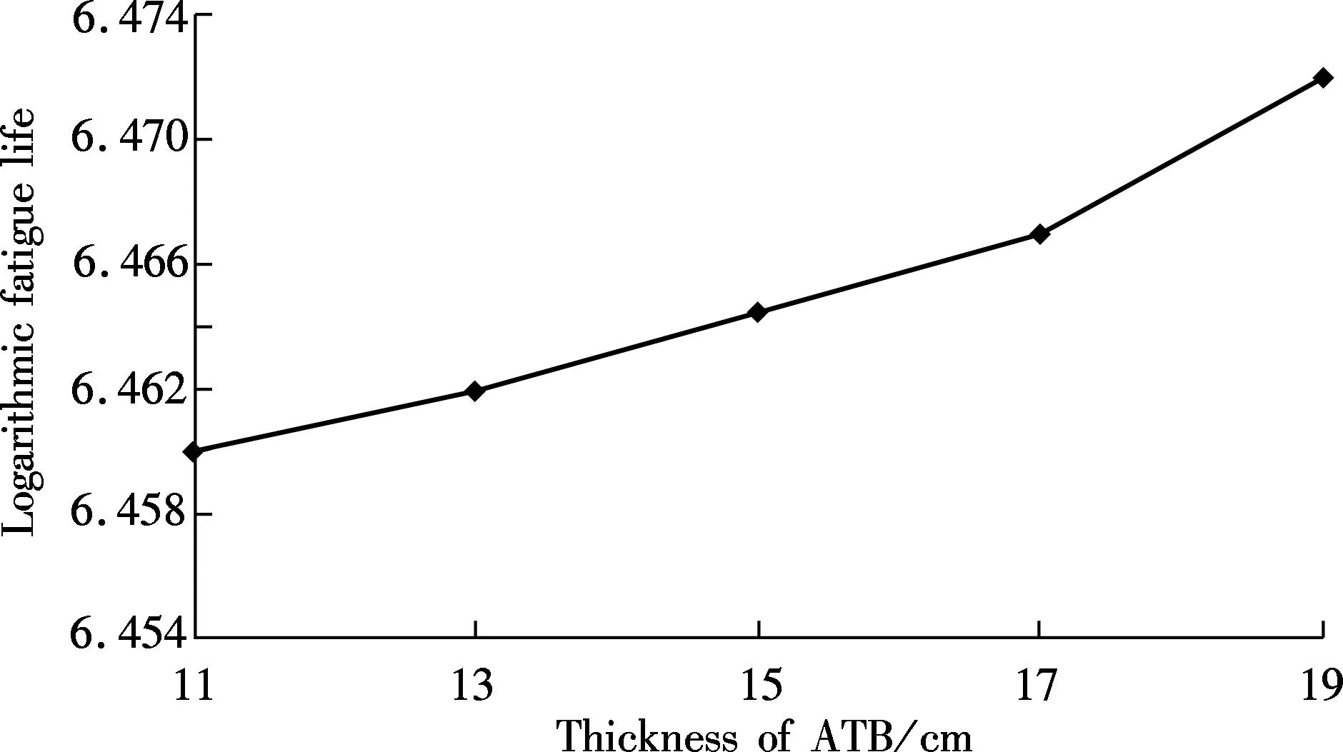
Then the results of ABAQUS were transferred into FE-SAFE for fatigue simulations. The SMA-13, AC-20, AC-25, CTB and LAS were put into the analysis group in FE-SAFE. Note that the GM in Structure 2 was removed from the analysis group because it had no contributions in the fatigue lives of pavement structures. In order to simulate the transition of stress at the center of the surface of the pavement, the loading pressure was transferred based on the following equation:
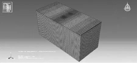
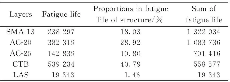
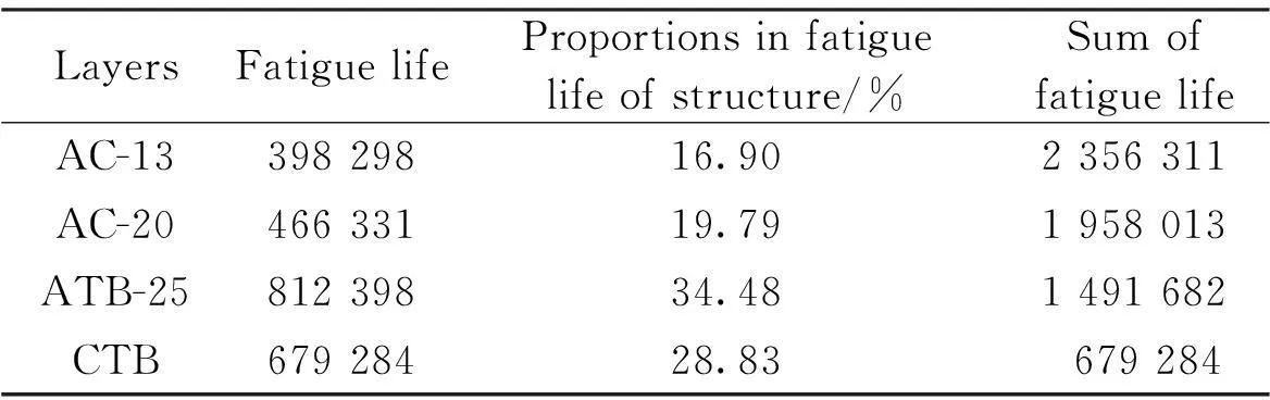
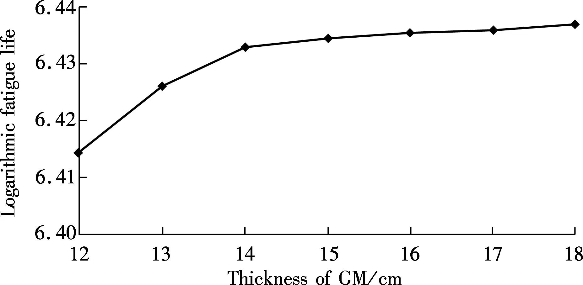
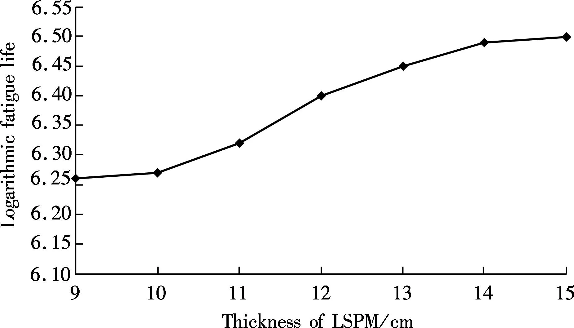
P(t)=sin(10πt)0 (1) where the amplitude is 1; the phase angle is -π/2; and the frequency is 10 Hz. After defining the properties of materials and the loading pressure in FE-SAFE, the calculations were operated in FE-SAFE to simulate the fatigue performance of pavement structures. Then the fatigue results in FE-SAFE were inputted into ABAQUS to obtain the isotherm graphs (see Fig.2(a)). In order to calculate the fatigue life of each layer, the ABAQUS models were separated along the centerline, as shown in Fig.2(b). Mark points were set in the center of each layer. Assume that the fatigue life of one particular mark point wasPk, then the elastic stress of this mark point can be calculated by (2) whereSPEandPFEare set by FE-SAFE according to the mechanical properties of materials in each layer. Then the fatigue life of each layer was calculated by repeating cycles under pressure defined previously according to the Miner theory. Finally, the logarithmic fatigue life of each layer from bottom to top was collected by calculating these mark points. This method was proved to be valid and had good correlations with indoor fatigue test results[18]. (a) (c)Fig.2 Isotherm graphs from ABAQUS. (a) Before the separation of the model; (b) After the separation of the model 2Comparisons of Fatigue Lives among Three Pavement Structures The results of fatigue life from the FE-SAFE model are shown in Tab.2, Tab.3 and Tab.4. Tab.2 Fatigue life of each layer in Structure 1 Tab.3 Fatigue life of each layer in Structure 2 Tab.4 Fatigue life of each layer in Structure 3 From Tabs.2 to 4, it can be seen that in the semi-rigid pavement structures, the proportions in fatigue life of each structure can be considered as the loading times of the reflective cracking in this layer. Considering the fact that the surface asphalt layer has better anti-cracking performance than other layers, if the surface asphalt layer has a large proportion in the fatigue life, the whole semi-rigid pavement structure can have better anti-cracking performance. The surface asphalt layer has the least proportion in the fatigue life in Structure 1 (57.75%) compared with Structure 3 (69.8%) and Structure 2 (71.77%), which means that the use of the outstanding anti-cracking performance of the surface asphalt layer is not fully developed in Structure 1. Tab.3 shows that the existence of the GM layer changes the proportions of the fatigue life of Structure 2 dramatically. The proportion of the fatigue life of ATB is 34.48% in Structure 2. It is confirmed that the ATB layer combined with the GM layer is beneficial in resisting reflective cracking in Structure 2. Tab.4 shows that even though the proportion of the LSPM layer in Structure 3 is only 0.4%, it leads to the increase in the proportions of the fatigue life of the surface asphalt layer (SMA-13, AC-20 and AC-25) (69.39%) compared with that of Structure 2 (36.69%). This means that the utilization of the LSPM layer can make good use of anti-cracking performance of the surface asphalt layer in Structure 3. From Tabs.2 to 4, it can also be seen that Structure 1 has the largest thickness (74 cm) with the shortest fatigue life (1 322 034), while Structure 3 has the smallest thickness (68 cm) with the longest fatigue life (2 958 627). It can be concluded that the aggregated base (Structure 2) and the LSPM base (Structure 3) are more effective in resisting reflective cracking than the conventional semi-rigid base (Structure 1). Different combinations of layers such as the aggregated base and the LSPM have positive effects on prolonging the fatigue life if the thickness of these layers are determined carefully. 3Effects of Layer Thickness on Fatigue Life of Three Pavement Structures Since the thickness of stress absorbing layers (SAL) is crucial in designing pavement structures to resist reflective cracking[13], it is necessary to investigate the effects of layer thickness on fatigue lives of three pavement structures. Wang[19]built a ABAQUS model and suggested that when the crushed stone base has a thickness in the range of 15 to 25 cm, the pavement structure has an outstanding anti-cracking performance. Zhang et al.[20]conducted simulations and field tests on anti-cracking performance of interface self absorbing composite (ISAC) and found that the ISAC can dissipate reflective cracking efficiently in a pavement structure. In this section, the thickness of each layer in the ABAQUS model was changed while performing calculations of the fatigue life of each layer in three pavement structures. The fatigue lives with respect to the thickness of each layer were given to determine the appropriate thickness when designing pavement structures. The effects of thickness of the surface layer and base on the fatigue life of Structure 1 are shown in Fig.3 and Fig.4, respectively. Fig.3 Correlation between thickness of surface layer and fatigue life Fig.4 Correlation between thickness of base and fatigue life Fig.4 shows that the fatigue life of Structure 1 increases as the thickness of semi-rigid base increases. However, if the thickness reaches 36 to 38 cm, the fatigue life decreases slightly as the thickness keeps increasing. This means that the increase in the thickness of the semi-rigid base cannot guarantee the increase of fatigue life in Structure 1. When the semi-rigid base is thin, the main stress in the base is tensile stress. However, the compressive stress starts to appear if the thickness goes beyond a threshold (36 cm in this case), and the stabilized materials in the semi-rigid base become unstable, begin to squeeze each other and change the mechanical property of the whole base. This process definitely sabotages the anti-cracking performance of the semi-rigid base. Meanwhile, the fatigue life increases steadily as the surface asphalt layer becomes thicker (see Fig.3). According to previous studies[21], the reflective cracking can be well mitigated by increasing the thickness of the surface asphalt layer. The surface asphalt layer has good anti-cracking performance. The effects of thickness of ATB and the GM layer on the fatigue life of Structure 2 are shown in Fig.5 and Fig.6, respectively. Fig.5 Correlation between thickness of ATB and fatigue life Fig.6 Correlation between thickness of GM and fatigue life Fig.5 and Fig.6 show clearly that the fatigue life increases when the thickness of the ATB layer increases. They also show that the fatigue life of Structure 2 increases dramatically if the thickness of the GM layer is less than 15 cm. The increase of fatigue life slows down as the thickness reaches 15 to 18 cm. The GM layer is the crucial part in Structure 2. It serves as the stress absorbing layer in this structure. Although it has no contributions in calculations of fatigue, it has an indirect impact on resisting reflective cracking from rapid propagation. However, the increase in the thickness of the GM layer can increase the fatigue life of Structure 2, which can lead to large fatigue strain in the ATB layer due to the relatively small modulus of the GM layer. This is the reason why the fatigue life of Structure 2 stops increasing when the thickness range of the GM is 15 to 18 cm. Hence, the recommended thickness for the GM layer is from 15 to 18 cm. The effect of thickness of the LSPM layer on fatigue life of Structure 3 is shown in Fig.7. Fig.7 Correlation between thickness of LSPM and fatigue life It can be seen from Fig.7 that the fatigue life of Structure 3 increases when the thick LSPM layer is utilized. This is similar to the trends of the GM in Structure 2. However, when the thickness of the LSPM reaches 15 cm, the increase of the fatigue life of Structure 3 slows down. The LSPM layer is the stress absorbing layer in Structure 3. The relatively low modulus leads to the increase of fatigue lives in other layers which come into contact with the LSPM layer. Even though the contribution of the LSPM layer itself in the fatigue life of Structure 3 is insignificant (0.4%), it results in the dramatic increase in proportions of fatigue lives of the surface asphalt layer (69.39%) and sub-base (LAS) (7.41%) in Structure 3 compared with that in Structure 1 (57.75% and 1.46%, respectively). This phenomenon can be explained in two aspects: as for the whole pavement structure, the compress stress from top to bottom and tensile stress from bottom to top can be disseminated when passing through the LSPM layer, as the GM layer does. As for the stress concentration, the reflective cracking needs more time and path to propagate through the LSPM layer due to the inconsistence at the edge of cracking. This can indirectly prolong the fatigue life of Structure 3. Unfortunately, determining the appropriate thickness range of the LSPM still remains unsettled. Although increasing the thickness of the LSPM layer is beneficial for resisting reflective cracking, it leads to the degeneration in anti-rutting performance of pavement structures. It is suggested from Fig.7 that the thickness of the LSPM in Structure 3 should be no more than 15 cm. 4Conclusions 1) The finite element models using ABAQUS and the fatigue models using FE-SAFE for three semi-rigid pavement structures are established in this paper. The impacts of the thickness of layers on the fatigue lives of three pavement structures are compared by calculating the fatigue lives by FE-SAFE. 2) The comparisons of the fatigue lives of three semi-rigid pavement structures suggest that the aggregated base and the LSPM base are more beneficial than the conventional semi-rigid base in resisting reflective cracking if they are properly deployed. The thickness of these layers need to be carefully determined. 3) The numerical simulation results show that the appropriate thickness range of the aggregated layer in the aggregated base is 15 to 18 cm, while the thickness of the LSPM layer in the LSPM base should be no more than 15 cm. References [1]Kim Y R, Baek C, Underwood B S, et al. Application of viscoelastic continuum damage model based finite element analysis to predict the fatigue performance of asphalt pavements [J].KSCEJournalofCivilEngineering, 2008, 12(2): 109-120. [2]Arshadi A, Bahia H. Coupling of viscoelastic continuum damage mechanics and finite element modeling to predict asphalt mastic fatigue behavior [C/D]//TRB94thAnnualMeetingCompendiumofPapers. Washington, DC, USA, 2015: 15-3321-1-15-3321-15. [3]Baek J, Al-Qadi I L. Finite element modeling of reflective cracking under moving vehicular loading: investigation of the mechanism of reflective cracking in hot-mix asphalt overlays reinforced with interlayer systems[C]//ProceedingsofASCE’s2008AirportandHighwayPavementsConference. Washington, DC, USA, 2008: 74-85. [4]Huang X M, Wang S J.Analysistheoryandpracticeofmodernasphaltpavementstructure[M]. Beijing: Science Press, 2013. (in Chinese) [5]Chen Z D, Wu J M, Zhang X R, et al. Investigation of the typical structure of trunk road asphalt pavement [J].JournalofHighwayandTransportationResearchandDevelopment, 2001, 18(2): 9-12. (in Chinese) [6]Jiang Y H, Huang X M, Liao G Y. Fracture mechanics analysis of pavement structure with a sandwich layer of unbound graded aggregate [J].JournalofHefeiUniversityofTechnology, 2009, 32(4): 511-514. (in Chinese) [7]Wang Y, Ni F J, Li Z X. Test and estimate control on temperature shrinkage performance of cement-treated macadam [J].JournalofSoutheastUniversity:NaturalScienceEdition, 2008, 38(2):260-264. (in Chinese) [8]Wu P, Houben L J M, Scarpas A, et al. Stiffness modulus and fatigue properties of cement stabilized sand with use of a synthetic modified-zeolite additive [C/D]//TRB94thAnnualMeetingCompendiumofPapers. Washington DC, USA, 2015:15-2880-1-15-2880-12. [9]Wang L, Feng D C. Methods for improving using performance of graded broken stone base [J].ChinaJournalofHighwayandTransport, 2006, 19(4): 40-45. (in Chinese) [10]Wang H, Li M Y. Evaluation of flexible pavement performance due to variations in aggregate base layer properties [C/D]//TRB94thAnnualMeetingCompendiumofPapers. Washington, DC, USA, 2015: 15-4877-1-15-4877-22. [11]Guo H B. Research on anti-cracking mechanism of open-graded large stone asphalt mixes of asphalt pavement [D].Xi’an: School of Highway of Chang’an University, 2013. (in Chinese) [12]Loria L, Hajj Y E, Sebaaly P E. Assessment of reflective cracking models for asphalt pavements [C]//ProceedingsofRoadPavementandMaterialCharacterization,Modeling,andMaintenance. Changsha, China, 2011:72-79. [13]Li Z Z, Chen S F, Cheng Y, et al. Fatigue test of composite pavement on stress absorbing layers for reflective cracking [C]//ThirdInternationalConferenceonTransportationEngineering(ICTE). Chengdu, China, 2011:1390-1395. [14]Wei D X. Distress mode and structure optimization of asphalt pavement with semi-rigid base [D]. Xi’an: School of Highway of Chang’an University, 2010. (in Chinese) [15]Wu J T. The rational position and thickness of semi-rigid base in asphalt pavement [D]. Xi’an: School of Highway of Chang’an University, 2009. (in Chinese) [16]Li H B. Study of asphalt pavement structure based on adaptability of semi-rigid base [D]. Xi’an: School of Highway of Chang’an University, 2010. (in Chinese) [17]Moes N, Dolbow J, Belytschko T. A finite element method for crack growth without remeshing [J].InternationalJournalforNumericalMethodsinEngineering, 1999, 46(1):131-150. [18]Liu W C. Numerical simulation of fatigue cracks in typical asphalt pavement [D]. Nanjing: School of Transportation of Southeast University, 2014. (in Chinese) [19]Wang H C. Research on surface and reflective crack propagation and fatigue life of graded crushed stone based asphalt pavement [C]//Proceedingsof11thInternationalConferenceofChineseTransportationProfessionals(ICCTP). Nanjing, China, 2011:3103-3114. [20]Zhang F, Zhang Y H, Qian H T, et al. Analysis and test study on reflective cracking prevention based on interface self-absorbing composite intermediate layer in semi-rigid asphalt pavement [C]//Proceedingsofthe11thInternationalConferenceofChineseTransportationProfessionals(ICCTP). Nanjing, China, 2011:3359-3367. [21]Abou-Jaoude G, Ghauch Z. Numerical investigation of design strategies to achieve perpetual pavements [C/D]//TRB91stAnnualMeetingCompendiumofPapers. Washington, DC, USA, 2012:12-1979-1-12-1979-16. doi:10.3969/j.issn.1003-7985.2015.04.019
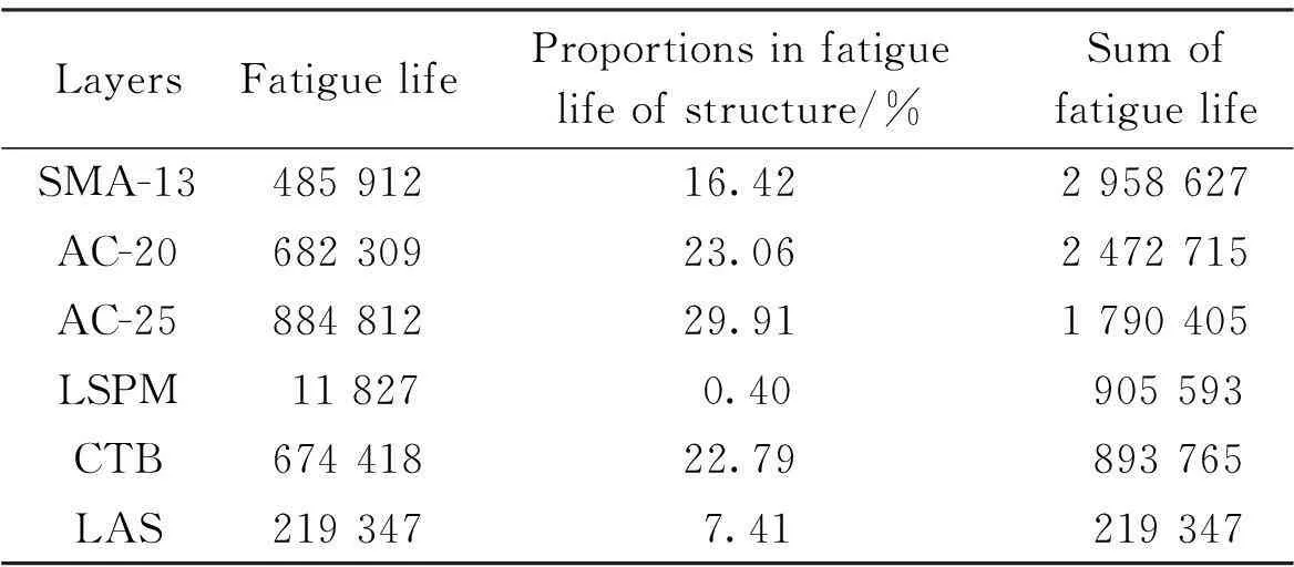
3.1 Effects of thickness of layers on fatigue life of Structure 1
3.2 Effects of thickness of layers on fatigue life of Structure 2
3.3 Effects of thickness of LSPM on fatigue life of Structure 3
杂志排行

Journal of Southeast University(English Edition)的其它文章
- Mitigation of inter-cell interference in visible light communication
- Modified particle swarm optimization-based antenna tiltangle adjusting scheme for LTE coverage optimization
- Distribution algorithm of entangled particles for wireless quantum communication mesh networks
- Kernel principal component analysis networkfor image classification
- CFD simulation of ammonia-based CO2 absorption in a spray column
- Simulation and performance analysis of organic Rankine cycle combined heat and power system