Systematic Synthesis of Grounded Gyrator Using Single CCCCTA*
2015-02-28,,
,,
(1.School of Information and Engineering,Shaanxi Institute of International Trade and Commerce,Xi’an 712046,China;2.School of Physics and Electronic Engineering,Xianyang Normal University,Xianyang Shaanxi 712000,China)
Since the theory of the NAM(Nodal Admittance Matrix)expansion was presented,it has found wide ap⁃plications in generation of a series of novel cir⁃cuits[1-14].Theoretically,the NAM expansion technique can be generalized to any active device.Although the literature[12-14]reported the pathological model for cur⁃rent conveyor transconductance amplifier(CCTA),it presented only one model of CCTA and did not provide the pathological model for the CCCCTA.Moreover,the NAM expansion method cannot be used to synthesize floating gyrators employing CCCCTAs.
Very recently,pathological model of the CCCCTA has been reported[15],but its applications include only floating gyrators.The paper aims at using NAM ex⁃pansion to realize grounded gyrators employing CCCCTAs.First,on the ground of the class-Ⅱ A and B of the gyrator NAM in the Literature[5]and using NAM expansion,eight alternative NAM equations are obtained,resulting in eight alternative realizations of gyrators.Next,based on the eight circuit models and 16 pathological models of the CCCCTA,four alternative gyrators employing CCCCTAs are received by means of NAM expansion method.EWB simulations are given to illustrate the principles involved.
1 Basic concept of the CCCCTA
It is known that the circuit representations for the various CCCCTAs are shown in Fig.1.The terminal re⁃lations of the CCCCTA can be characterized by the fol⁃lowing set of equations[15]:


Fig.1 Circuit symbols for the various CCCCTAs
Here,the“+”notation indicates CCCCTA+and the“-”notation ICCCCTA-.For a CCCCTA imple⁃mented with bipolar technology,the parasitic resistance at the x input terminal,Rx,could be expressed to be[15]

The transconductance gain of the CCCCTA,gm,can be expressed[15]

Here,IB1andIB2are the DC bias currents of the CCCCTA andVTis the thermal voltage.
2 Equivalent Realizations of Two-Type Grounded Gyrators
There are two types of grounded gyrators that can be achieved by using CCCCTAs.The NAM for class A gyrators is given by[5]

Here,ZLis the grounded impedance at port 2.
2.1 Class A gyrators
Since two types of the gyrators contain four nodes,the first step in the NAM expansion is to add two blank rows and columns to Eq.(4).Then,following succes⁃sive NAM expansion steps produces[5]:

Eq.(7)shows thatG1is the grounded conductance connected node 3,andG2is the grounded conductance connectednode4.TheaboveequationisrealizedinFig.2(a)[5].
The second alternative NAM expansion can also be obtained,as shown in Eq.(8).

The equivalent realization is given in Fig.2(b)[5].
Similarly,the third alternative NAM expansion can be obtained,as shown in Eq.(9).The equivalent realization is given in Fig.2(c)[5].

Similarly,the fourth alternative NAM expansion can be obtained,as shown in Eq.(10).The correspond⁃ing realization is given in Fig.2(d)[5].


Fig.2 Nullor-mirror models for class A gyrators
It is seen that class A gyrators have four nullormirror representations with two different pairs of patho⁃logical elemnts and two grounded conductances.
2.2 Class B gyrators
Similarly,Starting from the gyrator port admit⁃tance matrix in Eq.(5),following successive NAM ex⁃pansion steps,and applying all possible combinations of the added nullor-mirror elements,will yield the ex⁃panded equations shown in Eq.(11).

Four nullor-mirror equivalent circuits for the gyrators described by Eq.(11)are given in Fig.3.
It must be noted that Fig.2 is the same as Fig.2(a)~Fig.2(d)in the Literature[5],and Fig.3 is the same as Fig.2(e)~Fig.2(h)in the Literature[5]if the posi⁃tion of the nodes 1,2 is interchanged.
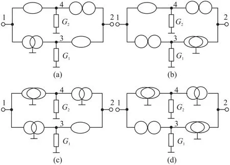
Fig.3 Nullor-mirror models for class B gyrators
3 RealizationofFourCCCCTABased Grounded Gyrators
From Fig.2 and 16 pathological models of the CCCCTAs[15],four alternative realizations of class A gy⁃rators can be equivalent as Fig.4,whereG1andG2on the left-hand side denote the parasitic resistance at thexinput terminal of the CCCCTA,G1andG2on the righthand side denote the transconductance gain of the OTA in the CCCCTA.Similarly,from Fig.3 and 16 pathological models of the CCCCTAs,four alternative realizations of class B gyrators can be equivalent as Fig.5,where the significance ofG1andG2is as before.
It is noteworthy that the circuit of Fig.4 is the same as Fig.5 if the position of the nodes 1,2 is inter⁃changed andG1andG2is interchanged.This means eight alternative realizations yield only four equivalent circuits using one CCCCTA.It can also be seen that the OTA in the circuits of Fig.4 and Fig.5 employs ei⁃ther a single input single positive output OTA or a sin⁃gle input single negative output OTA,resulting in the simplest realizations of the circuits.

Fig.4 CCCCTA-based realizations for class A gyrators

Fig.5 CCCCTA-based realizations for class B gyrators
4 Simulation Results
The workability of the derived gyrators has been verified by realizing a band pass filter.Fig.6 shows the schematics for the realization of the second-order bandpass filter that employs the simulated grounded induc⁃tor based on Fig.4(b),whose value is given by

The transfer function realized by this configura⁃tion is given by

Here,Viis input voltage andVois output voltage.The pole frequency and the quality factor are as follows:

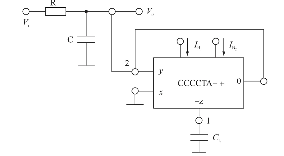
Fig.6Second-order band-pass filter using Fig.(5b)
Here,IB1=IB2=IB,C=CL=1 nF.IfR=1 kΩ,andIB=52 μA,104μA,and 208μA,from Eq.(14),the design value forfois 0.318 MHz,0.637 MHz,and 1.274 MHz;from Eq.(15),the design value forQis 2,4,and 8.
In order to test the performances of the derived circuits,the CCCCTA of Fig.6 was constructed from Fig.4 in the literature[15].Fig.6 was,therefore,created.Finally,the circuit in Fig.6 was simulated with ±1.5 V power supplies.WhenR=1 kΩ,C=CL=1 nF,andIB=104 μA,the simulation result is shown in Fig.7.

Fig.7 Band-pass responses for R=1 kΩ,C=CL=1 nF,and IB=104 μA
Using the pointer in MULTISIM yields the actual values forfois 0.618 MHz,the corresponding deviation forfois-2.98%,the actual value forQis 3.88,the cor⁃responding deviation forQis-3.00%.
To illustrate the controllability offoandQby ad⁃justingIB,letR=1 kΩ,C=CL=1 nF,andIB=52 μA,104 μA,and 208 μA.The simulation result is shown in Fig.8.Using the pointer in MULTISIM yields the actu⁃al values forfois 312 kHz,618 kHz and 1.212 MHz,re⁃spectively;the actual value forQis 1.99,3.88,and 7.51.It is seen that MULTISIM simulation results have verified the theoretical results.

Fig.8 Band-pass responses for R=1 kΩ,C=CL=1 nF,and different IB
5 Conclusions
This is the first paper in which the use of the NAM expansion method in the synthesis of CCCCTA based grounded gyrators is considered.The main fea⁃ture of the paper is making use of systematic design method to obtain novel circuit.Also,the grounded gyra⁃tors synthesized possess four forms and enjoy two ad⁃vantages,namely electronic tunable parameter and on⁃ly use of single CCCCTA component.The results of cir⁃cuit simulations are in agreement with theory.
Acknowledgement
This work is supported by the Natural Science Foundation of Shaanxi Province(Grant No.2012JM8017).The author would also like to thank the anonymous reviewers for their suggestions.
[1]Haigh D G,Clarkr T J W,Radmore P M Symbolic Framework for Linear Active Circuits Based on Port Equivalence Using Limit Variables[J].IEEE Transactions on Circuits and Systems I,2006,53(9):2011-2024.
[2]李永安.CCCDTA的零-镜实现及其对正交振荡器综合的应用[J].电子器件,2013,36(3):320-324.
[3]Li Y A.NAM Expansion Method for Systematic Synthesis of OTA-based Floating Gyrators[J].AEU-International Journal of Elec⁃tronics and Communication,2013,67(4):289-294.
[4]Saad R A,Soliman A M.Use of Mirror Elements in the Active De⁃vice Synthesis by Admittance Matrix Expansion[J].IEEE Trans⁃actions on Circuits and Systems I,2008,55(9):2726-2735.
[5]Saad R A,Soliman A M.Generation,Modeling,and Analysis of CCII-based Gyrators Using the Generalized Symbolic Framework for Linear Active Circuits[J].International Journal of Circuit The⁃ory and Applications,2008,36(3):289-309.
[6]Saad R A,Soliman A M.On the Systematic Synthesis of CCⅡ-Based Floating Simulators[J].International Journal of Circuit Theory and Applications,2010,38(9):935-967.
[7]Li Y A.On the Systematic Synthesis of OTA-Based Wien Oscilla⁃tors[J].AEU-International Journal of Electronics and Communi⁃cation,2013,67(9):754-760.
[8]李志军,鲁光德,王春华.基于MOCCCⅡ的双模式二阶通用滤波器[J].电子器件,2007,30(5):1594-1596.
[9]Li Y A.Systematic Synthesis of OTA-Based T-T Filters Using NAME Method[J].Journal of Circuits,Systems,and Computers,2013,22(3):1-17.http://dx.doi.org/10.1142/S0218126613500023.
[10]赵怡,王卫东.一种基于CMOS CCDVCCⅡ的可编程多功能滤波器及可编程测量放大器[J].电子器件,2011,34(1):53-56.
[11]赵怡,王卫东.一种新型的宽线性范围差分电压输入电流传输器及其应用[J].电子器件,2011,34(2):179-183.
[12]Sanchez-Lopez C.Pathological Equivalents of Fully-Differential Active Devices for Symbolic Nodal Analysis[J].IEEE Transac⁃tions on Circuits and Systems I,2013,60(3):603-615.
[13]Sanchez-Lopez C,Cante-Michcol B,Morales-Lopez F E,Carrasco-Aguilar M A.Pathological Equivalents of CMs and VMs with Multi-Outputs[J].Analog Integrated Circuits and Signal Process⁃ing,2013,75(1):75-83.
[14]Siripruchyanun M,Jaikla W.Current Controlled Current Conveyor Transconductance Amplifier(CCCCTA):a Building Block for Analog Signal Processing[J].Electrical Engineering,2008,90(6):443-453.
[15]Li Y A.NAM Expansion Method for Systematic Synthesis of Float⁃ing Gyrators Using CCCCTAs[J].Analog Integrated Circuits and Signal Processing,2015;82(3):733-743.

李永安(1961-),男,陕西三原人,1983年毕业于西北大学物理系。现为咸阳师范学院物理与电子工程学院教授,研究领域为电流模电路的分析与综合设计,lya6189@tom.com。
