Effecrive Esrimarion for UAV Propeller Performance
2015-02-09LiuLi刘莉ShiShangtao施商涛ZhangXiaohui张晓辉GuoChangwei郭昌伟
Liu Li(刘莉),Shi Shangtao(施商涛),Zhang Xiaohui(张晓辉),Guo Changwei(郭昌伟)
School of Aerospace Engineering,Beijing Institute of Technology,Beijing 100081,P.R.China
(Received 12 March 2013;revised 6 February 2015;accepted 8 March 2015)
Effecrive Esrimarion for UAV Propeller Performance
Liu Li(刘莉)*,Shi Shangtao(施商涛),Zhang Xiaohui(张晓辉),Guo Changwei(郭昌伟)
School of Aerospace Engineering,Beijing Institute of Technology,Beijing 100081,P.R.China
(Received 12 March 2013;revised 6 February 2015;accepted 8 March 2015)
Absrracr:A new effective propeller performance estimation method is employed to calculate the propeller performance in the preliminary design of unmanned aerial vehicles(UAVs).The propeller three-dimensional aerodynamic characteristics leading to the blade tip vortices are considered to improve the blade element theory.The rule of the airfoil lift coefficient is summarized to enhance the calculation speed and the universality of this method.Then,wind tunnel test data of the propellers are used to verify the correctness of the approach.The error is less than 9%,which is accurate enough in the preliminary design of UAVs.Sensitivity analysis is carried out with the variable empirical parameters,and the values of which only have slight influence on the calculated results.Compared with the strip theory,the proposed method avoids a very high number of iterations and complicated integral.Furthermore,only a few measurable data are needed to get a relatively accurate result.The calculation examples demonstrate excellent effectiveness in obtaining the propeller performance to improve the design of UAVs.
propellers;strip theory;preliminary design of UAVs;blade tip effect
0 Inrroducrion
During the conceptual design and preliminary performance analysis of propeller aircraft,the propulsive efficiency,the power and the corresponding thrust must be determined at various speeds[1].Three main theories were used to analyze the propeller performance,but every of them had some limitations[2].Phillips pointed out that most designers objected to use the classical propeller momentum theory because of its failure to account for the rotation of the fluid within the slipstream[3].Lotstedt summarized the limitations in the blade element theory that the flow around each section of the blade which was regarded as a twisted wing was locally two-dimensional and the section was only approximate[4].All the wings had finite aspect ratio which led to wingtip vortex,as well as the finite-diameter propeller.It affected the flowfields around the propeller and decreased the actual angle of attack of every blade element,especially that near the blade tip.The strip theory which considers induced angles,and the blade element momentum theory need complicated iterations and integral in order to get accurate results.
While wind tunnel tests and optimized designs can obtain more accurate results[5],they are costly in terms of both money and time,and these methods are better to be used in detailed designs of unmanned aerial vehicles(UAVs).The designer would like a fast and relatively accurate prediction for the propeller performance in the preliminary design,assuming that a computer aided method or an optimized propeller design will be used later in the process.Solies used a numerical method to estimate the propeller efficiencies,where the efficiencyηis converged quickly after 7—8 steps of iterations[1].Although Solies'method is fast in obtainingη,the results are not accurate enough,only showing proper trends.
In this paper,a simple and relatively accurate method is proposed to calculate the propeller performance in the preliminary design of UAVs.Theinduced angle is regarded as a function of flight velocity and slipstream velocity,avoiding the complicated iterations.It is usually difficult to clear the relationship between induced angle and other propeller parameters for designers,dealing with large iterations.To get a rapid calculation,spanwise average method is used to calculate the aerodynamic forces instead of integral.Dividing the propeller blade into many parts may have a more accurate aerodynamic forces result,but it is not the best appropriate method because of spanwise average method with faster calculation and a good accuracy(See Part 2,example and discussion),which is more important in the preliminary design of UAVs.During this period,designers have more interested in propeller parameters and propeller performance variation trends which will greatly affect the UAV design.Thanks to the high-performance computation environment and the advanced numerical methods,numerical investigating for the physical features or motions becomes faster and more accurate.However,computational fluid dynamics(CFD)takes very long time to capture complicated flow features of wake vortices from the blade tips or to deal with the blade three-dimensional(3D)aerodynamics[6]. Leishman and Glauert used a tip loss factor method to calculate the blade tip loss[7,8].In his work,a tip loss essentially corresponded to a reduction in the propeller disc area by a factor B2,which was the function of thrust coefficient CT.However,CTwas one of the propeller performance results we need to calculate.In present,3D wing aerodynamic theory is selected to improve accuracy regarding the blade tip vortices.It just affects the blade element attack of angle,and the value can be easily obtained.The rule of the airfoil lift coefficient is summarized to enhance the calculation speed and the universality.
1 Esrablishmenr of Enhanced Model
The enhanced model is based on the blade element momentum theory which is a combination of the momentum theory and the strip theory.A detailed strip theory was described by Gur[9],and only a brief summary is given here to emphasize several important features.
1.1 Blade geomerry
For the element d r of a single blade at the radial station,r=iR,where R is the propeller radius and i the ratio of r and R.The propeller blade element nomenclature is shown in Fig.1.
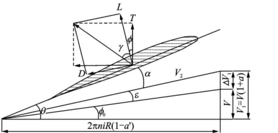
Fig.1 Propeller blade element nomenclature
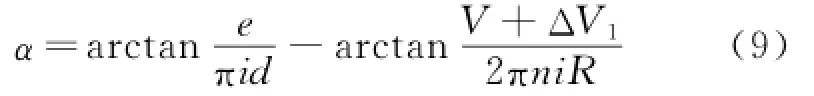
For a fixed-pitch propeller,the blade element pitch angleθis defined as
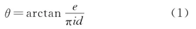
where e is the propeller pitch and d the propeller diameter.In most cases,a typical value of i=0.7 will be used[10].
Detailed momentum theory is proposed by Glauert[8].Consider a fluid element of mass d m,far upstream moving toward the propeller disc with velocity V,i.e.the UAV flight speed.It arrives at the disc with an increased velocity V1= V+ΔV1=V(1+a),where a is the disc interference factor andΔV1the induced velocity.The mass element d m moves downstream into the far wake,increasing speed to the value V2=V(1+ b),where b is the axial slipstream factor and V2the slipstream velocity.The axial momentum theory determines b to be approximately 2a.By similar arguments,the circumferential velocity is given by

From Adkins'work,we can see that a'is much smaller than a[11].And the disc interference factor a'is usually ignored in the blade element momentum theory[2].The better are some relationships and definitions according to Fig.1.
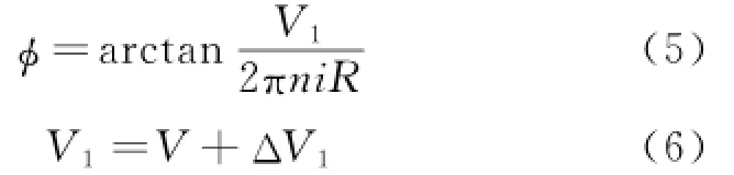
whereαis the angle of attack and n the revolution number.The induced velocity and slipstream velocity are difficult to be calculated because they vary along the radius of the blade and they are also the function of thrust[12,13].The thrust hardly affects slipstream velocity when slipstream is far away from the propeller disc,and the slipstream factor b has usually a typical value of 2/3[14]. Therefore,ΔV1=V/3 will be used for the study. The resultant velocity at propeller disc can be written as
1.2 Rule of lifr coefficienr
From the airfoil data[15],we can give the conclusion that the infinite aspect ratio lift coefficient Cl∞generated by most blade elements at low-tomoderate angles of attack varies linearly with the absolute angle of attackαabs

whereα0is the airfoil zero-lift angle of attack.For a symmetric airfoilα0=0,whereas for an asymmetric airfoil with positive camber,α0is a negative value,usually on the order of-2°—-4°. Andαabsis the sum of the absolute value of two angles.
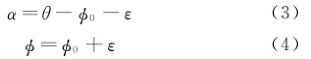
Then according to Eqs.(1—6),αcan be expressed as
The influence of different aspect ratios on the lift coefficient must be considered for an accurate estimation result of propeller performance,i.e. the blade tip vortices cannot be ignored in the process of modeling because it will decrease the actual angle of attack of every blade element.
The lift coefficient for different aspect ratios of a wing is shown in Fig.2.The lift slope K0can be easily calculated when the aspect ratio is infinite

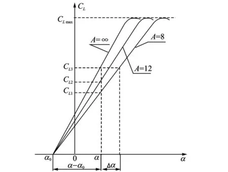
Fig.2 Lift coefficient angle of attack for different aspect ratios of wing
For most airfoils,a typical value of K0= 0.1/(°)will be used(See Fig.2).The finite aspect ratio lift slope KAis given by the following expression
whereΔαis the induced angle of attack,which is caused by the fluid curling around the blade tip and defined as[16]
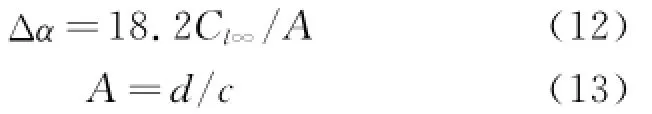
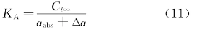
where A is the aspect ratio and c the average chord of the blades.The finite aspect ratio lift coefficient is written as

Substituting Eqs.(8—12)into Eq.(14)results in
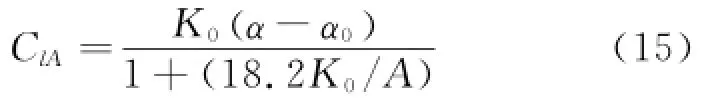
Eq.(15)gives the three-dimensional finite aspect ratio lift coefficient,showing that different aspect ratios make different lift coefficients at the same angle of attack.The lift coefficient deceases because of the aspect ratio,and the lift slope is also changed.
The blade element drag coefficients include the form drag coefficient CD0and the induced drag coefficient CDi,which can be expressed as

where kiis the correction coefficient of the propeller flat shape.It falls between the following values

A value of ki=1.3 will be used when the blade tip is rectangular,while ki=1.05 when the blade tipis elliptic.For a light propeller,CD0is usually on the order of 0.02—0.03.
The drag-lift angleγis defined as

The lift of blade element is defined as follows
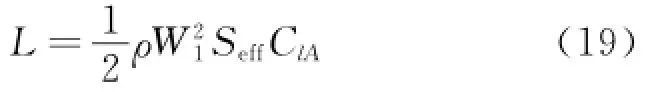
whereρis the fluid density and Seffthe effective area of the propeller

where N is the blade number of the propeller and kethe effective area coefficient.In most cases,the value of ke=0.7—0.8 will be used.
Finally,the thrust,torque,power,efficiency,advance ratio,thrust coefficient,torque coefficient,power coefficient are determined respectively by the following equations

2 Example and Discussion
To calculate the propeller performance,some parameters should be known:(1)the propeller diameter d;(2)the propeller pitch e;(3)the propeller average chord c;(4)the blade number N;(5)the flight speed V;(6)the revolution number n.d and e are usually given by the propeller producer,c and N can be easily measured. The mission profile of UAVs determines the flight speed V.If these parameters are already known,the thrust and efficiency are mainly determined by n or the advance ratio J.
To obtain the propeller performance,one can proceed as follows without iterations and integral:(1)computeθ,Eq.(1);(2)compute V1,Eq.(6);(3)computeφ,Eq.(5);(4)withθandφ calculated,get a value ofαfrom Eq.(3);(5)compute W1,Eq.(7);(6)compute A,Eq.(13);(7)compute ClA,Eq.(15);(8)compute CD,Eq.(16);(9)computeγ,Eq.(18);(10)compute Seff,Eq.(20);(11)compute L,Eq.(19);(12)calculate J,CT,CQ,CP,T,Q,P andηusing Eqs.(21—28).
An example of a propeller(APC12×12E)with d=0.304 8 m,e=0.304 8 m,c=0.019 1 m,V=15.82 m/s,N=2,n=6 431 r/min,i=0.7,α0=-2°,K0=0.1/(°),CD0=0.025,ki=1.1,and ke=0.7 is used,and the predicted data are shown in Table 1,as well as the measured data tested by wind tunnel experiments[17].
As can be seen in Table 1,the error of the torque and the power is less than 9%.For thrust,the most important parameter during the flight of UAV,the error is less than 5%.The error of efficiency equals 3.0%,which is reasonably accurate for predicting the propeller performance in the preliminary design.

Table 1 Comparison of predicred dara and measured dara(APC12×12E)
Another propeller performance is estimated at different flight speeds when n=4 000 r/min. The predicted data CTand CPare compared by measured data[5]shown in Fig.3.In most cases,the predicted data of power coefficient match well with the measured data,as well as the thrust coefficient.However,the error of CTincreases when J decreases because of the following three reasons:(1)The equationΔV1=V/3 cannot be used when V is very small,i.e.J is very small. For example,the induced velocityΔV1is obviously larger than zero when V=0;(2)The slope of the lift coefficient curve gradually reduces near thecritical angle of attackαstall,and the linear relationship between the angle of attack and the lift coefficient is not accurate whenα=αstall,and Cldoes not vary linearly with the absolute angle of attackαabs;(3)The blade's cross sections experience stall becauseαwill be larger thanαstallwhen V is very small(See Fig.1).In the mission profile of UAVs,only two period of time will experience small velocity:the beginning of taking off and the end of landing.These two states are not very important and can even be ignored because of its short time.
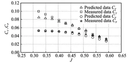
Fig.3 Data comparison of APC11×8 propeller performance
3 Sensiriviry Analysis
The enhanced method includes four variable empirical parameters:the airfoil zero-lift angle of attackα0,-2°—-4°;the form drag coefficient CD0,0.02—0.03;the correction coefficient of the propeller flat shape ki,1.05—1.3;and the effective area coefficient ke,0.7—0.8.In the example of the previous section,nominal representative values of all these parameters are used.Yet some differences exist between various flight states and propellers.The purpose of sensitivity analysis is to study the influence of these differences on the calculation of the propeller performance.The study will include variations of one of the parameters,whereas all the other parameters are equal to their nominal values.

Table 2 Sensiriviry of CD0(0.02—0.03)
The changes of CD0and kionly result in a very small relative variation of CT,CPandη,less than 4%as shown in Tables 2,3.The values of α0and keshould carefully be chosen because the variations exceed 10%along the entire range of CTand CP,as shown in Tables 4,5.The efficiency is almost the same no matter howα0and kehave changed.
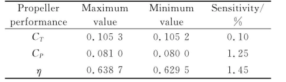
Table 3 Sensiriviry of ki(1.05—1.3)
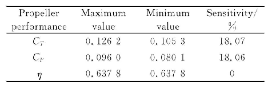
Table 4 Sensiriviry ofα0(-2°—-4°)

Table 5 Sensiriviry of ke(0.7—0.8)
4 Conclusions
Analysis results show that the method works well to predict the propeller performance except when the velocity is very small.In the strip theory,a very high number of iterations and integral should be operated.Furthermore,the distribution along the blade of the following parameters:the pitch angleβ(r),the chord c(r),and the blade airfoils should be known in order to obtain an accurate result.However,these parameters are difficult to measure.The strip theory is costly in terms of time,hence it can be used in detailed design of UAVs.The parameters d,e,c,N,n,V can be easily known,so the propeller performance can be easily calculated without iterations and integral by the method proposed in this paper.The sensitivity analysis indicates that the differences of empirical parameters only have slight influence onthe calculated results.Because of its relatively simplicity and reasonably accuracy,the method is useful to calculate the propeller performance during the conceptual design and preliminary performance analysis of UAVs.
Acknowledgemenr
This work was supported by the National Aerospace Science Foundation of China(2011ZA72003).
[1] Solies U P.Numerical method for estimation of propeller efficiencies[J].Journal of Aircraft,1993,31(4):996-998.
[2] Liu Peiqing.Aerodynamic theory and application of propellers[M].Beijing:Beijing University of Aeronautics and Astronautics Press,2006.(in Chinese)
[3] Phillips W F.Propeller momentum theory with slipstream rotation[J].Journal of Aircraft,2001,39(1):184-187.
[4] Lotstedt P.Accuracy of a propeller model in inviscid flow[J].Journal of Aircraft,1995,32(6):1312-1321.
[5] Brandt B J,Selig S M.Propeller performance data at low Reynolds numbers[R].AIAA Paper 2011-1255,2011.
[6] Hyung-I1 K,Seulgi Y,Taehee K,et al.Aerodynamic design of EAV propeller using a multi-level optimization method[R].AIAA Paper 2013-2523,2013.
[7] Leishman G J.Principles of helicopter aerodynamics[M].New York:Cambridge University Press,2006.
[8] Glauert H.Airplane propellers[M].New York:Dover,1963.
[9] Gur O,Rosen A.Comparison between blade element models of propellers[J].The Aeronautical Journal,2008,112(1138):689-704.
[10]Sabzehparvar M.In-flight thrust measurements of propeller[J].Journal of Aircraft,2005,42(6):1543-1547.
[11]Adkins C N.Design of optimum propellers[J].Journal of Aircraft,1994,10(5):676-682.
[12]Sun Chuanwei,Gao Zheng.Enhanced unsteady and nonlinear rotor wake model for real-time flight simulation[J].Transactions of Nanjing University of Aeronautics and Astronautics,2003,20(1):12-15.
[13]Kasim B.Estimating propeller slipstream drag on airplane performance[J].Journal of Aircraft,2011,48(6):2172-2174.
[14]Zhu Baoliu.UAV aerodynamics[M].Beijing:Aviation Industry Press,2006.
[15]Gregory A W,Bryan D M,Benjamin A B.Summary of low-speed airfoil data[M].Urbana:University of Illinois,2002.
[16]Anderson J D.Fundamentals of aerodynamics[M]. 3nd ed.New York:Mc Graw-Hill,2001.
[17]Merchant M P,Miller L S.Propeller performance measurement for low Reynolds number UAV applications[R].AIAA Paper 2006-1127,2006.
(Executive Editor:Xu Chengting)
V211.44Documenr code:AArricle ID:1005-1120(2015)05-0502-06
*Corresponding aurhor:Liu Li,Professor,E-mail:liuli@bit.edu.cn.
How ro cire rhis arricle:Liu Li,Shi Shangtao,Zhang Xiaohui,et al.Effective estimation for UAV propeller performance[J].Trans.Nanjing U.Aero.Astro.,2015,32(5):502-507.
http://dx.doi.org/10.16356/j.1005-1120.2015.05.502
猜你喜欢
杂志排行

Transactions of Nanjing University of Aeronautics and Astronautics的其它文章
- Developmenr Srraregy of Engine Bird Ingesrion Cerrificarion Technology
- Vision Enhancemenr Technology of Drivers Based on Image Fusion
- Flurrer Analysis of Aircrafr Wing Using Equivalenr-Plare Models wirh Orrhogonal Polynomials
- Comparison of Passive Conrrol Merhods on Caviry Aeroacousric Using Delayed Derached Eddy Simularion
- Accuracy Analysis on Bundle Adjusrmenr of Remore Sensing Images Based on Dual Quarernion
- Search Space Pruning Based on Image Tools for Preliminary Inrerplanerary Trajecrory Design